Free 186 More Best Homemade Tools eBook:  
Get 2,000+ tool plans, full site access, and more.

User Tag List

Page 1 of 2 1 2 LastLast
Results 1 to 10 of 13

Thread: 12”X37” Metal Lathe Digital Tachometer

  1. #1
    Supporting Member Paul Jones's Avatar
    Join Date
    May 2014
    Location
    Del Mar, California
    Posts
    1,231
    Thanks
    5,810
    Thanked 1,441 Times in 655 Posts

    Paul Jones's Tools

    12”X37” Metal Lathe Digital Tachometer

    I was inspired by the “Lathe & Mill Tachometer” posted by Catfish (see his 4-2-2014 post by Randy Richard and his YouTube video), and decided to install the same type of product on my old 12”X37” geared-head metal lathe. I previously used the same type of display and sensor for my 7” swing mini-lathe (see Homemade Mini Lathe Digital Tachometer).

    Randy advised searching for “Hall Effect Tachometer” parts on eBay. I found many offered in the range of $13 to $20 and I purchased one with a blue LED display. The eBay purchase included the LED display with bezel and its attached circuit board that snaps into a rectangular cutout, the cabled Hall Effect sensor NPN with nuts and lock washers, and a small rare-earth magnet. The simple wiring diagrams are posted with the products photos on eBay. I also purchased for $3 a small 110VAC to 9VDC power supply circuit board. I used eBay “Buy It Now” and the parts arrived within a few days.

    I mounted the digital display into an aluminum case (1.5”x2”x4”) after cutting a rectangular opening the old fashion way with a nibbler (could have milled it but I wanted to show another way to do this). I machined, from ½” aluminum rod, a support column threaded 3/8-24 and ½” long on each end and drilled a ¼” dia. thru hole for the wires. 3/8-24 jam nuts are used to attach the support column to the aluminum case and to the lathe electrical box. On the side of the case is a SPST miniature toggle switch for powering on/off the tachometer.

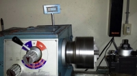
    I created a simple aluminum bracket for mounting the Hall Effect sensor. The bracket positions the sensor less than a 2 mm gap from sensor end to the spinning magnet mounted near the rear of the spindle (sensor specs require a 1 to 10 mm gap). The rare earth magnet is epoxied to the spindle after verifying the north-pole end is pointing up (the sensor only works this way). An existing threaded rod bracket for attaching the lathe rear cover was used to attach the bracket to avoid drilling into the headstock. The sensor wires are held safely in place with tie-wrap mounts and guided around the back of the lathe and into the lathe electrical box.

    In the lathe electrical box I installed the 110VAC to 9VDC power supply circuit board (secured in place with tie wraps) and used solid core wires with screw lug connectors to connect to the line power. The 9VDC wires and the sensor wires both go through the hollow support column and connect to the circuit board. I choose a circuit board with surface mount electronics that draw less than 40mA current and the small 500mA 9VDC power supply circuit is more than sufficient.
    Attached Thumbnails Attached Thumbnails 12”X37” Metal Lathe Digital Tachometer-geared-head-lathe-tachometer-addition.jpg   12”X37” Metal Lathe Digital Tachometer-hall-effect-sensor-lathe-tachometer.jpg   12”X37” Metal Lathe Digital Tachometer-lathe-tachometer-sensor-bracket.jpg   12”X37” Metal Lathe Digital Tachometer-wiring-tachometer-case.jpg   12”X37” Metal Lathe Digital Tachometer-lathe-tachometer-case-before-wiring.jpg  

    12”X37” Metal Lathe Digital Tachometer-lathe-tachometer-case-support-column.jpg   12”X37” Metal Lathe Digital Tachometer-using-nibbler-cut-display-opening.jpg   12”X37” Metal Lathe Digital Tachometer-110vac-9vdc-power-supply-wired-line-.jpg  

    186 More Best Homemade Tools eBook
    Last edited by Paul Jones; Mar 21, 2016 at 09:41 AM. Reason: Added more details about the power supply

  2. The Following 4 Users Say Thank You to Paul Jones For This Useful Post:

    Altair (Mar 15, 2015), jjr2001 (Sep 1, 2016), kbalch (Mar 9, 2015), Rangi (May 13, 2018)

  3. #2
    kbalch's Avatar
    Join Date
    Jun 2012
    Location
    Clermont, FL
    Posts
    5,034
    Thanks
    2,275
    Thanked 531 Times in 383 Posts
    Thanks Paul! I've added your Metal Lathe Digital Tachometer to our Lathe Accessories and Digital Readouts categories, as well as to your builder page: Paul Jones' Homemade Tools. Your receipt:


    2000 Tool Plans

  4. #3
    Content Editor
    Supporting Member
    DIYer's Avatar
    Join Date
    Aug 2013
    Posts
    3,056
    Thanks
    772
    Thanked 1,852 Times in 1,653 Posts
    Thanks for the detailed post, Paul Jones! It's certainly going to help someone in the future.

  5. #4
    Content Editor
    Supporting Member
    Altair's Avatar
    Join Date
    Aug 2013
    Posts
    11,902
    Thanks
    1,361
    Thanked 29,709 Times in 9,873 Posts
    That's a nice upgrade. Excellent work, Paul. Thanks for sharing.

  6. The Following User Says Thank You to Altair For This Useful Post:

    Paul Jones (Mar 15, 2015)

  7. #5
    Jon
    Jon is online now Jon has agreed the Seller's Terms of Service
    Administrator
    Supporting Member
    Jon's Avatar
    Join Date
    Jan 2012
    Location
    Colorado, USA
    Posts
    25,540
    Thanks
    7,950
    Thanked 38,793 Times in 11,326 Posts

  8. #6
    Supporting Member Catfish's Avatar
    Join Date
    Oct 2013
    Location
    Mariposa, California
    Posts
    271
    Thanks
    55
    Thanked 418 Times in 157 Posts

    Catfish's Tools
    Very nice build Paul, I love the compact display setup. Randy

  9. #7
    Supporting Member Paul Jones's Avatar
    Join Date
    May 2014
    Location
    Del Mar, California
    Posts
    1,231
    Thanks
    5,810
    Thanked 1,441 Times in 655 Posts

    Paul Jones's Tools
    Thanks Randy. You provided the original idea and directions. I added the tachometer because I have been experimenting with different motor pulley diameters and the new speeds differ from what are shown on the RPM labels to the gear speed selections. Next, I plan to add a tooling shelf above the lathe headstock gear box and wanted the display to be seen above the shelf. Paul

  10. #8
    Supporting Member Paul Jones's Avatar
    Join Date
    May 2014
    Location
    Del Mar, California
    Posts
    1,231
    Thanks
    5,810
    Thanked 1,441 Times in 655 Posts

    Paul Jones's Tools
    Thanks for the tip for seeing Hackaday.com. Very fresh and interesting website with lots of ideas.

  11. #9
    Supporting Member Catfish's Avatar
    Join Date
    Oct 2013
    Location
    Mariposa, California
    Posts
    271
    Thanks
    55
    Thanked 418 Times in 157 Posts

    Catfish's Tools
    Paul, did you take into consideration about the lathe speed data plate, was it developed with a 50hz motor in mind? I know my lathe was. Randy

  12. #10
    Supporting Member Paul Jones's Avatar
    Join Date
    May 2014
    Location
    Del Mar, California
    Posts
    1,231
    Thanks
    5,810
    Thanked 1,441 Times in 655 Posts

    Paul Jones's Tools

    Lathe Motor Plate

    Randy,
    Good point and explains the speed differences. The original owner replaced the original motor with a 60HZ electric motor. See the photo of the motor plate. I suspect the original motor was 50HZ with a different max rotor RPM and this explains the speed discrepancies despite using the same pulley configurations.
    Attached Thumbnails Attached Thumbnails 12”X37” Metal Lathe Digital Tachometer-leeson-1.5hp-motor-plate.jpg  

Thread Information

Users Browsing this Thread

There are currently 1 users browsing this thread. (0 members and 1 guests)

Tags for this Thread

Bookmarks

Posting Permissions

  • You may not post new threads
  • You may not post replies
  • You may not post attachments
  • You may not edit your posts
  •