Free 186 More Best Homemade Tools eBook:  
Get 2,000+ tool plans, full site access, and more.

User Tag List

Results 1 to 7 of 7

Thread: Chuck Mandrel for a small 5” 4-jaw Chuck

  1. #1
    Supporting Member Paul Jones's Avatar
    Join Date
    May 2014
    Location
    Del Mar, California
    Posts
    1,231
    Thanks
    5,810
    Thanked 1,441 Times in 655 Posts

    Paul Jones's Tools

    Chuck Mandrel for a small 5” 4-jaw Chuck

    Previously I published a similar project about a mandrel for a Yamakawa 80mm 3-jaw chuck with a set of toolmakers mini jaws (see http://www.homemadetools.net/forum/c...0262#post72147 ). The new mandrel in this posting is very similar in size but is designed to hold a 5” 4-jaw Bison chuck in a larger 3-jaw chuck. The small 4-jaw chuck had been used on my 7" mini lathe but this lathe is now used almost exclusively for small collet work using ER32 collets. Now while using the 12" swing geared head lathe, there are times when a smaller 4-jaw chuck with a mandrel would be much easier to install into the D1-4 mounted 6” 3-jaw chuck than swapping out the 6” chuck for the heavier 8” 4-jaw chuck.


    Chuck Mandrel for a small 5” 4-jaw Chuck-mandrel-5-inch-4-jaw-chuck-mounted-3-jaw-chuck.jpg

    Chuck Mandrel for a small 5” 4-jaw Chuck-mandrel-5-inch-4-jaw-chuck.jpg

    Chuck Mandrel for a small 5” 4-jaw Chuck-mandrel-attached-5-inch-4-jaw-chuck.jpg


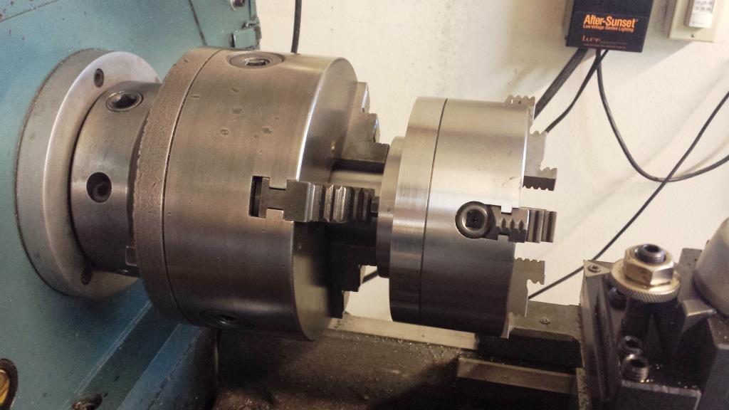
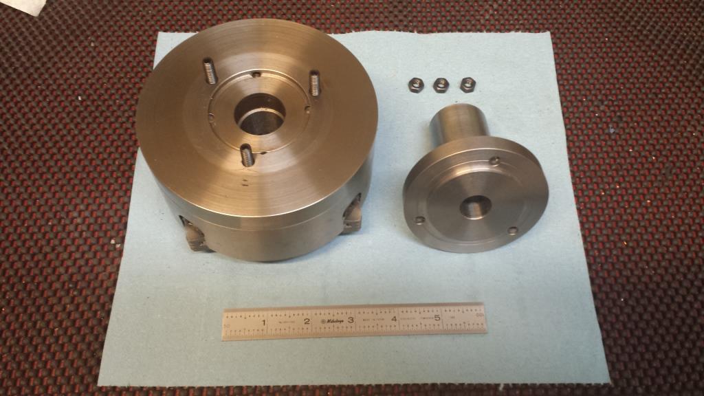
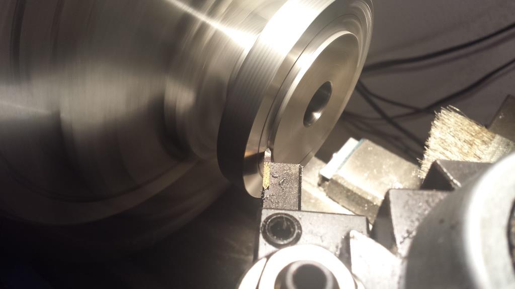
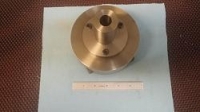
    The 5” Bison 4-jaw chuck now has a mandrel machined from 1045 alloy carbon steel 3.25" round bar stock. The mandrel has an overall length of 3.3” and the shaft dimensions are 1.5” dia. x 2.5” long. The chuck is attached with three M6x1 studs and nuts on the larger end that is 3.20” dia.x 0.375” thick. In addition the larger end has a 0.110” deep step that inserts snugly into a recess in the back of the 5” 4-jaw chuck. The three holes for the studs were located with a inscribed circle marked while still mounted for machining in the lathe. The center-to-center cord was calculated and used to locate the three holes centers with a pair of dividers. The bolt holes are 0.257” dia. (Letter F drill). A 0.700” thru hole runs down the center of the mandrel.

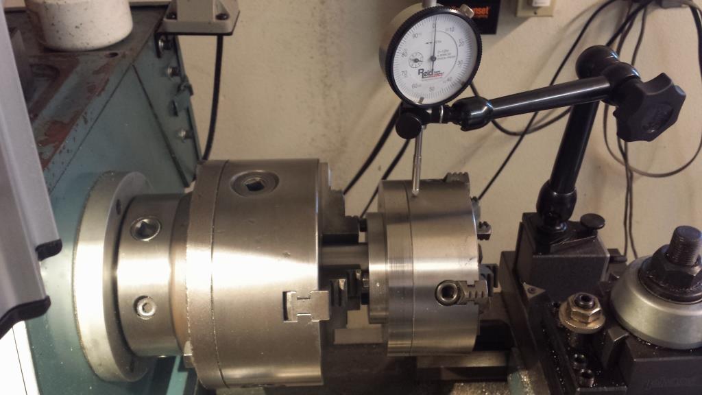
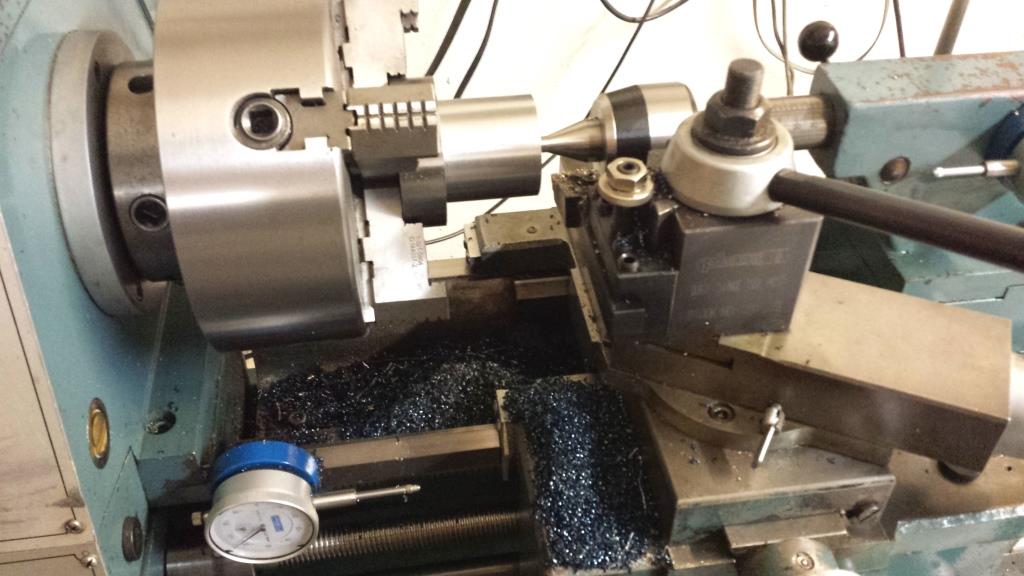
    Below are photos taken while machining the mandrel

    Chuck Mandrel for a small 5” 4-jaw Chuck-4-jaw-chuck-mandrel-combined-tir-0.001-inch.jpg

    Chuck Mandrel for a small 5” 4-jaw Chuck-machining-1045-crs-mandrel-smaller-diameter.jpg

    Chuck Mandrel for a small 5” 4-jaw Chuck-machining-corner-relief-nikcole-mini-systems-threading-insert.jpg


    Thank you for looking,

    Paul Jones

    186 More Best Homemade Tools eBook
    Last edited by Paul Jones; Dec 5, 2016 at 09:38 AM.

  2. The Following 3 Users Say Thank You to Paul Jones For This Useful Post:

    C-Bag (Dec 5, 2016), jjr2001 (Dec 5, 2016), PJs (Dec 5, 2016)

  3. #2
    Supporting Member C-Bag's Avatar
    Join Date
    Aug 2015
    Location
    California, central coast
    Posts
    720
    Thanks
    689
    Thanked 876 Times in 471 Posts

    C-Bag's Tools
    Nice project and great documentation Paul. Just curious about doing bolt circles accurately. You mention about laying out the centerline, but how did you divide and drill the holes? Did you do it on the lathe or? I'm trying to figure out how to do bolt circles especially when there is no center point to go by, as in the brake rotors on my trike.

    Seems like some kind of dividing setup for the lathe head like Christophe or Olderdan would be the ticket with some kind of adapter for drilling.

    2000 Tool Plans

  4. The Following 3 Users Say Thank You to C-Bag For This Useful Post:

    jjr2001 (Dec 5, 2016), Paul Jones (Dec 5, 2016), PJs (Dec 5, 2016)

  5. #3
    Supporting Member mklotz's Avatar
    Join Date
    Aug 2015
    Location
    LA, CA, USA
    Posts
    3,437
    Thanks
    357
    Thanked 6,391 Times in 2,118 Posts

    mklotz's Tools
    Quote Originally Posted by C-Bag View Post
    I'm trying to figure out how to do bolt circles especially when there is no center point to go by, as in the brake rotors on my trike.
    If the center of the workpiece has a largish hole, find the center by sweeping the hole with a DTI. Then you can locate the bolt holes by coordinates. You can use the program BOLTCIRC from my page to calculate the coordinates relative to the center or calculate them yourself using the following equations...

    n = number of holes
    r = RADIUS (half the diameter) of the bolt circle
    a = 360 / n = angle between adjacent holes

    Calculate x,y coordinates, measured from the center of the work, as follows for k = 0,1,2, ... up to k = n-1

    x = r * cos (k * a)
    y = r * sin (k * a)
    Last edited by mklotz; Dec 5, 2016 at 10:14 AM.
    ---
    Regards, Marv

    Home Shop Freeware
    https://www.myvirtualnetwork.com/mklotz

  6. The Following 4 Users Say Thank You to mklotz For This Useful Post:

    C-Bag (Dec 5, 2016), jjr2001 (Dec 5, 2016), Paul Jones (Dec 5, 2016), PJs (Dec 5, 2016)

  7. #4
    PJs
    PJs is offline
    Supporting Member PJs's Avatar
    Join Date
    Sep 2014
    Location
    Northern CA
    Posts
    1,841
    Thanks
    8,337
    Thanked 1,118 Times in 718 Posts

    PJs's Tools
    Thank you Paul for another great write up and pics. The idea of these mandrel chuck in a chuck seems a good way to go, especially having to go to an 8" to get the 4 jaws...almost need a hoist for something like that. Think you and JR have started a trend. I particularly liked that you used the "Old School" divider technique to determine you hole centers on the BC. It was one of the first exercises I used to teach drafting students. If students get the geometry into their hands and minds then moving to CAD is a piece of cake. What can be done with a pencil, ruler and compass has always been near and dear to me. Thanks for sharing that here.

    I am curious how that 5" bison ran on the mini. Any reduction in power or other issues? I've been wanting a 4 jaw for ages but was considering the 4" LMS to match my 4" 3 jaw. Bison's are very nice chucks and used them on my Drill Machines but may be out of my price range.

    P.S. Not to undercut Marv's great posting or his Calculator C-Bag, but I use a program called ShopCalc by Richard Sanders up in Canada. It is a VB program that will run in Win7 and calculates all this stuff including X/Y bolt circles. I would also bet there is an app for your Apple Tablet. It might be worth your while though to give the divider technique a try.

    Thanks, ~PJ
    ‘‘Always do right. This will gratify some people and astonish the rest.’’
    Mark Twain

  8. The Following 3 Users Say Thank You to PJs For This Useful Post:

    C-Bag (Dec 5, 2016), jjr2001 (Dec 5, 2016), Paul Jones (Mar 20, 2018)

  9. #5
    Supporting Member Paul Jones's Avatar
    Join Date
    May 2014
    Location
    Del Mar, California
    Posts
    1,231
    Thanks
    5,810
    Thanked 1,441 Times in 655 Posts

    Paul Jones's Tools
    Thanks Marv for the formulas.

    C-Bag, I inscribed the bolt circle center line while the mandrel was still in the lathe chuck. I had just finished machining the boss on the end the mandrel and knew its exact diameter. Using the boss as a reference edge, I remove the backlash from the cross slide, and loosened the dog point set screws holding the lathe tool holder to allow pressing a sharp pointed lathe tool against the boss and re-tightened the set screws. This allowed me to know exact location of the lathe tool point and I then backed the cross slide out to one half the difference of the bolt circle diameter minus the boss diameter. Lightly plunging the lathe tool into the mandrel front surface scribes the bolt circle.

    I had previously measured the bolt circle on the back of the 5" 4-jaw chuck by installing two tight bolts, measuring the separating distance and then calculating the cord distance, and finally the bolt circle diameter. The 3 hole spacing on the mandrel was done with a spring divider set to the the cord distance which is bolt center-to-center distance. I use a Machinist Calc Pro model 4087 to calculate the bolt pattern dimensions. I use this calculator in my shop for many machining and layout calculations.

    The three holes were drilled in the mandrel with a dress press and not by x-y coordinates or indexer on a milling machine. I use a prick punch, followed by a center punch, and a sharp 1/8" diameter spot drill, 1/8" drill, and finally the Letter F drill. I can usually drill the holes right on or within 0.002", so I don't bother with a milling machine unless everything has to be exact.

    In the case of your brake rotors, I suggest making a disk with a boss that fits into the center hole and has a small spot drill dimple in the center. Use spring dividers to scribe the bolt circle, and then lay out the bolt holes center-to-center distances with the spring divider, and go around in both directions to double check your work. Prick punch and center punch the holes. Use the brush applied Dykem for a very dark contast and you can check your inscribed arc intersections from both directions for quality control before using the prick punch.

    Regards, Paul
    Last edited by Paul Jones; Dec 5, 2016 at 01:43 PM.

  10. The Following 3 Users Say Thank You to Paul Jones For This Useful Post:

    C-Bag (Dec 5, 2016), jjr2001 (Dec 5, 2016), PJs (Dec 5, 2016)

  11. #6
    Supporting Member Paul Jones's Avatar
    Join Date
    May 2014
    Location
    Del Mar, California
    Posts
    1,231
    Thanks
    5,810
    Thanked 1,441 Times in 655 Posts

    Paul Jones's Tools
    PJs,

    You have a good concern about running the 5" 3-jaw chuck on a mini lathe with a 7" swing. I know others had simialr concerns when I first published the article about mounting the chuck on the mini (see http://www.homemadetools.net/forum/a...4269#post18042 ). I could not see any reduction in power (monitoring the RPMs while machining is the main reason I installed tachometers on my lathes) but the extra mass really helps with the rotational momentum and I don't think the extra mass is harming the headstock bearings. This is no longer an issue now that the mini is run win an ER32 collet for most work and no need for the 5" chuck on the mini lathe.

    I bought the 5" Bison 4-jaw chuck in 1993 and it didn't seem too expensive at the time but Bison chucks today are pretty expensive. Last year I bought an 8" 4-jaw Fuerda/Gator D1-4 mounted chuck for the 12' swing geared head lathe and found the quality to be excellent. There is great story at Practical Machinist about how the Fuerda/Gator company was started and the quality control used to inspect their chucks (see A story about Bison & Fuerda (Gator) chucks ... ). This Black Friday, I ordered a 6" 6-jaw set tru Fuerda/Gator chuck at a considerable discount and looking forward to making it my main chuck on the 12" lathe.

    Paul
    Last edited by Paul Jones; Mar 20, 2018 at 09:52 PM.

  12. The Following 3 Users Say Thank You to Paul Jones For This Useful Post:

    C-Bag (Dec 5, 2016), jjr2001 (Dec 5, 2016), PJs (Dec 5, 2016)

  13. #7
    Content Editor
    Supporting Member
    DIYer's Avatar
    Join Date
    Aug 2013
    Posts
    3,056
    Thanks
    772
    Thanked 1,852 Times in 1,653 Posts


    Thanks Paul Jones! We've added your Chuck Mandrel to our Lathe Accessories category,
    as well as to your builder page: Paul Jones's Homemade Tools. Your receipt:


    186 More Best Homemade Tools eBook

Thread Information

Users Browsing this Thread

There are currently 1 users browsing this thread. (0 members and 1 guests)

Bookmarks

Posting Permissions

  • You may not post new threads
  • You may not post replies
  • You may not post attachments
  • You may not edit your posts
  •