Free 186 More Best Homemade Tools eBook:  
Get 2,000+ tool plans, full site access, and more.

User Tag List

Page 3 of 10 FirstFirst 1 2 3 4 5 6 7 8 9 10 LastLast
Results 21 to 30 of 91

Thread: CNC router build from Adept robotic cartesian slides.

  1. #21
    Supporting Member machiningfool's Avatar
    Join Date
    Jul 2015
    Location
    Seffner Florida
    Posts
    265
    Thanks
    0
    Thanked 271 Times in 146 Posts

    machiningfool's Tools
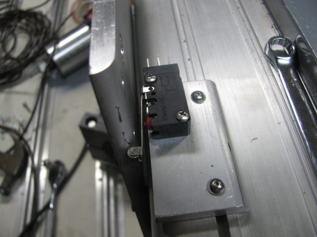
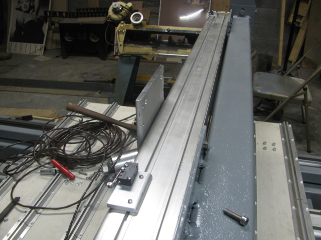
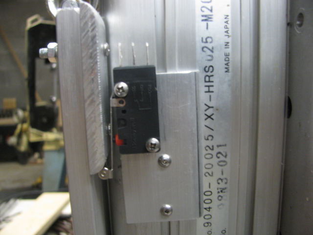
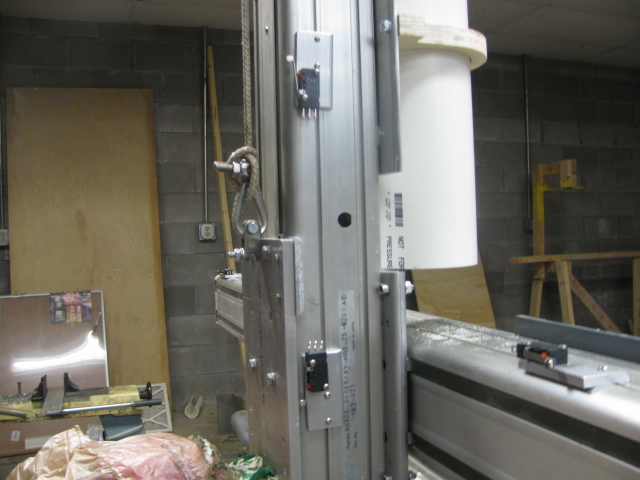
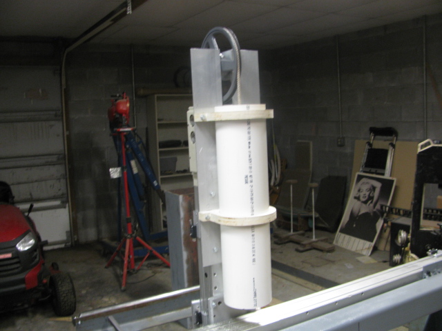
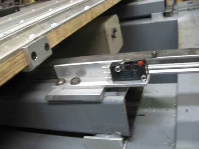
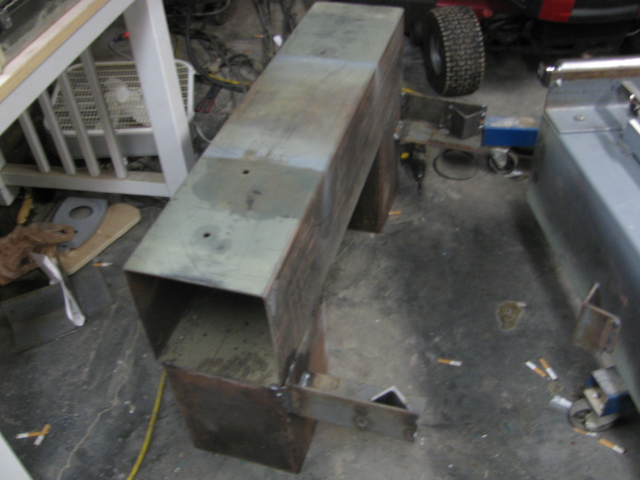
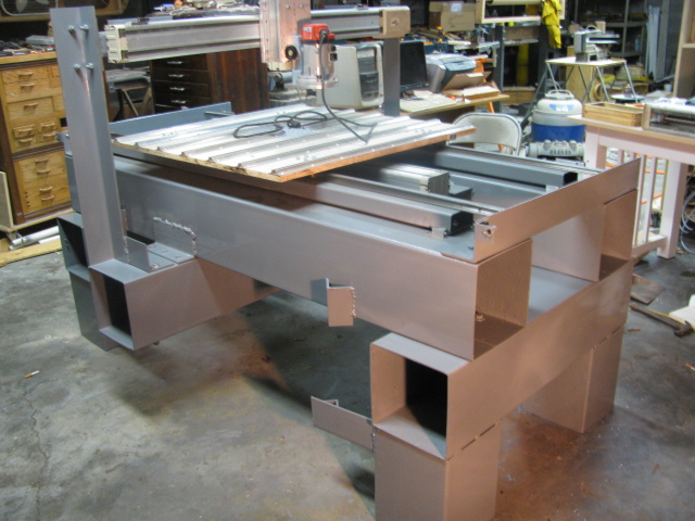
    The last few days, I have been installing limit switches and making the mounting for them. The Adept modules have little races to mount things, and I used them. It happens that a 4-40 nut just fits into the groove. I was looking through some old junk and ran across an old microscope base with nice V ways, and I thought that this would work well for a manual Z axis adjustment for the cutter. It will be easy to zero the Z axis by just turning a knob, I am going to mount it to see if it will work out, some pics. of the start of the micro switches and the axis addition. Bob.
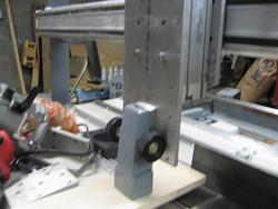
CNC router build from Adept robotic cartesian slides.-img_2296.jpgCNC router build from Adept robotic cartesian slides.-img_2298.jpgCNC router build from Adept robotic cartesian slides.-img_2299.jpg

    186 More Best Homemade Tools eBook

  2. The Following User Says Thank You to machiningfool For This Useful Post:

    PJs (Oct 4, 2015)

  3. #22
    Supporting Member machiningfool's Avatar
    Join Date
    Jul 2015
    Location
    Seffner Florida
    Posts
    265
    Thanks
    0
    Thanked 271 Times in 146 Posts

    machiningfool's Tools
    Thank you PJs, for the thank you. Today I finished the mechanism to adjust the Z axis manually, and it looks like it will work, unless, of course, the casting cracks. It is not made for this sort of thing, it is a microscope adjustment mechanism, but it might. If it doesn't, oh well, back to the drawing board. It seems quite strong, but the vibration could change that, I hope it doesn't. Here is a short video. I have my buttons in the mail from Prolabs, they look very professional, can't wait to hook them up. Bob.

    2000 Tool Plans

  4. The Following User Says Thank You to machiningfool For This Useful Post:

    PJs (Oct 7, 2015)

  5. #23
    Supporting Member machiningfool's Avatar
    Join Date
    Jul 2015
    Location
    Seffner Florida
    Posts
    265
    Thanks
    0
    Thanked 271 Times in 146 Posts

    machiningfool's Tools
    Here is the counter weight assembly finished, took 15 lbs. to counter. Also the Z axis micro limit switches. Bought the fabric for the covering of the ways, digging out my sewing machine. Any one know how to load the bobbin? CNC router build from Adept robotic cartesian slides.-img_2309.jpgCNC router build from Adept robotic cartesian slides.-img_2308.jpgCNC router build from Adept robotic cartesian slides.-img_2310.jpg

  6. The Following 2 Users Say Thank You to machiningfool For This Useful Post:

    Jon (Oct 7, 2015), PJs (Oct 7, 2015)

  7. #24
    Supporting Member machiningfool's Avatar
    Join Date
    Jul 2015
    Location
    Seffner Florida
    Posts
    265
    Thanks
    0
    Thanked 271 Times in 146 Posts

    machiningfool's Tools
    Today I mounted the X axis limit switches. I realized today that I made a mistake in estimating the travel of the x axis when figuring the length of the way cover. It turns out that I have to raise the machine 14 inches to accommodate the length of the cover, oh well, back to the drawing board. Bob.CNC router build from Adept robotic cartesian slides.-img_2311.jpg

  8. #25
    PJs
    PJs is offline
    Supporting Member PJs's Avatar
    Join Date
    Sep 2014
    Location
    Northern CA
    Posts
    1,841
    Thanks
    8,337
    Thanked 1,118 Times in 718 Posts

    PJs's Tools
    A pleasure! Thanks for the regular updates on a great project! Adding the microscope slide is excellent, very precise rack and pinions they have. Sure you will figure out a brake of some kind. ~PJ
    ‘‘Always do right. This will gratify some people and astonish the rest.’’
    Mark Twain

  9. #26
    Supporting Member machiningfool's Avatar
    Join Date
    Jul 2015
    Location
    Seffner Florida
    Posts
    265
    Thanks
    0
    Thanked 271 Times in 146 Posts

    machiningfool's Tools
    Thank you Jon and Pjs, I will just keep trudging along until I am done. I am involved in raising the machine 14 inches to allow for the way cover, oh well, it will be better higher anyway, then I will get back to the wiring of the machine. Bob.

  10. #27
    Supporting Member machiningfool's Avatar
    Join Date
    Jul 2015
    Location
    Seffner Florida
    Posts
    265
    Thanks
    0
    Thanked 271 Times in 146 Posts

    machiningfool's Tools
    Well, let me tell you what I have been doing. I attempted to cut and weld the leg extensions and then my welder failed. After 2 days of trouble shooting, I found the problem. It was a simple set screw that fell out of the hose between the gas solenoid and the hose leading to the torch. This is a MIG, by the way. I remember when and where it happened. I had just installed a new .030 in. tip and started to weld and it welded perfectly. Then I decided to pull on the dolly that houses the wire feeder to move it to a better position, and their is where it happened, but I didn't know it at the time.CNC router build from Adept robotic cartesian slides.-img_2315.jpg The fitting that allows the gas from the solenoid to go into the hose was displaced 1/4 inch and blocked the gas from going to the hose. I took everything apart, blowing on each section and finding that there was no blockage until I got to that fitting. I also repaired two gas leaks along the way. Thinking it was a bad solenoid, I was waiting until Monday to go buy one for 150.00. After thinking about the fact that it might not be the solenoid, I looked further and there it was. The fitting was missing a setscrew, and after looking more closely, I saw the groove where the gas should go and it was blocked, that is why there was no gas to the torch. Two O rings later, and a setscrew and I was back in business. So now I have one set of legs welded and while I was jacking up the router, the jack ram started spewing hydraulic fluid all over the place, so there I go down to Harbor freight to buy another ram. Tomorrow maybe I will have the legs installed to a new height. The welder welds so nice now, and hopefully the cherry picker will actually pick. Also the extensions that you see on the legs are for casters. Got my buttons from POLABS and a pendant, both are beautiful and will look nice on the cabinet. So, that is what I have been doing. Here is a picture of the raised legs. Bob.

  11. #28
    Supporting Member machiningfool's Avatar
    Join Date
    Jul 2015
    Location
    Seffner Florida
    Posts
    265
    Thanks
    0
    Thanked 271 Times in 146 Posts

    machiningfool's Tools
    OK, I can now continue with the build. The next thing is the way covers. I will have to pull out the sewing machine, hope I can figure out how to wind the bobbin. Here is the raised machine. Bob.CNC router build from Adept robotic cartesian slides.-img_2317.jpg

  12. The Following User Says Thank You to machiningfool For This Useful Post:

    PJs (Oct 13, 2015)

  13. #29
    Supporting Member Frank S's Avatar
    Join Date
    Aug 2015
    Location
    Peacock TX
    Posts
    11,210
    Thanks
    1,982
    Thanked 8,785 Times in 4,206 Posts

    Frank S's Tools
    looking good. But I can't help wondering if all of those large hollow sq tubes that make up the frame will become resonating chambers. I am pretty sure I can already hear a machine that will deafen everyone around.
    Foam filling may help if the time comes but for sure capped ends and oil soaked fine sand packed into all cavities will kill of many decibels plus effectively turn the frame into a dead solid block which will serve to cancel out much of the possible harmonic or possibly ultrasonic resonance if it occurs.
    Never try to tell me it can't be done
    When I have to paint I use KBS products

  14. The Following User Says Thank You to Frank S For This Useful Post:

    PJs (Oct 13, 2015)

  15. #30
    Supporting Member machiningfool's Avatar
    Join Date
    Jul 2015
    Location
    Seffner Florida
    Posts
    265
    Thanks
    0
    Thanked 271 Times in 146 Posts

    machiningfool's Tools
    I really won't know until I run the machine, but this is not a stepper system, this is a servo system, so no buzzing of the servos. If you are talking about the cutter, well we shall see. The vibrations will have to go through three layers of wood and then into the tubing. Resonance is a funny thing depending on the freqs. Don't know yet. If all else fails, I could make a pipe organ out of it. Thanks. Bob.
    Last edited by machiningfool; Oct 13, 2015 at 11:31 PM.

Thread Information

Users Browsing this Thread

There are currently 1 users browsing this thread. (0 members and 1 guests)

Bookmarks

Posting Permissions

  • You may not post new threads
  • You may not post replies
  • You may not post attachments
  • You may not edit your posts
  •