-
3 Attachment(s)
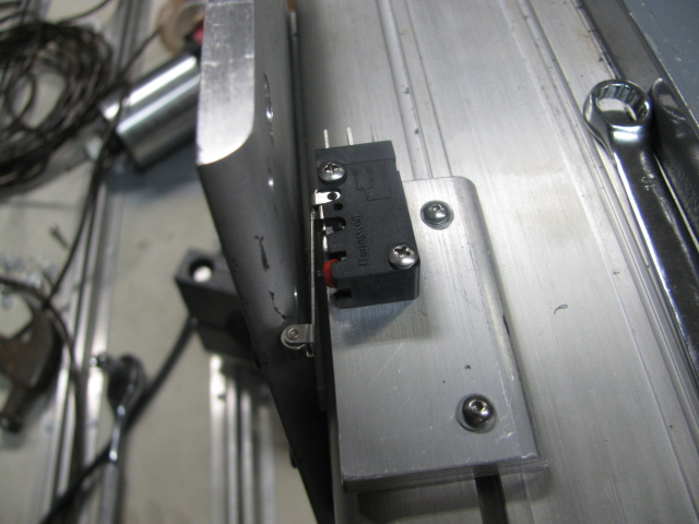
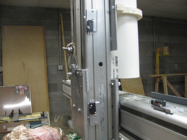
The last few days, I have been installing limit switches and making the mounting for them. The Adept modules have little races to mount things, and I used them. It happens that a 4-40 nut just fits into the groove. I was looking through some old junk and ran across an old microscope base with nice V ways, and I thought that this would work well for a manual Z axis adjustment for the cutter. It will be easy to zero the Z axis by just turning a knob, I am going to mount it to see if it will work out, some pics. of the start of the micro switches and the axis addition. Bob.Attachment 5354Attachment 5355Attachment 5356
-
Thank you PJs, for the thank you. Today I finished the mechanism to adjust the Z axis manually, and it looks like it will work, unless, of course, the casting cracks. It is not made for this sort of thing, it is a microscope adjustment mechanism, but it might. If it doesn't, oh well, back to the drawing board. It seems quite strong, but the vibration could change that, I hope it doesn't. Here is a short video. I have my buttons in the mail from Prolabs, they look very professional, can't wait to hook them up. Bob.https://www.youtube.com/watch?v=GAHuH0EH3_c
-
3 Attachment(s)
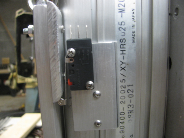
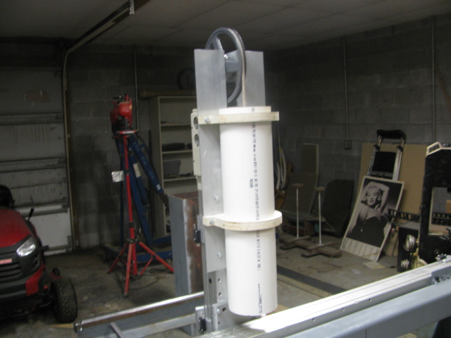
Here is the counter weight assembly finished, took 15 lbs. to counter. Also the Z axis micro limit switches. Bought the fabric for the covering of the ways, digging out my sewing machine. Any one know how to load the bobbin? Attachment 5401Attachment 5402Attachment 5403https://www.youtube.com/watch?v=3F8A4VYxBvE
-
1 Attachment(s)
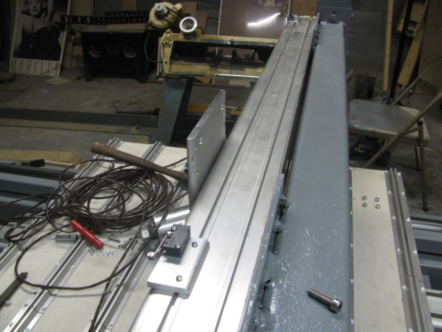
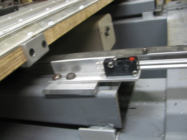
Today I mounted the X axis limit switches. I realized today that I made a mistake in estimating the travel of the x axis when figuring the length of the way cover. It turns out that I have to raise the machine 14 inches to accommodate the length of the cover, oh well, back to the drawing board. Bob.Attachment 5428
-
A pleasure! Thanks for the regular updates on a great project! Adding the microscope slide is excellent, very precise rack and pinions they have. Sure you will figure out a brake of some kind. ~PJ
-
Thank you Jon and Pjs, I will just keep trudging along until I am done. I am involved in raising the machine 14 inches to allow for the way cover, oh well, it will be better higher anyway, then I will get back to the wiring of the machine. Bob.
-
1 Attachment(s)
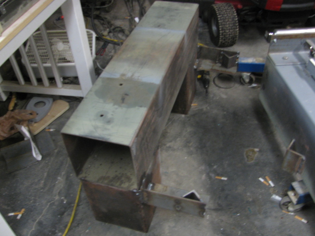
Well, let me tell you what I have been doing. I attempted to cut and weld the leg extensions and then my welder failed. After 2 days of trouble shooting, I found the problem. It was a simple set screw that fell out of the hose between the gas solenoid and the hose leading to the torch. This is a MIG, by the way. I remember when and where it happened. I had just installed a new .030 in. tip and started to weld and it welded perfectly. Then I decided to pull on the dolly that houses the wire feeder to move it to a better position, and their is where it happened, but I didn't know it at the time.Attachment 5559 The fitting that allows the gas from the solenoid to go into the hose was displaced 1/4 inch and blocked the gas from going to the hose. I took everything apart, blowing on each section and finding that there was no blockage until I got to that fitting. I also repaired two gas leaks along the way. Thinking it was a bad solenoid, I was waiting until Monday to go buy one for 150.00. After thinking about the fact that it might not be the solenoid, I looked further and there it was. The fitting was missing a setscrew, and after looking more closely, I saw the groove where the gas should go and it was blocked, that is why there was no gas to the torch. Two O rings later, and a setscrew and I was back in business. So now I have one set of legs welded and while I was jacking up the router, the jack ram started spewing hydraulic fluid all over the place, so there I go down to Harbor freight to buy another ram. Tomorrow maybe I will have the legs installed to a new height. The welder welds so nice now, and hopefully the cherry picker will actually pick. Also the extensions that you see on the legs are for casters. Got my buttons from POLABS and a pendant, both are beautiful and will look nice on the cabinet. So, that is what I have been doing. Here is a picture of the raised legs. Bob.
-
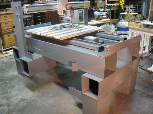
1 Attachment(s)
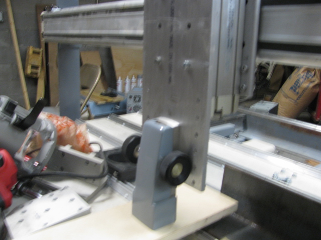
OK, I can now continue with the build. The next thing is the way covers. I will have to pull out the sewing machine, hope I can figure out how to wind the bobbin. Here is the raised machine. Bob.Attachment 5572
-
looking good. But I can't help wondering if all of those large hollow sq tubes that make up the frame will become resonating chambers. I am pretty sure I can already hear a machine that will deafen everyone around.
Foam filling may help if the time comes but for sure capped ends and oil soaked fine sand packed into all cavities will kill of many decibels plus effectively turn the frame into a dead solid block which will serve to cancel out much of the possible harmonic or possibly ultrasonic resonance if it occurs.
-
I really won't know until I run the machine, but this is not a stepper system, this is a servo system, so no buzzing of the servos. If you are talking about the cutter, well we shall see. The vibrations will have to go through three layers of wood and then into the tubing. Resonance is a funny thing depending on the freqs. Don't know yet. If all else fails, I could make a pipe organ out of it. Thanks. Bob.