Free 186 More Best Homemade Tools eBook:  
Get 2,000+ tool plans, full site access, and more.

User Tag List

Page 2 of 4 FirstFirst 1 2 3 4 LastLast
Results 11 to 20 of 36

Thread: Converting a drill press to mill-drill

  1. #11

    Join Date
    Feb 2014
    Posts
    17
    Thanks
    4
    Thanked 21 Times in 7 Posts

    master53yoda's Tools

    Asian X-Y table modifications

    Converting a drill press to mill-drill-x-y-1.jpg

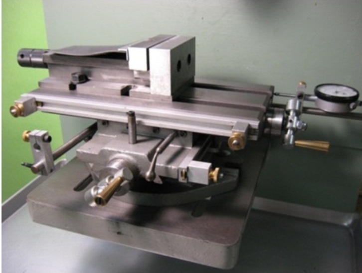
    For this conversion I was able to locate an early American made table that I will install a set of DROs on. When I am not able to find an American made table and must use an Asian table, there are items that need to be modified to bring them up to par. They are excellently described on Nick Carters site. These explanations are from that source. I have excerpted pictures and some of his write up. His site includes how to do the modifications on the leadscrew. This material is being used with his permission.
    Source Cross-Slide Table Modifications I have made my comments in blue
    +


    Gibs Not necessary but i use brass gibs whenever possible
    The original gibs were steel and not suited to wearing in for that nice silky movement. I just made exact duplicates in brass. Over time they have improved the action noticeably.

    Dial Gauge Control for Table Movement this is replaced by the DRO

    With the poor leadscrew dials it was just about impossible to move the table with any precision. Since I wanted to drill accurately located holes, this was important. I tried mounting dial gauges with magnetic bases and arms but found it surprisingly difficult to get them placed just right. Constant headache. So here's my solution.

    Converting a drill press to mill-drill-ph-3.jpg
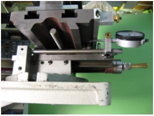
    Photo 3: Y-axis Dial Gauge


    Photo 3 shows the mounting blocks and rods installed to hold dial gauges for measuring table movement in the X and Y directions. This eliminates any uncertainty because of backlash, loose gibs or a sloppy lead screw.


    Table Locks
    Locating the table precisely is not much help if it's going to jiggle around whenever the tool hits the work. So locks are needed to make sure it stays put.

    Converting a drill press to mill-drill-ph-5.jpg
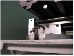
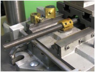
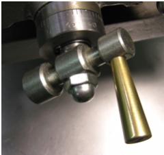
    Photo 5: Y-axis Table Lock

    Photo 5 shows the extra gib holes drilled and tapped to take the ball handled locking screws. Once tightened, these keep the positioned table perfectly stationary. Very accurately spaced holes can be achieved.

    Thrust Bearing This improvement is almost a necessity

    I wanted to try light milling on the drill press since I didn't have a milling machine at the time. Experiments showed that there was just too much uncontrolled table vibration. For milling, the table should be as jiggle free under movement as when locked down. Once the gibs are properly adjusted, the only other component allowing uncontrolled motion is the lead screw. I started with the thrust bearing where I assumed (incorrectly) all the backlash to be.

    Converting a drill press to mill-drill-7.jpg
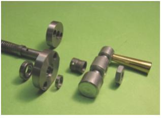
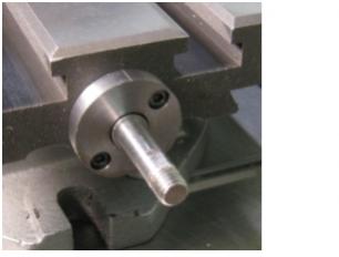
    Photo 7: Original and New Thrust Bearings

    Converting a drill press to mill-drill-8.jpg
    Photo 8: Mounted New Thrust Bearing

    The original was just a steel disc with lots of non-adjustable backlash determined by how (not very) close to it the outer sleeve was pinned to the shaft during manufacture. The new one carries a ball bearing and spacer so the backlash is determined by the precision of the ball/race fit. If I were doing it again, I'd make this block thicker and mount two ball bearings with a spacer between and some bearing preload. It's amazing how much play there is in a single ball bearing. I never thought of this until later but couldn't have done it originally anyway because I was fitting it to the original leadscrew and was limited to the thickness of the original thrust plate.
    The new plate had to be larger in diameter to make room for new mounting holes outside the bearing recess.

    Leadscrew and Nut This improvement is almost a necessity
    The new thrust bearing helped but didn't completely eliminate the problem. The table could still be moved perceptibly back and forth. So I took the whole thing apart to have a look at the leadscrew assembly.
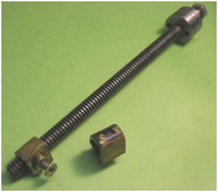
    The original leadscrew has a 1/2-10 Acme thread and a very loose nut. The second nut in Photo 9 shows how I tried to tighten up this fit by adding screws to bear on the leadscrew. It was a half-vast fix and didn't really work. Making an adjustable nut for an Acme thread is problematic and, anyway, the cost of a 1/2-10 Acme tap is close to $100. So back to the drawing board.

    Converting a drill press to mill-drill-9.jpg

    Photo 9: Original Leadscrew Assembly


    Here is the heart of all these modifications, a new leadscrew and nut. The leadscrew is 1/2-20 threaded rod and the thrust bearing end was machined completely on the Taig lathe. For some reason, at the time of making this particular part I made step-by-step photos which are in the appendix for those who are interested. The nut is adjustable following the practice of the Taig CR mill and is somewhat larger than the original which is shown for comparison. Also shown is one of two spare blanks made in case of a screw-up along the way.

    Converting a drill press to mill-drill-10.jpg
    Photo 10: New Leadscrew and Nut Assembly

    Dials and Handles Nice improvement but not necessary with DRO
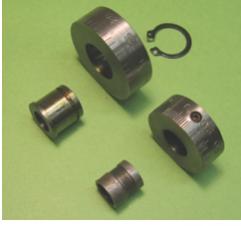
    The original dials were intended for a 10 pitch leadscrew and were too small. The new ones have 50 divisions to suit a 20 pitch leadscrew and are the same size as the new thrust bearing carrier.

    Converting a drill press to mill-drill-11.jpg
    Photo 11: Original and New Dials

    Converting a drill press to mill-drill-12.jpg
    Photo 12: New Dial Mounted

    The dial carrier was made the same length as the original pinned spacer. The new dial is held in place by a circle clip which is bent and rides in a groove wide enough to let it press lightly on the dial so as to damp its rotation.

    The increase in leadscrew pitch means more turns per inch table travel so rotating handles ease the wear and tear on fingers.


    Again I would like to agknowledge that the above post is located @ Cross-Slide Table Modifications in its complete form. The details for makeing the Lead screw are at that location.
    Attached Thumbnails Attached Thumbnails Converting a drill press to mill-drill-x-y-1.jpg  

    186 More Best Homemade Tools eBook
    Last edited by master53yoda; Feb 28, 2014 at 01:29 PM.

  2. The Following User Says Thank You to master53yoda For This Useful Post:

    jere (Mar 26, 2015)

  3. #12

    Join Date
    Mar 2012
    Posts
    7
    Thanks
    0
    Thanked 5 Times in 1 Post

    vibration and filling

    Quote Originally Posted by master53yoda View Post
    ...fill the column and the base with solid cement.
    In my research on the vibration problem I found this about epoxy-granite filling. What are your thoughts on this?

    2000 Tool Plans

  4. #13

    Join Date
    Feb 2014
    Posts
    17
    Thanks
    4
    Thanked 21 Times in 7 Posts

    master53yoda's Tools
    I might give that a try on this one it looks like it should work real well, I'm wondering what kind of mass it adds problably close to what the cement does I would think, I will need to do a bit more research before I do it for sure.

    Art
    Last edited by master53yoda; Mar 2, 2014 at 12:51 AM.

  5. #14

    Join Date
    Feb 2014
    Posts
    17
    Thanks
    4
    Thanked 21 Times in 7 Posts

    master53yoda's Tools
    I have had a few requests for an explanation of the column and spindle gibs. I havn't gotten to that part of the conversion partially because it takes a complete tear down and some time and... '[;.,/ ... to get them in

    The gibs when installed and adjusted remove the slop that is in the drill press head that causes much of the frustration found in using a converted drill press even when the bearing issues are removed and the column filled with cement etc..

    This modifaction is what allows a face mill to be used and still have a clean surface, I have run a 3" face mill with out issues with the gib modification completed. The manufactured mill-drills are machined to a closer tolerance then the drill presses are and without this mod you can never get the quality cut that is available in the higher end mill drills. You may find that the brass bolts mentioned at the end of this write up that are used in the interm while makeing the gibs, may work for you if you aren't going to use face mills or large diameter boring activities.

    I have tried a couple of different positions on the gibs. I have found that the very back of the column is the best location for the column gibs and the very front opposite the pinion on the spindle. The design is the same for both.

    Converting a drill press to mill-drill-column-gibs.jpg

    I have tried a 120o separation using 2 gibs on the column but have found that it must be almost perfectly adjusted or it cants the head and makes it very hard to keep the machine trammed. I do use it on the column if I cant reach the column lock that is in the center of the Gib I then use the 120o gibs with the one that I can get to as the column lock.

    in the drawing above there is a second gib above the journal. On some of the larger heads I have had to add that Gib in order to get the last of the forward slack out of the head. This conversion is a 17" head and that is about where I end up using the upper gib as well as the lower one. I have found that it isn't a good idea to place the lock screw in the upper gib. I cut the gibs .125 shorter then the total space between the journals and I have made the column gibs from the old lift rack successfully. I have also made them out of brass if using a head with a short quill travel.

    I make the spindle gibs out of brass as they are moving a lot more. The method I have used to cut the cove to match the spindle diameter is to mount the brass casting up against a block in the mill vise. As a gib in the interm I use a brass 5/16 bolt in the hole in the front of the head that will later be used as the quil lock. This could be done on the column as well but you would definatly need to place one above the journal in that case.

    I will add pictures to this write up as I proceed with this modification but this will help anyone that is in the wondering mode about the gibs.

    Till next post


    Art
    Attached Thumbnails Attached Thumbnails Converting a drill press to mill-drill-column-gibs.jpg  
    Last edited by master53yoda; Mar 3, 2014 at 01:12 PM.

  6. #15

    Join Date
    Mar 2012
    Posts
    7
    Thanks
    0
    Thanked 5 Times in 1 Post
    Very clever. Although I do, most won't have the ability to cast. The cord depth isn't deep. I wonder how well the piece would work if you were to dress the approximate contour with with a file, then lap it against the spindle with very fine (read "thin") sandpaper, and finally cut a relief along the axial center about 1/2" wide x .005" deep? Maybe rather than the contour of the spindle, just file a "vee" that's almost flat having an included angle of contact of perhaps 165-degrees...?

  7. #16

    Join Date
    Feb 2014
    Posts
    17
    Thanks
    4
    Thanked 21 Times in 7 Posts

    master53yoda's Tools
    Quote Originally Posted by toolman View Post
    Very clever. Although I do, most won't have the ability to cast. The cord depth isn't deep. I wonder how well the piece would work if you were to dress the approximate contour with with a file, then lap it against the spindle with very fine (read "thin") sandpaper, and finally cut a relief along the axial center about 1/2" wide x .005" deep? Maybe rather than the contour of the spindle, just file a "vee" that's almost flat having an included angle of contact of perhaps 165-degrees...?
    That would work fine. When Cuttting the contour in the gib i do it with a boring head in the mill/drill using a brass screw as a gib to take the slop out of the spindle, it has to be fairly tight but does work ok. You could start with a 3/4 or 1" x 3/8 piece of stock and use the V and be fine as long as the V stayed parallel, the reason for the contour is just to give more surface area so that gib doesn't have to be any tighter then necessary when performing a z axes process like when using a boring head and still lock effectively with the center locking screw.

    Was it reasonably plain to see what i was doing without pictures???

    Art

  8. #17

    Join Date
    Mar 2012
    Posts
    7
    Thanks
    0
    Thanked 5 Times in 1 Post

    Gib pictures?

    Quote Originally Posted by master53yoda View Post
    ...Was it reasonably plain to see what i was doing without pictures???
    Reasonably. A picture is worth a thousand words.
    Last edited by toolman; Jul 13, 2014 at 06:59 PM.

  9. #18

    Join Date
    Mar 2012
    Posts
    7
    Thanks
    0
    Thanked 5 Times in 1 Post
    Art, how's it going? You haven't posted in a while.

    Mike

  10. #19
    kbalch's Avatar
    Join Date
    Jun 2012
    Location
    Clermont, FL
    Posts
    5,034
    Thanks
    2,275
    Thanked 531 Times in 383 Posts
    This thread has been moved to the Must Read subforum. Congrats (and thanks) to master53yoda for making such a valuable contribution!

  11. #20

    Join Date
    Jan 2016
    Posts
    2
    Thanks
    0
    Thanked 0 Times in 0 Posts
    Thanks for the knowledge and info.

    Looking to fix my clausing 16 inch drill press.

    AM I correct in saying the lower bearing that "rides" up and down with the quill handle is the one to change out. Quill depth brass bearing/ Is this the part you may bore out to fit a better bearing? If so I need to find something around 20ish wide.

    On my clausing I think there is only one and the top one at top of drill press head?? Would it also help to change that one out as well.

    I am putting a 1/4 reduction pulley setup on which is going to give my a TON more torque!

    INSERT After looking at your drill I don't see a quill setup like mine?? Kind of confused here?
    Last edited by sandmanxx; Jan 25, 2016 at 07:34 PM.

Thread Information

Users Browsing this Thread

There are currently 1 users browsing this thread. (0 members and 1 guests)

Bookmarks

Posting Permissions

  • You may not post new threads
  • You may not post replies
  • You may not post attachments
  • You may not edit your posts
  •