
 LinkBack URL
 About LinkBacks

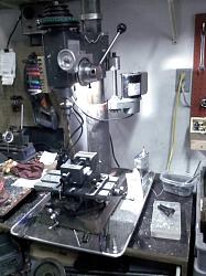
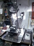
I have successfully converted multiple drill presses to mills. There are a few things that MUST be addressed.
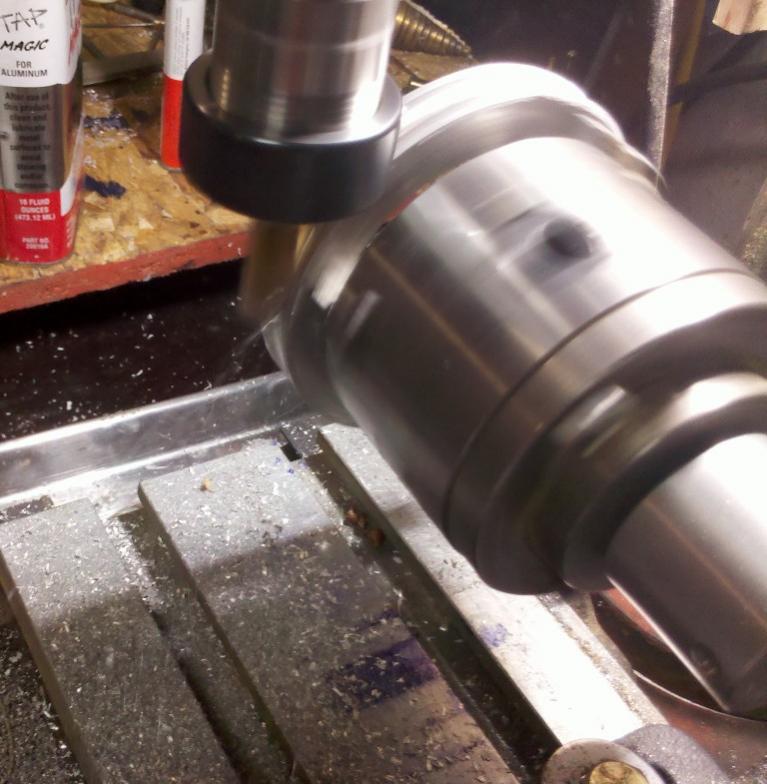
Replace the lower spindle bearing with an angular contact double row bearing . This resolves the side thrust issue on the bearing.
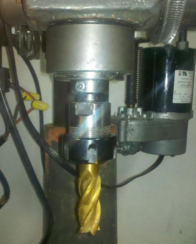
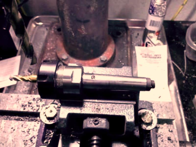
I go to a ER25 or 30 series collet systems with the proper Morse taper and either use a draw bar or a lock pin to retain the taper.
I have found that the table on the drill press isn't ridged enough for mill work; this won't be an issue if the table is rigidly mounted on ways. Most drill presses mount the table on the column and the end result isn't rigid enough. I cut the total height down; remount the head using a gib to make the head more rigid on the column I also gib the spindle to remove the excess slack in the spindle. I then mount the x y table directly to the base. If i can't find an older American cast 6x 12 or 18 x-y table I buy an asian table and upgrade the bearings and tighten the scroll nut to remove as much backlash as possible from the lead screws.
some method of locking the spindle, I use the center point setscrew on the added gib if there is room for it.
The items below are nice but not absolutely necessary
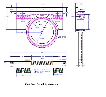
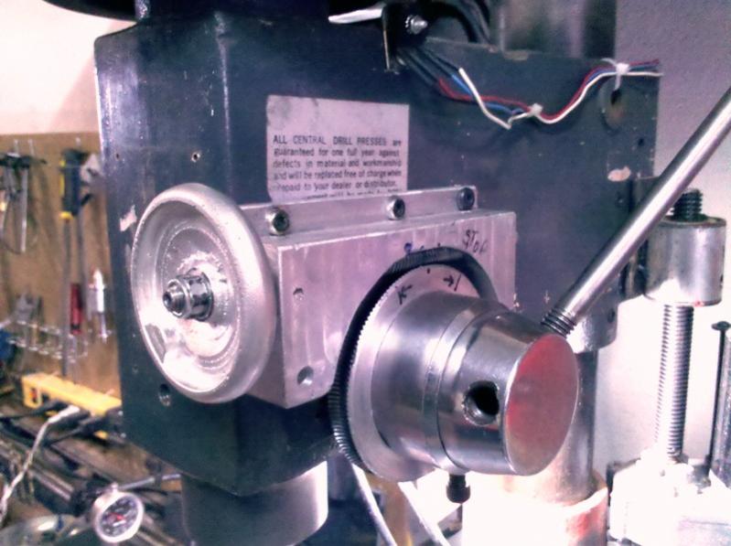
A fine feed on the Z axis is pretty hard to do without, I cast mine out of aluminum and use brass bearings for thrust adjustment for the fine feed, It is also designed to put a stepper motor for CNC if desired. I also go to external springs on the spindle to remove the play between the spindle and the z axis drive as the return spring on a drill press leaves down backlash on the spindle.
I go to a high end 1.75 to 3 hp treadmill motor (the ones that are rated at 4000 rpm or less) these will deliver a sold 3/4 to 1.5 hp in the operating range that they will be used on the mill. I normally limit the spindle speed to nothing higher then 3500 rpm and use a 3 or 4 step reduction pulley set. They will power tap and handle 3" face mill.
I normally will also set them up with a DRO
I use a z axis drive (the angle motor off of a treadmill) to raise and lower the head on the column and also use a 1/2 or 5/8 auxiliary shaft to retain alignment on the column.
I will be adding other items as time goes on, the first 2 or 3 additions will be fairly quick


 Reply With Quote
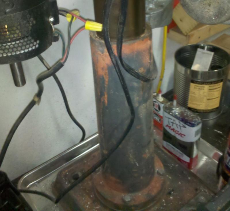


Bookmarks