
 LinkBack URL
 About LinkBacks


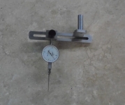
This is a dial indicator attachment I designed for use in the milling machine for indicating small holes and tramming the mill, after a few hours horsing around in CAD I came up with this tool.
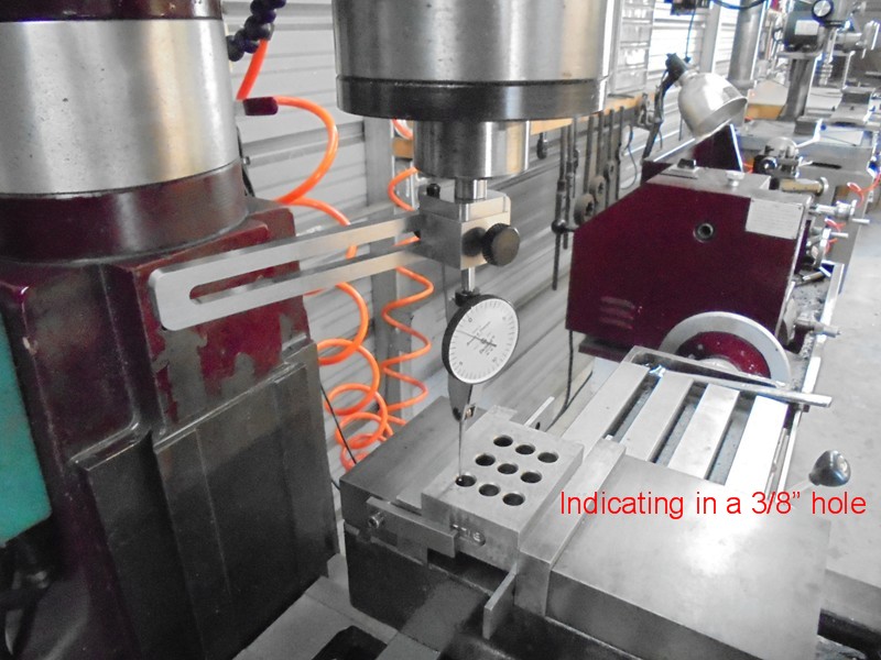
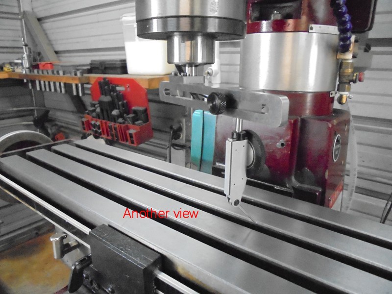
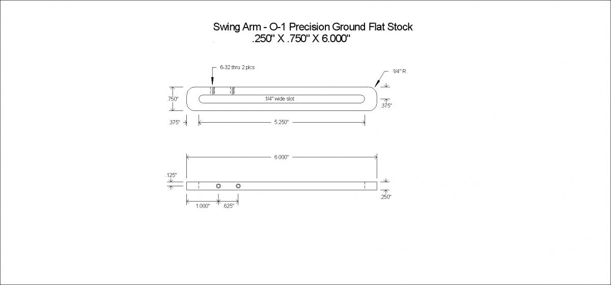
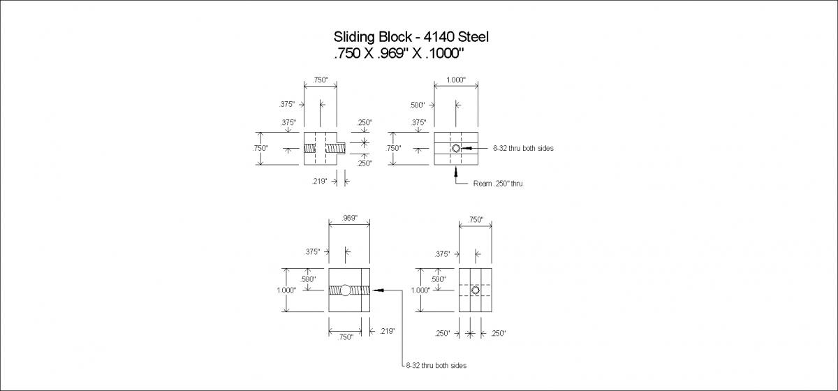
The dial indicator is attached to a Sliding Block that has a machined tongue with a knurled locking thumb screw, this tongue fits very nicely into a milled slot in the Radius Arm, the Block will slide in and out to whatever radius is needed, (from 0 - 5”, the arm can be made longer if needed), the Block will slide all the way inward toward the spindle which positions the dial indicator directly on center of the machine spindle, (it will also go past center about a negative ½”) this is the key feature that makes it easy to indicate a very small hole in without the need for a bunch of universal joints, stems, knuckles Etc. this tool is very rigid and works extremely well.
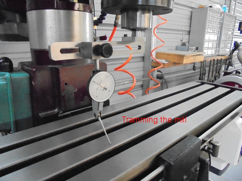
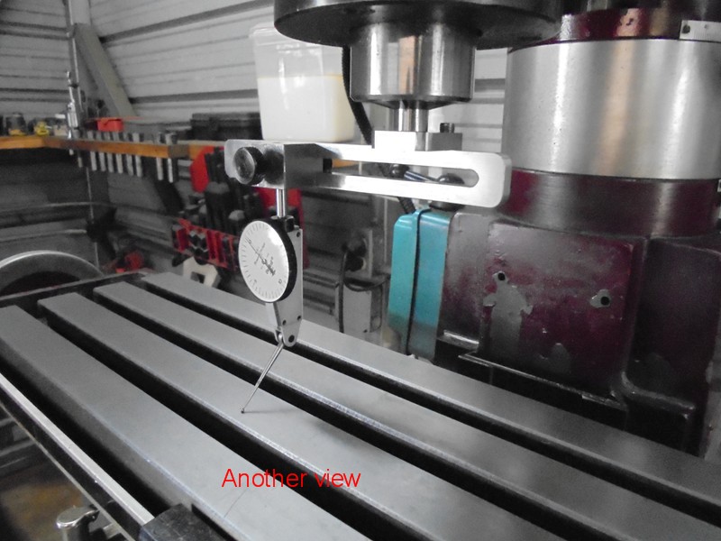
Tramming the mill head in is no different than usual, just loosen the Sliding Block adjusting screw and slide the Block out as far as you need then relock the adjusting screw, sweep the head in as you normally would.
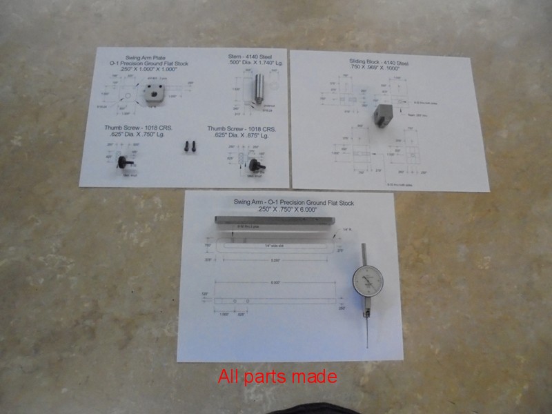
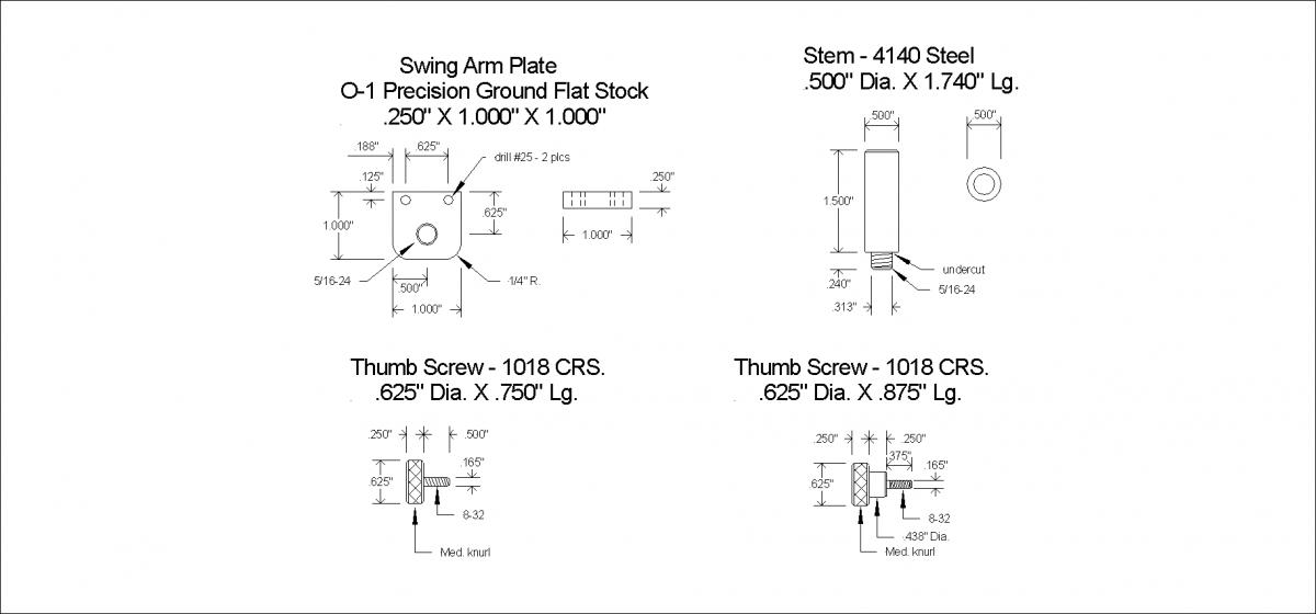
The unit has a ½” diameter stem 1 ½” long to fit into a collet or drill chuck, the entire unit was constructed from O-1 precision ground flat stock, the two knurled thumb screws were made from 12L14.
Below are some photos of all the machined parts, also photos of the tool being used to indicate in a small hole and the tramming of the mill along with 3 drawings.
As always thanks for looking
And happy machining
Doug
Finished Parts
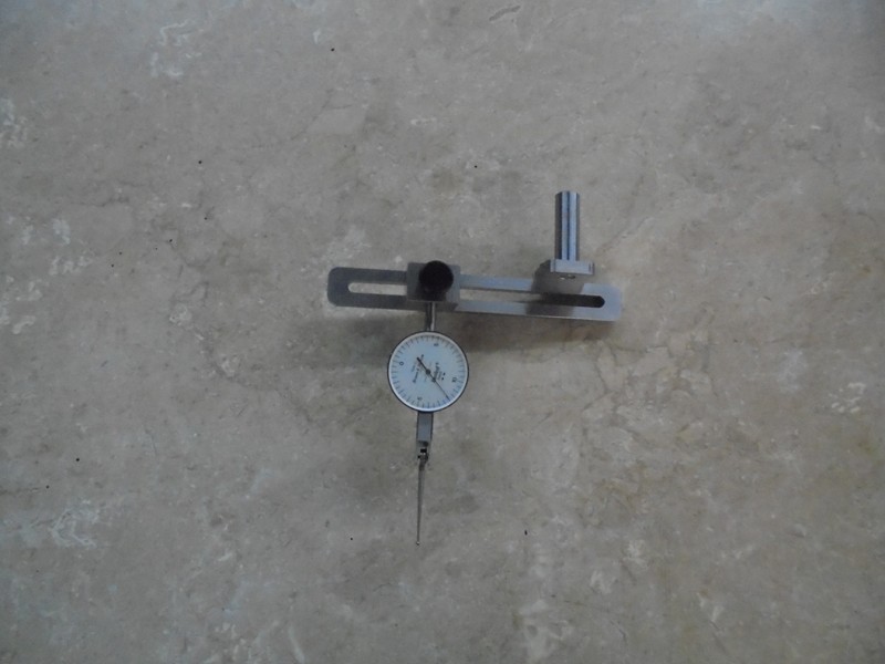
Completed unit
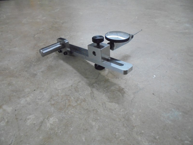
Different Angle
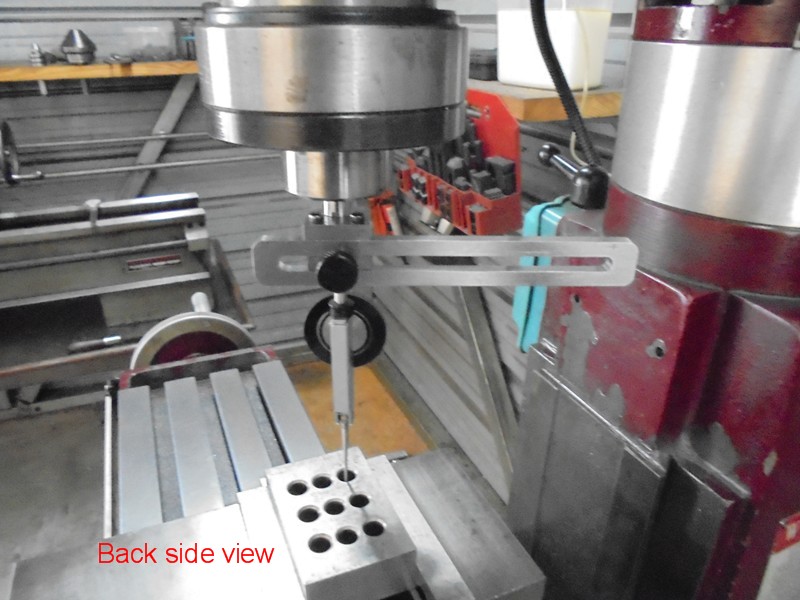
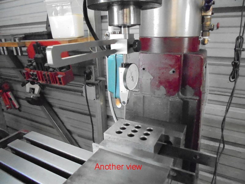
Indicating in a 3/8" hole
Another View
A Different View
Sweeping the Mill Head
Another Angle
Yet Another Angle
Here are the 3 drawings, just right click then left click save picture as, there in .png format


 Reply With Quote


Bookmarks