 LinkBack URL
 About LinkBacks
Dice dotting machine.
Previously:
Portrait of a woman made from 30,000 dice


Dice dotting machine.
Previously:
Portrait of a woman made from 30,000 dice

HomemadeTools.net founder (2012) and CEO
Join thousands of us, and start building your own tools today.


Have to wonder, why is the pattern so random? I would think it would start at one side and move to the other. There must be a reason I have not thought of...


CAM software for generating toolpaths for CNC milling do not usually produce the most efficient paths, often jumping about like this dice machine. There seems to be more work needed on the algorythms. Most often different CAM programmes produce different paths for the same object.Originally Posted by hemmjo

Yesterday I was making some printed circuit boards using isolation milling, the previous week I spent some time checking out various dedicated PCB generating software and outputs of each were quite different in terms of the tool paths.
Click for full size.
First test of isolation milling a PCB.
PJs (Feb 7, 2019)

In the foreground is a five-spot die with only four of its spots painted.
Until I saw that, I thought it was using as its algorithm: paint the nearest unpainted dot.
Given that the array of dots-to-be-painted is seemingly randomly arranged, puzzling out a simple algorithm that paints every dot and knows when it's done is a very interesting and seemingly complex problem.
The other puzzle is why the dots are arranged so randomly. Surely the depressions are made with some sort of automated machine so one would expect a more patterned arrangement.
PJs (Feb 7, 2019)
Perhaps to compensate for uneven weights ensuring that dice manufactured together will not roll the same numbers more frequently than others?
To keep the die balanced the spots are drilled such that spots on opposing faces always add to seven. Presumably that was accomplished when the dice were spot drilled in an earlier process. The random arrangement of dots to which I referred is the arrangement of the spots facing upwards under the paint dispenser.
A video showing the entire process of die construction would be helpful.
PJs (Feb 7, 2019)
I was more referring to the irregularities in weight from the manufacturing process itself adding to off balance (cheap) dice
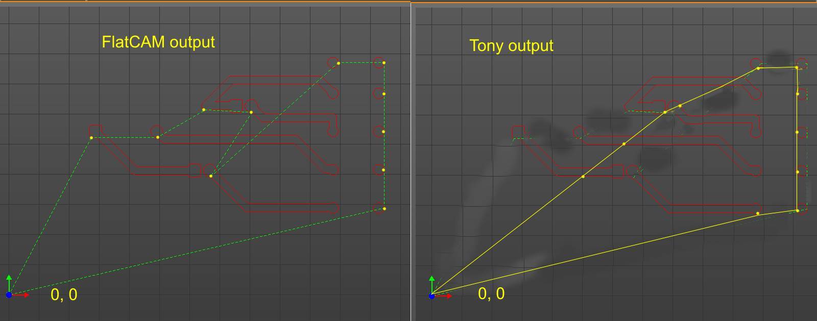
Here is a pic showing the toolpath output from a PCB dedicated CAM programme (Left) and a human (me) variation (right). By way of explanation to those unfamiliar with CNC toolpaths, the red lines show where cutting has to take place and the green dotted lines on the original and yellow on my version are where the tool travels when lifted off the work piece. I have added yellow dots where the tool touches down to do the milling. So to follow the path we start at the origin (0, 0) travel along the green or yellow lines until the first dot where the tool is dropped and starts to cut and then follows the red path back to its starting point where it lifts and moves on to the next dot. Following the red paths cannot be improved because that all has to be cut. However, to optimize the whole process we need to calculate the green path to give the shortest total length. It only took me a few seconds to see a better way. It appears that the software applied the algorythm "go to the next closest unmachined track" as Marv mentioned. At first sight that might seem like a pretty good way of doing it, but we can see that even for this very simple problem it does not produce an optimum path. On the other hand, human brains tend to look at the whole picture and look ahead.
This was a very simple example just imagine the complication involved in determining optimum tool paths for a complex part, say a cylinder head for a V8 machined from the solid on a 5+ axis mill. The human brain finds that rather difficult. Tool changes are thrown into the mix with complex parts, so in addition to finding the shortest path we need to consider whether it is better to follow a non-optimum path in order to save tool changes. Things get complex real quick. With multi-axes machines a given operation can often be accomplished with different axis, so that adds further to the complication.
Much work is being done with improving software for determining tool paths because non-optimal paths slow the total job time and that costs money.
Click for full size.
Last edited by tonyfoale; Feb 6, 2019 at 11:58 AM.
This is closely related to the traveling salesman problem...
https://en.wikipedia.org/wiki/Travel...lesman_problem
an NP-complete problem and one of the most difficult to solve. AFAIK, no general solution exists.
For the benefit of those unfamiliar with the problem, I'll quote the description from the above referenced Wikipedia reference.
"Given a list of cities and the distances between each pair of cities, what is the shortest possible route that visits each city and returns to the origin city?"
(Most descriptions of the problem specify that each city is to be visited only once.)

I agree with Marv on the randomness of the layout. Wondering if there is not some kind of vision system in the print head...the cables on the right may be part of that feed?? It appears to me that each die face is printed complete before moving at what seems to be a random jump to an adjacent die or to another area. I get the path problem but from a manufacturing standpoint I don't understand why there are no clamps unless a vacuum is used. Also note at :06 the front row seems offset a bit from the subsequent rows. I would think a loaded rack would need at least 5 sort/print passes plus drying time.
Even with modern AI it takes a while to optimize a path for even a salesman.
Good thread, Thanks!
Always do right. This will gratify some people and astonish the rest.
Mark Twain
There are currently 1 users browsing this thread. (0 members and 1 guests)
 Posting Permissions

 Reply With Quote
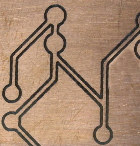


Bookmarks