 LinkBack URL
 About LinkBacks
I was wondering about something and thought someone here could give me insight.
What would happen if a fly cutter set up for right hand turning was used for left hand turning?


I was wondering about something and thought someone here could give me insight.
What would happen if a fly cutter set up for right hand turning was used for left hand turning?

To clarify more, is the tool holder for right hand turning offset in such a way where there would be vibrations issues or something else potentially going on with a left hand tool inserted in it?


The difference of right or left is partly secondary. More right hand cut cemented bits [AR] are sold/ used/ on hand, kind of determining why fly cutters are also right hand cut, like endmills, drills, reamers and most everything else.
But I find left smaller left hand [AL] on sale every once in awhile...so here is my spin on flycutters.
They are slotted as shown on the drawing, perpendicular to holding spud at about 1.75-2.0x deeper than tool is square. Every so often I add a set screw perpendicular to slot, a 'jack' to maintain cutter incline angles. Instead of set screws as bit holders, regular socket cap screws, with customization in length make a hex easier to find. Also flat tips make tool projection simple to adjust, compared to the divot from cup points.
I think your right hand/ left hand question bears on orientation in the slot. Either way the side cutting needs the front and side clearance to operate; just like a lathe tool.

Sincerely,
Toolmaker51
...we'll learn more by wandering than searching...
Thank you for the information it is very helpful.
I was thinking of design for balance having smooth operation at higher speeds. I had in mind that a tool holder for RH turning was weight balanced differently than a LH tool holder. I seems that the diagram you posted states the design is mostly for convenience not balance.
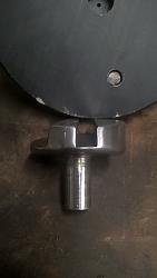
I modified a 4" fly cutter I have to accept a 3/4" square CBN/PCD round cutter I made and it has a vibration at 600 rpm which is quite noticeable. I do not want to use it like that so I decided to have a go at making a fly cutter.
I have a 3" x 3" chunk of round bar and wanted to make a tool holder for my vertical mill to finish intake and exhaust mounting surfaces on cylinder heads among other things smaller in scope. I will use this with an R8 to 5/8 x 11 adapter. My thoughts are to face off both ends of the bar stock, drill and tap one end then mill a 3/4" slot at approximately 15 degrees of angle with set screws to finish.
My intention was to mill the slot on center but after looking at the diagram you posted that may not produce good results. Any suggestions here would be appreciated.
I see some successful fly cutters are milled on center, or at least they look like it. The PCD/CBN cutter holders I made are milled for about 7 degrees of negative rake.
I want to use a standard carbide from time to time for milling an intake mounting surface which has an over hang or ledge for valve cover mounting. There are certain applications where I do not want to get into the lip with a round cutter. I believe the carbide holder is typically at a positive rake. I want the fly cutter to work well with either positive or negative rake cutters in it.
In my experience it is an unbound convention that flycutting tips run on center. Endmills cut on the apex, lathes run on the apex; so I think it was just a case of copycat to deem flycutting be so. BUT, endmills and lathe tools benefit from helical or mechanical equivalent top rake to generate a chip. Many forget to provide that for flycutters. And lathes will still cut below center, above not so much! Top rake isn't built into brazed tools.
The centered cut works as expected, the variation works better; less chatter at higher feed and reduced noise from the machine head.
Long ago, we needed aluminum sections about 7" wide, 2" thick, and a 4" wide trough down the middle. It wound up .8 deep, with a .3 radiused corners. At 10" long and required surface finish, bandsawing was out. I made two solid, brazed carbide flycutters, with integral R8 shanks. Basically identical, the first was .100 under diameter and .05 larger radius, second on size for width and radius. #1 ran .500 deep in one pass. #2 ran .8 deep, then retracted [up] to blend the undercut. The seat [1 per cutter] for carbide blank was .7" below center. Those were roughly profiled form tools, silver soldered in place. Then I used just a overgrown spindex to create the diameter accurately, based off the spindex centerline. Radii were freeform ground, and blended by hand.
I don't recall what RPM or feed rate they ran at, but the quarter sized chips flew over 10 feet.
Sincerely,
Toolmaker51
...we'll learn more by wandering than searching...
Wow! I would have liked to see that cutter in action! I take .003 cuts with my PCD and CBN tools on my mill with the 8" cutter.
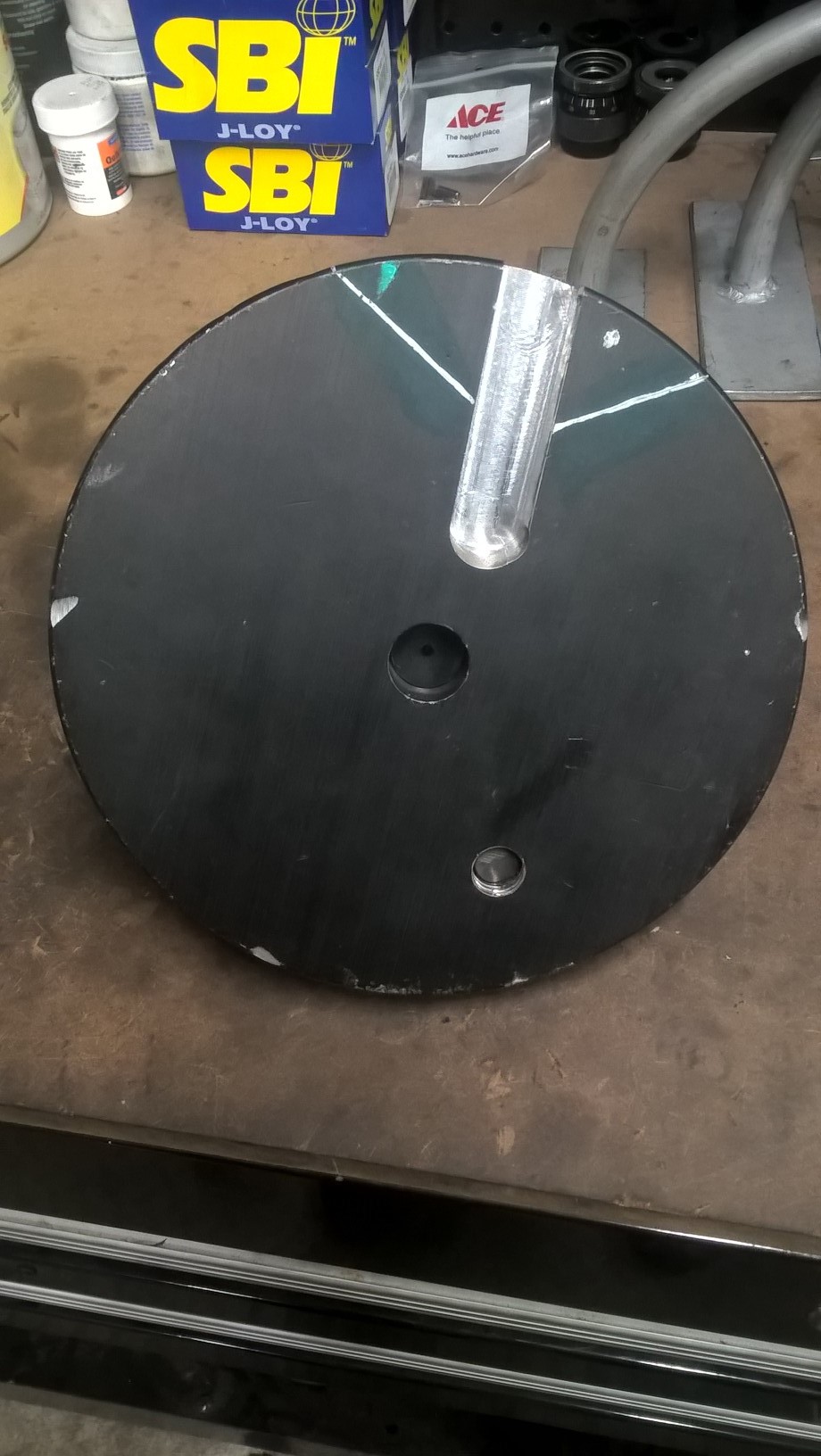
Pictured are two cutters I have. The larger is 8" and I use it for surfacing heads and blocks. The other is obviously a typical fly cutter. I say off center because of how these are configured.
Maybe they are set up as a compromise where the cuter tip will be on center having a certain amount of tool stick out and more or less stick out will work also?
What I want to do on my homemade fly cutter is mill straight across the center for tool holding.
Suburban Tool makes a fly cutter that appears to be on center. You can see it in the link.
https://www.subtool.com/st/fcs_fly_cutter_sets.html
We have a setup like that, but not Suburban. Uses holder like a boring bar and triangular insert. Works OK on steel, great on aluminum. Does what most big tools do in Bridgeport type mills, the inadequacy for heavy work. But that big shopmade cutter was Bridgeport only, so...
On center is the ordinary and common approach. Never seen proof that is THE combination.
Like the 'balancing cut'; a solid cylinder with a little projection is better balanced, than a odd shaped whatever - projection included. Flycutting is about good bearings, inertia, usually a high feedrate, with a cutter holding it's profile for an entire operation.
Sincerely,
Toolmaker51
...we'll learn more by wandering than searching...
In terms of balance, I have a larger fly cutter identical to the smaller one pictured and opened up the slot to 3/4" for the PCD/CBN cutter holders I made, At 600 rpm's there is a very noticeable vibration. I added we ight to the opposite end of the slot and it made it worse. I did not take the weight out yet. It obviously was not the right place for weight.
It seems like all the material taken out of the smaller type fly cutter has to make it way out of balance because the majority of the weight in it is bias to one side. Making one on center would have to be much closer to being balanced and could easily be balanced by adding some weight in the proper place.
I am not a machinist and make no claims to be. I build performance engines and professionally port and modify cylinder heads. There are machining processes involved some of which I do in my shop and others I farm out. I do all cylinder head operations here and deck blocks. Block boring, honing, main housing line honing, and rotating assembly balancing is farmed out. I have done all that when I worked for other shops but do not have the necessary machines here in my shop.
Having something spin in "balance" during a surfacing operation I would think has to produce better results than something vibrating. Smooth operation for any process has to be better for that matter, in my mind anyway. After balancing the 8" cutter, with a tool in it, I can spin that to 2k and it runs smooth. I do not use it at that rpm but it will go there and run smooth. Like I said the smaller one shakes the mill at 600. Smooth operation has to be better for my mill also.
I agree with the conditions you listed for a successful fly cutter. I am just saying having one spin smooth I would think would also help.
There are currently 1 users browsing this thread. (0 members and 1 guests)
 Posting Permissions

 Reply With Quote
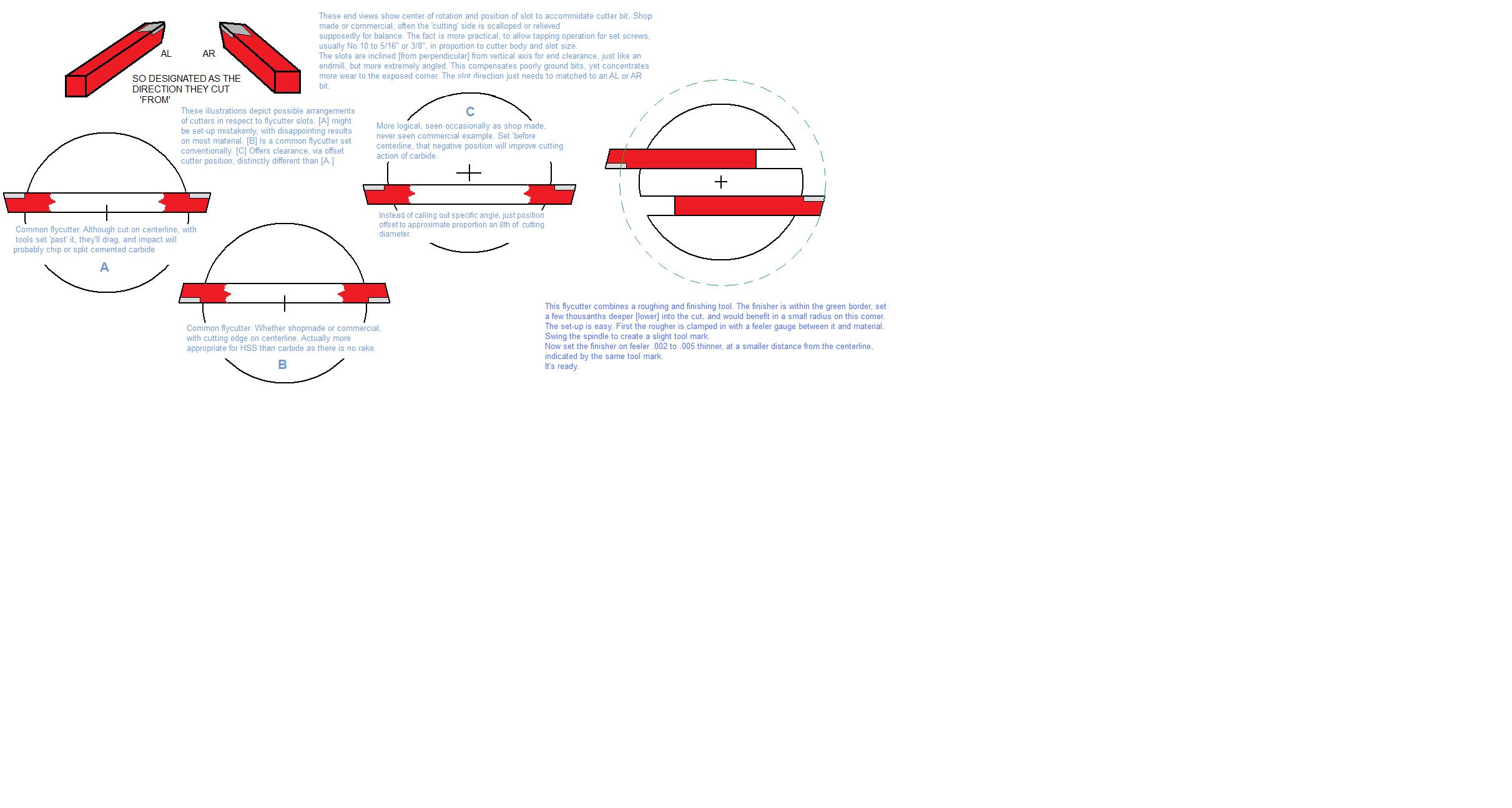

Bookmarks