Free 186 More Best Homemade Tools eBook:  
Get 2,000+ tool plans, full site access, and more.

User Tag List

Page 3 of 20 FirstFirst 1 2 3 4 5 6 7 8 9 10 11 12 13 14 15 16 17 18 19 20 LastLast
Results 21 to 30 of 198

Thread: Good advices for a newbie (threading tools lathe)

  1. #21
    PJs
    PJs is offline
    Supporting Member PJs's Avatar
    Join Date
    Sep 2014
    Location
    Northern CA
    Posts
    1,841
    Thanks
    8,337
    Thanked 1,118 Times in 718 Posts

    PJs's Tools
    This thread just got my thinking cap on...no cape or mask, C-Bag but thanks for your kindness!!

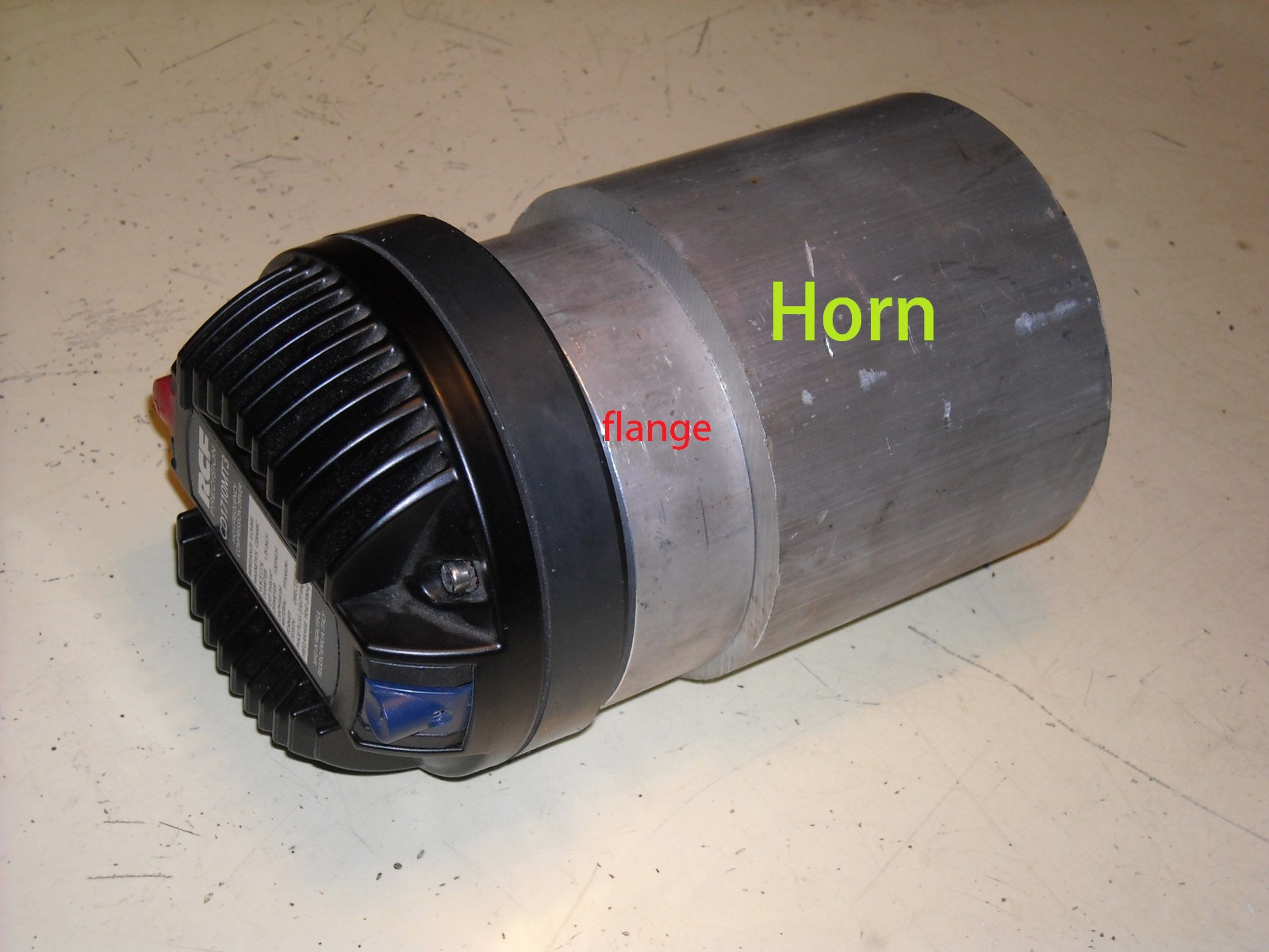
    Stefano: I downloaded the HF94 spec sheet which goes back to my question above about the total depth of the horn. The HF94 is 135mm which leads me to believe that you will add another piece to the flange above. ?? I would think the length is quite important to minimize the drop in pressure/db and maintain the dispersal and f response. This makes sense as the dispersion curves for the HF94 are quite good at 2, 4 & 8k and match the driver output well. Also agree they are hard pressed to prove the 20khz top end with a 10db drop off after 10k!!

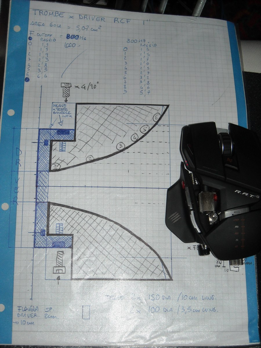
    What was interesting to me about the HF94 in the cross section view is the radial transition just above (no dimensions) exit port. I would imagine this straight section is part of the air motion chambering you speak of to increase the pressure into the actual cone. My hit is it is a tuned resonance chamber 1"ID x X"length (1/f function) to achieve greater pressure prior to the cone.

    This is where I am at a bit of a loss to calculate the dimensions based on a range of frequencies. The driver curves above have a nice little rise at about 2500hz and may be a good number to shoot for cut off?? This might give you the power/pressure point to get it out through the cone and minimize losses?? It might also be good to include the pre-chamber dimensions (diaphragm to exit point) in the calcs because it has good/solid/3D pre-chambering and will probably be modified by the additional coupling, at least to the cone transition. What is the f range you are shooting for over all?

    Seem to be drooling here...Thanks! ~¿@

    PJ

    186 More Best Homemade Tools eBook
    ‘‘Always do right. This will gratify some people and astonish the rest.’’
    Mark Twain

  2. The Following 2 Users Say Thank You to PJs For This Useful Post:

    C-Bag (Jan 1, 2016), rendoman (Dec 30, 2015)

  3. #22
    Supporting Member rendoman's Avatar
    Join Date
    Nov 2015
    Location
    Italy
    Posts
    435
    Thanks
    451
    Thanked 496 Times in 241 Posts

    rendoman's Tools
    PJ you're right! that's only the flange, i have to made the real horn from the big round bar of 130mm dia.
    Lenght is really important in the main horn profile, imho it's not so important adding a straight short cylindrical flange of the same dimensions of driver exit, but it's good only for diaphragm driver type). conversely adding short cyl after a cone makes differences. with cone the throat area of the horn is generally smaller than the the area of the cone, that's normal in order to obtain more pressure at mouth.
    interesting point of view! you see good the range of the driver is between 2k-10k,impedence is not so high in 1k, but not so low.... imho for a PA speaker is good, for home ... eh!
    If we have to make an horn for a driver, it should have lower cutoff freq, for exemple: rcf from 1 to 20k, mid horn cutoff should be 800 or 700hz.

    I remember someone modified in the past the rear chamber of some driver, maybe to obtain a bit more bass. I always knew that after a driver starts a simple horn 
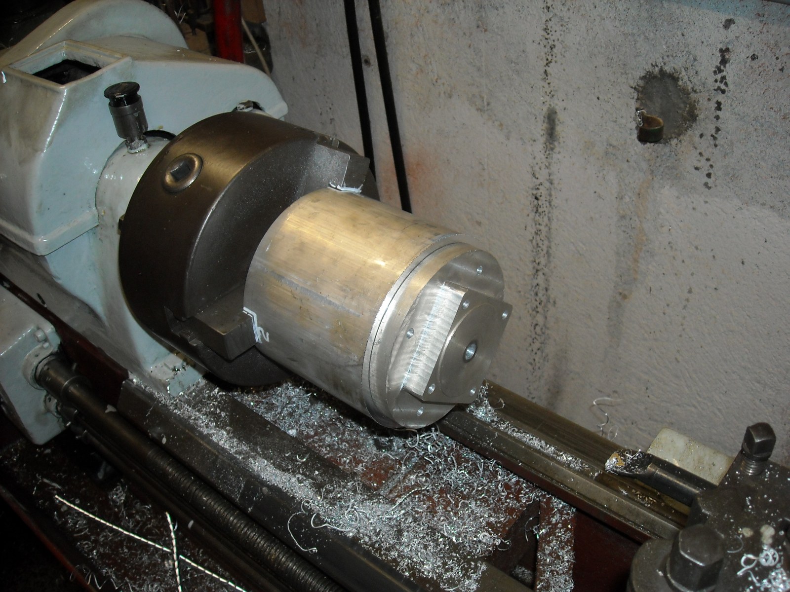
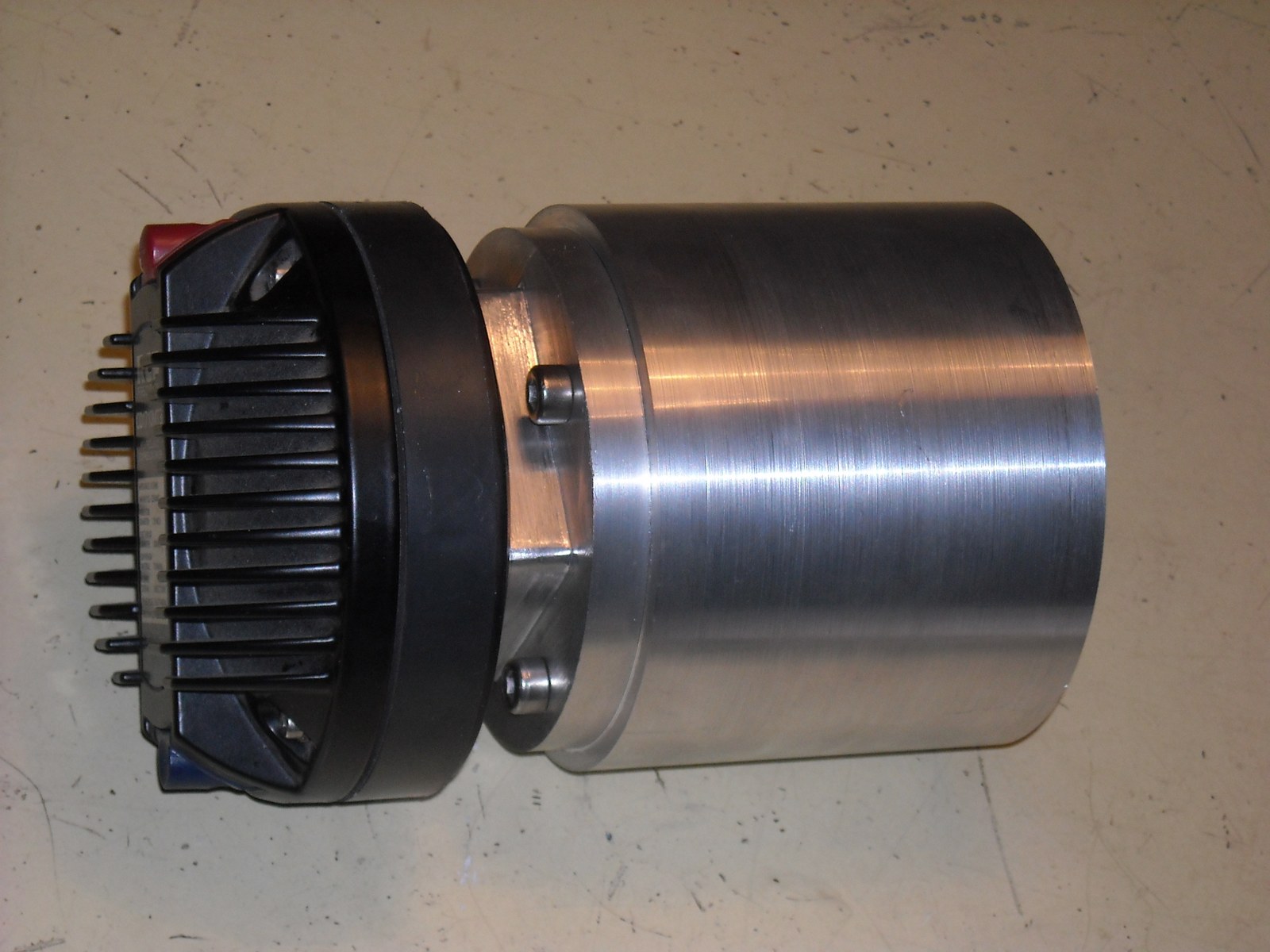
, and no additional chambers needed.
    i'm a self-taught, for sure I havnt the truth in my hand, the only thing i can do is reading, getting some formulas and making experiments

    at the moment the flange has only a 10mm hole for locking on the milling machine, i left 15mm dia, when i will be near to complete the horn i will add the flange and i will fillet the 2 parts together.

    the project in the first pic is old, i made i think 3 years ago. the profile is the same.
    The bad thing is that i'm learning to do things... i make one mistake after another


    Good advices for a newbie (threading tools lathe)-dscn0118_900x1200.jpg Good advices for a newbie (threading tools lathe)-dscn0120_1600x1200.jpg Good advices for a newbie (threading tools lathe)-dscn0122_1600x1200.jpg

    Good advices for a newbie (threading tools lathe)-dscn0123_1600x1200.jpgGood advices for a newbie (threading tools lathe)-dscn0124_1600x1200.jpgGood advices for a newbie (threading tools lathe)-dscn0126_1600x1200.jpg

    2000 Tool Plans

  4. The Following 3 Users Say Thank You to rendoman For This Useful Post:

    C-Bag (Jan 1, 2016), kbalch (Dec 31, 2015), PJs (Dec 31, 2015)

  5. #23
    Supporting Member rendoman's Avatar
    Join Date
    Nov 2015
    Location
    Italy
    Posts
    435
    Thanks
    451
    Thanked 496 Times in 241 Posts

    rendoman's Tools
    I think i need some new inserts... or have to learn to grind very sharp blade for alu...
    ... the part begins to take shape!

    Good advices for a newbie (threading tools lathe)-dscn0119_1600x1200.jpg Good advices for a newbie (threading tools lathe)-dscn0124_1600x1200.jpg Good advices for a newbie (threading tools lathe)-dscn0127_1600x1200.jpgGood advices for a newbie (threading tools lathe)-dscn0128_1600x1200.jpg Good advices for a newbie (threading tools lathe)-dscn0129_1600x1200.jpg Good advices for a newbie (threading tools lathe)-dscn0130_1600x1200.jpgGood advices for a newbie (threading tools lathe)-dscn0131_1600x1200.jpg Good advices for a newbie (threading tools lathe)-dscn0134_1600x1200.jpg Good advices for a newbie (threading tools lathe)-dscn0138_1600x1200.jpg

  6. The Following 3 Users Say Thank You to rendoman For This Useful Post:

    C-Bag (Jan 1, 2016), kbalch (Jan 2, 2016), PJs (Jan 1, 2016)

  7. #24
    PJs
    PJs is offline
    Supporting Member PJs's Avatar
    Join Date
    Sep 2014
    Location
    Northern CA
    Posts
    1,841
    Thanks
    8,337
    Thanked 1,118 Times in 718 Posts

    PJs's Tools
    Looking Real Good Stefano!! Pretty impressive lathe and horizontal mill you have. What are the models?

    Sorry I hadn't answered your previous post as I have been busy with some research on horn design. Found some interesting stuff out there. Better to keep my mouth shut when I was up to my ears in it!

    Martin King has some pretty impressive write ups with formulas and serious math, particularly on front loaded horn design and theory. There was more out there I found but this suited my liking for learning.

    From what I gleaned from his front loaded horn paper it seems to me the that the length of the 1" exit channel does have an impact on the frequency range and SPL...although I read it quickly and may have misinterpreted his meaning¿

    As for the fc it seems to me that it would be better to be just below the flat part of the curve...1.7k~2k maybe, to be able to keep just what you want. You could also add another filter at say12K to keep all the mids clean and within the capability of the driver. What made you choose the 7-800 range for fc?

    Thanks for sharing your build with us!! ~PJ
    ‘‘Always do right. This will gratify some people and astonish the rest.’’
    Mark Twain

  8. The Following 2 Users Say Thank You to PJs For This Useful Post:

    C-Bag (Jan 1, 2016), rendoman (Jan 3, 2016)

  9. #25
    Supporting Member C-Bag's Avatar
    Join Date
    Aug 2015
    Location
    California, central coast
    Posts
    720
    Thanks
    689
    Thanked 876 Times in 471 Posts

    C-Bag's Tools
    Interesting stuff.

    I would like to see details how the inner contour of the horn is done to match the print and to make them both the same. You guys have left me in the dust so I will continue from the peanut gallery.


  10. The Following 2 Users Say Thank You to C-Bag For This Useful Post:

    PJs (Jan 5, 2016), rendoman (Jan 3, 2016)

  11. #26
    Supporting Member rendoman's Avatar
    Join Date
    Nov 2015
    Location
    Italy
    Posts
    435
    Thanks
    451
    Thanked 496 Times in 241 Posts

    rendoman's Tools
    Hi
    The mill is a type zero of CST, it's a factory 30km away from my home town. I found some years ago a Kondia (Bridgeport style) but too heavy, the shipping was a disaster due to my narrow Street... I changed the water pump and the main engine, from 1hp dahlander 3phase 380 to 2hp 230v monophase and new bearings.

    The lathe i think is an old Grazioli fortuna (maybe 150 model), i say that because i see a close lathe with this name in the metal plate. No marks at all, outside and inside. I think it's a transition model between old lathe with leather belt and curvy leg base and "modern" trapezoidal belt. It's equipped with bronze brush, 3 gears main shaft and 4 gears for automatic ( longitudinal and transverse). 3cv- 2.2kw engine


    CST snc - ZERO

    CST snc - ZERO - caratteristiche

    i can't remember where i read to setup freq cutoff 100hz (from 100 to 200) lower the starting frequency of the speaker, one things i see is that the choice of cutoff can really make the difference in range. for exemple, the big horn of my speaker should have 80hz cutoff, this horn in my opinion can be used from 150hz and the upper limit is between 350 and 400hz , basically not only due to cutoff but to a coefficient that rules range and efficency.
    more the frequency, less the problems. up to 1000hz cutoff horns are tiny and "similar". imho problems are under 1000hz, for example my rcf driver with old 4\500hz cutoff sounded strange, not extendend, not focused, same material but smaller 800hz made great difference!

    I'm searching for an old site with a beautiful java tractrix and hyperbolic calculator, fullrange single driver site (maybe it changed name, maybe it doesn't exist anymore). good theory with formulas, exemple, tqwp, horn and project with lowther and a large number of drivers...
    i found this site, it's not like the original...

    Site Browser

    I have to search 2 pdf with a good calculation, maybe too specific and hard to read, but useful... i hope i'll find!

    ... and the inner contour... a big problem... i have to do by hand 
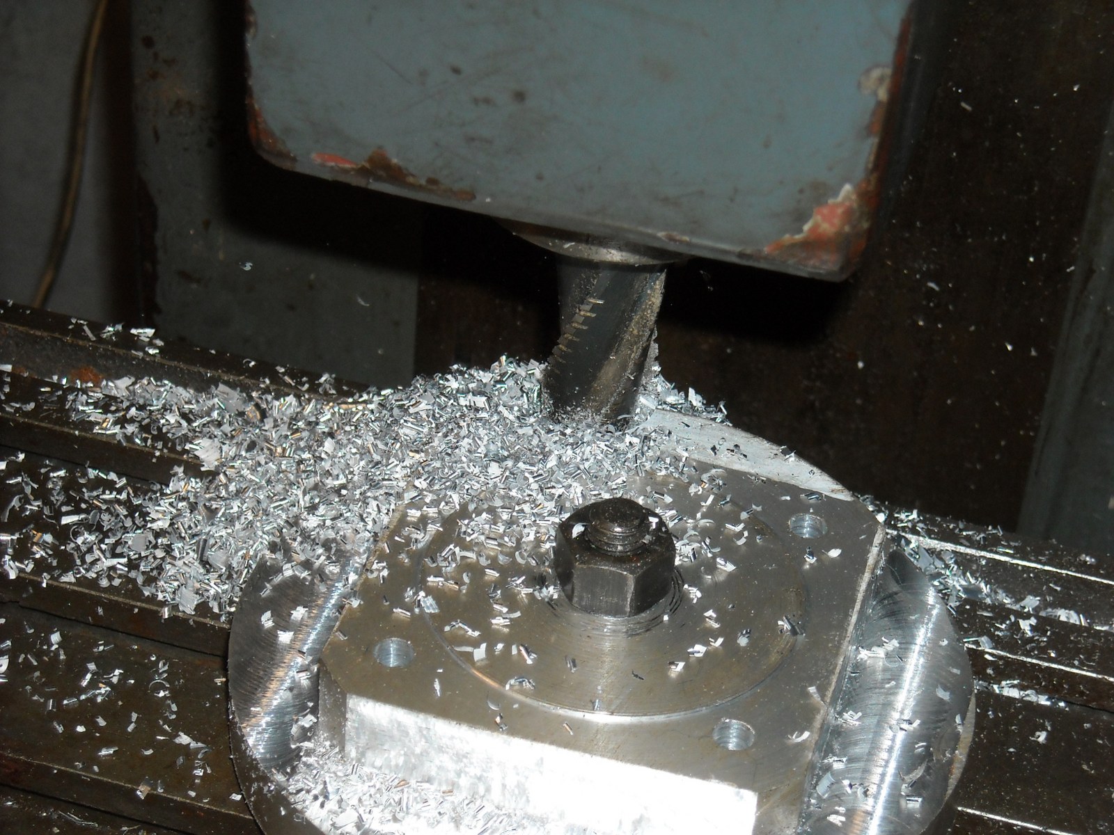
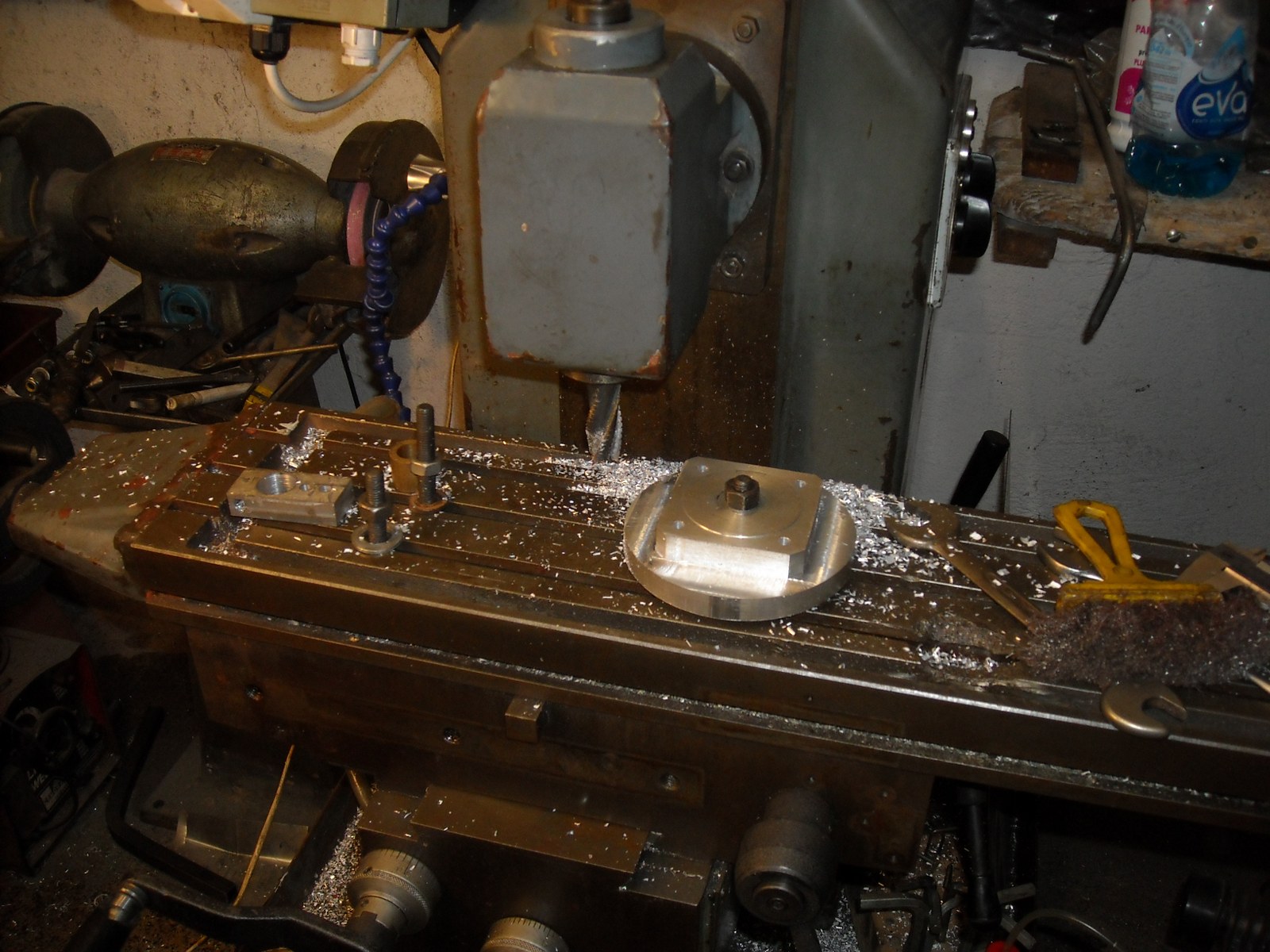
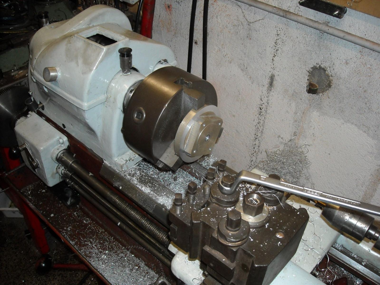
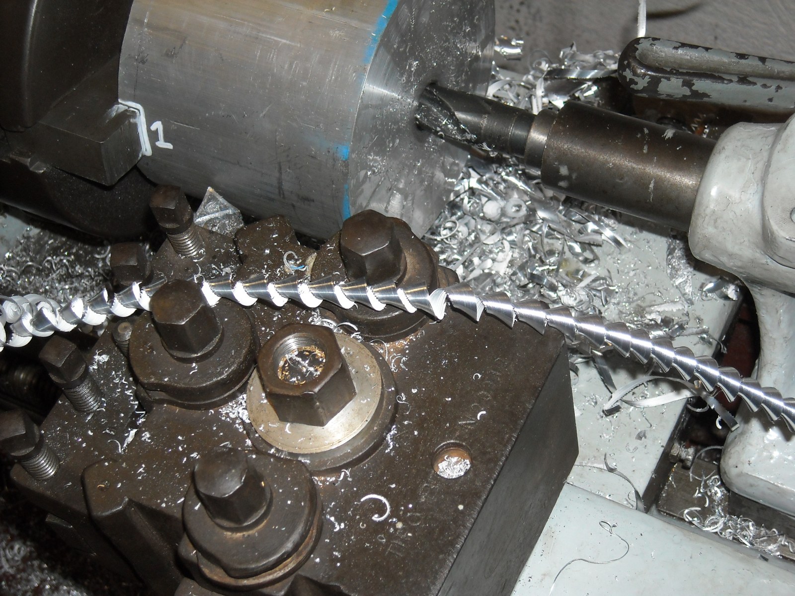
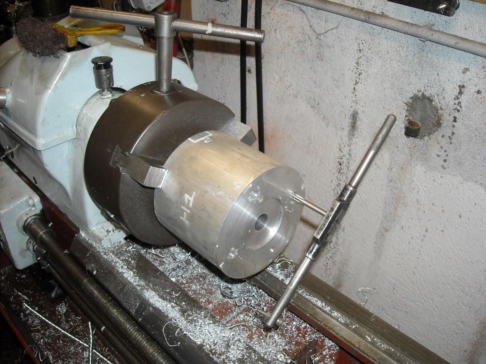
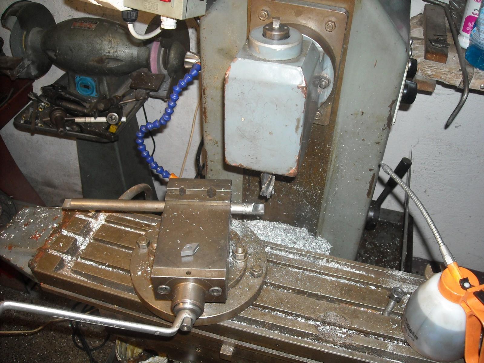
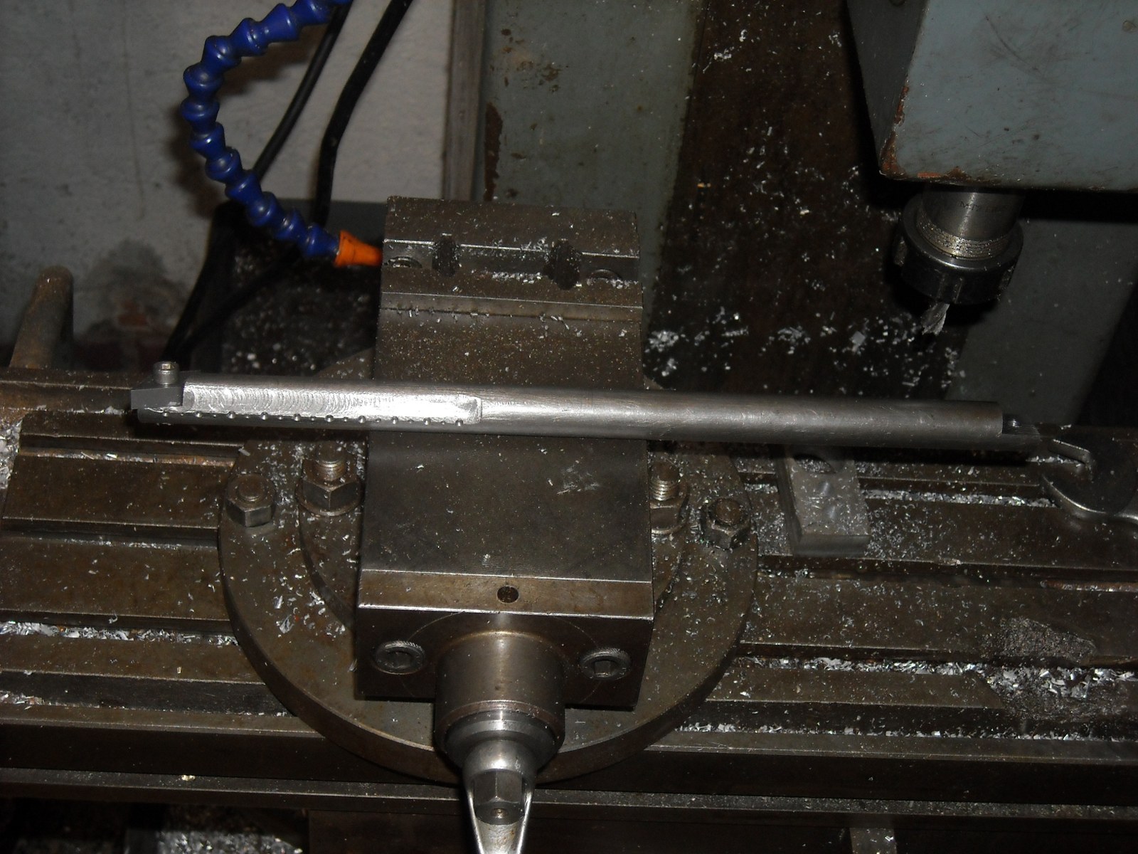
... a template Always near the cylinder, light movements, and i suppose as i did for the last small horn: rasp, file and huge sand paper work... and a lot of patience

  12. The Following User Says Thank You to rendoman For This Useful Post:

    PJs (Jan 3, 2016)

  13. #27
    Supporting Member rendoman's Avatar
    Join Date
    Nov 2015
    Location
    Italy
    Posts
    435
    Thanks
    451
    Thanked 496 Times in 241 Posts

    rendoman's Tools
    as usual i post the daily updates
    I tried building an internal tool, i got a good one Seco, but at the moment i have only one side of insert good and the tool is not long enough. I got some 100 of romboid inserts, i'm not sure i've done a good job, Tomorrow i will try on the horn cylinder.

    Got a question: i tried a blue ink for making marks on alu, but it makes a mess and it dissolves in few time. I saw in some youtube video (unfortunately i can't remember the link) a sort of purple glossy enamel, really thin that marks really well the metal, do you know the name of this special ink?

    I'm making cylindrical steps, then i will use the angle on turret for doing the profile, hope i will not have to use many sandpaper!

    Good advices for a newbie (threading tools lathe)-dscn0118_1600x1200.jpg Good advices for a newbie (threading tools lathe)-dscn0119_1600x1200.jpg Good advices for a newbie (threading tools lathe)-dscn0120_1600x1200.jpg

    Good advices for a newbie (threading tools lathe)-dscn0121_1600x1200.jpg Good advices for a newbie (threading tools lathe)-dscn0123_1600x1200.jpg Good advices for a newbie (threading tools lathe)-dscn0124_1600x1200.jpg

  14. The Following 2 Users Say Thank You to rendoman For This Useful Post:

    C-Bag (Jan 3, 2016), PJs (Jan 5, 2016)

  15. #28
    Supporting Member C-Bag's Avatar
    Join Date
    Aug 2015
    Location
    California, central coast
    Posts
    720
    Thanks
    689
    Thanked 876 Times in 471 Posts

    C-Bag's Tools
    Looking good.

    The stuff I've always used for layout is called Prussian Blue or Dykem steel blue. There's different types. The kind you want comes in a small plastic jar with a brush attached to the inside of the top. You brush it on and it dries really fast. If I understand what you are trying to do, I would use the Prussian Blue in one of the steps in the contour so you can use it like what I would call a witness line as you smooth horn to the final contour. That sounds like a LOT of work.

    These is also Prussian blue that a kind of blue grease that comes in a tube. It's wonderful for finding high and low spots in precision machining. I used it when I used to do valve jobs on the old air cooled VW's to check valve seat concentricity. And also scraping metal to achieve true flat surface. It's easy to tell where high and low spots are by how light or dark the blue is.

  16. The Following 3 Users Say Thank You to C-Bag For This Useful Post:

    Paul Jones (Mar 31, 2016), PJs (Jan 5, 2016), rendoman (Jan 4, 2016)

  17. #29
    PJs
    PJs is offline
    Supporting Member PJs's Avatar
    Join Date
    Sep 2014
    Location
    Northern CA
    Posts
    1,841
    Thanks
    8,337
    Thanked 1,118 Times in 718 Posts

    PJs's Tools
    Thanks for the info Stefano! Both mill and lathe look pretty substantial and good specs on the mill.

    I took a look at the "Site Browser" site and seemed pretty good. I found the last paragraph of the first link interesting.

    "For midrange and tweeter horns, many of the
    tractrix horn advantages are lost if the horn curve is terminated before the
    full, right-angle turn is reached. Unwanted edge diffractions would be created
    by the sharp edges of such a mouth. Thus no provision is made for the reduction
    of circular cross-section horns."

    The formulas there looked to be valid and could probably be done in Excel/spreadsheet, but it still comes back to that fc and in the case of a midrange the wavelength is very short (800hz = .0013) so I would assume it needs to be multiples instead of fractional...or just tiny. Assumptions have a way of biting me back though~ @¿@ ...Thoughts?

    The boring bar looks pretty good although those inserts don't seem to have a rake to them and may cause a bit of issue. Look forward to seeing how it works...think I might try it on something other than your part, first. ~¿@ Have you thought of maybe using a Graver to take off the tops of your steps? The depth may be a bit tricky to hold onto and need a rest to reach in there.
    Last edited by PJs; Jan 5, 2016 at 02:15 PM.
    ‘‘Always do right. This will gratify some people and astonish the rest.’’
    Mark Twain

  18. The Following User Says Thank You to PJs For This Useful Post:

    C-Bag (Jan 5, 2016)

  19. #30
    Supporting Member C-Bag's Avatar
    Join Date
    Aug 2015
    Location
    California, central coast
    Posts
    720
    Thanks
    689
    Thanked 876 Times in 471 Posts

    C-Bag's Tools
    Quote Originally Posted by PJs View Post
    "For midrange and tweeter horns, many of the
    tractrix horn advantages are lost if the horn curve is terminated before the
    full, right-angle turn is reached. Unwanted edge diffractions would be created
    by the sharp edges of such a mouth. Thus no provision is made for the reduction
    of circular cross-section horns."
    (way back at the back of the peanut gallery) So does this mean there's going to have to be a major redo in the outer edge of the horn?

Thread Information

Users Browsing this Thread

There are currently 1 users browsing this thread. (0 members and 1 guests)

Bookmarks

Posting Permissions

  • You may not post new threads
  • You may not post replies
  • You may not post attachments
  • You may not edit your posts
  •