
 LinkBack URL
 About LinkBacks

Hello all,
I have been reading this forum for some time to get inspiration for machining projects, and finally decided to share one of mine. I don't have much experience with machining, first time I have used a lathe was less than 6 months ago, so please don't judge too harshly. In this post I will share my process of making a hammer with replaceable faces and an elliptical multi-diameter handle.
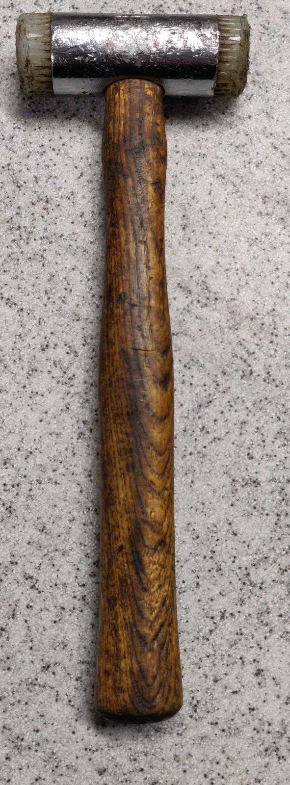
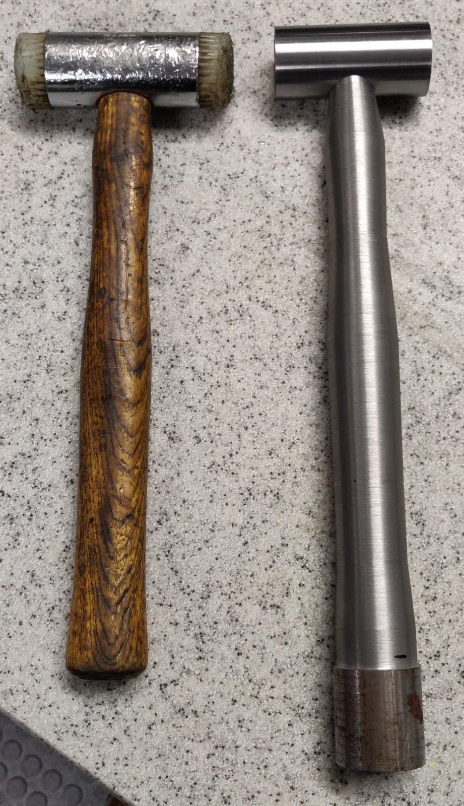
I have made the hammer head before deciding to share it, so I have no pictures of the process. However, the head is the easy part, it is just a 36 mm (1.4") diameter 60 mm (2.36") long cylinder with an M14 threaded hole through it and a 32 mm (1.25") diameter 3 mm (0.12") deep recess on both faces. I have been copying a hammer that a colleague of mine has, so I have used the same dimensions. The hammer looks like this:
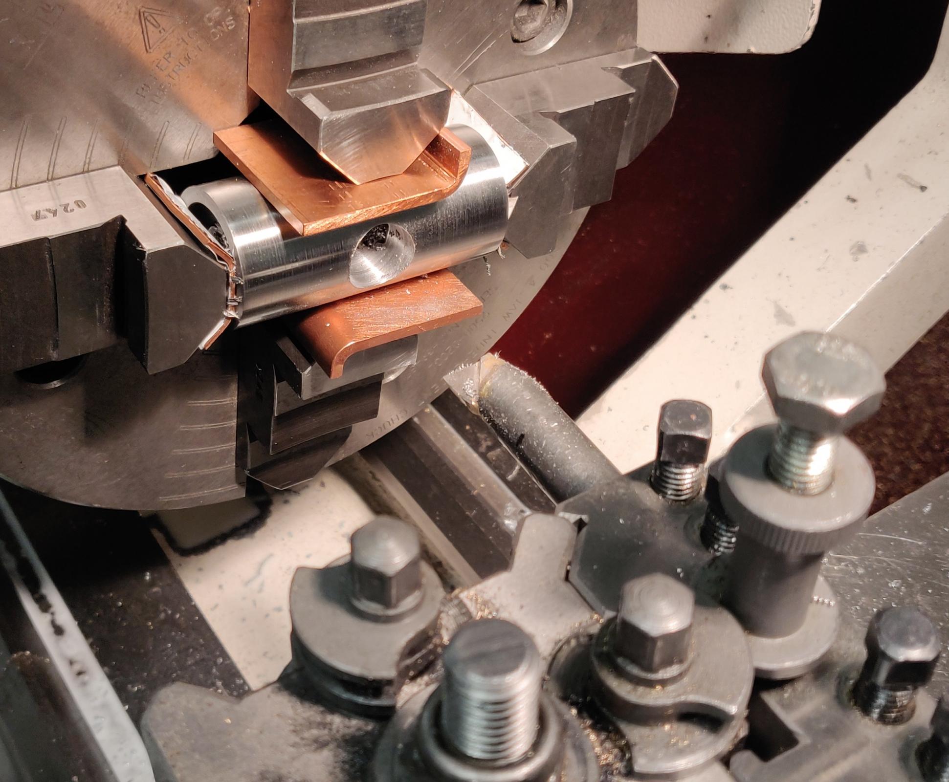
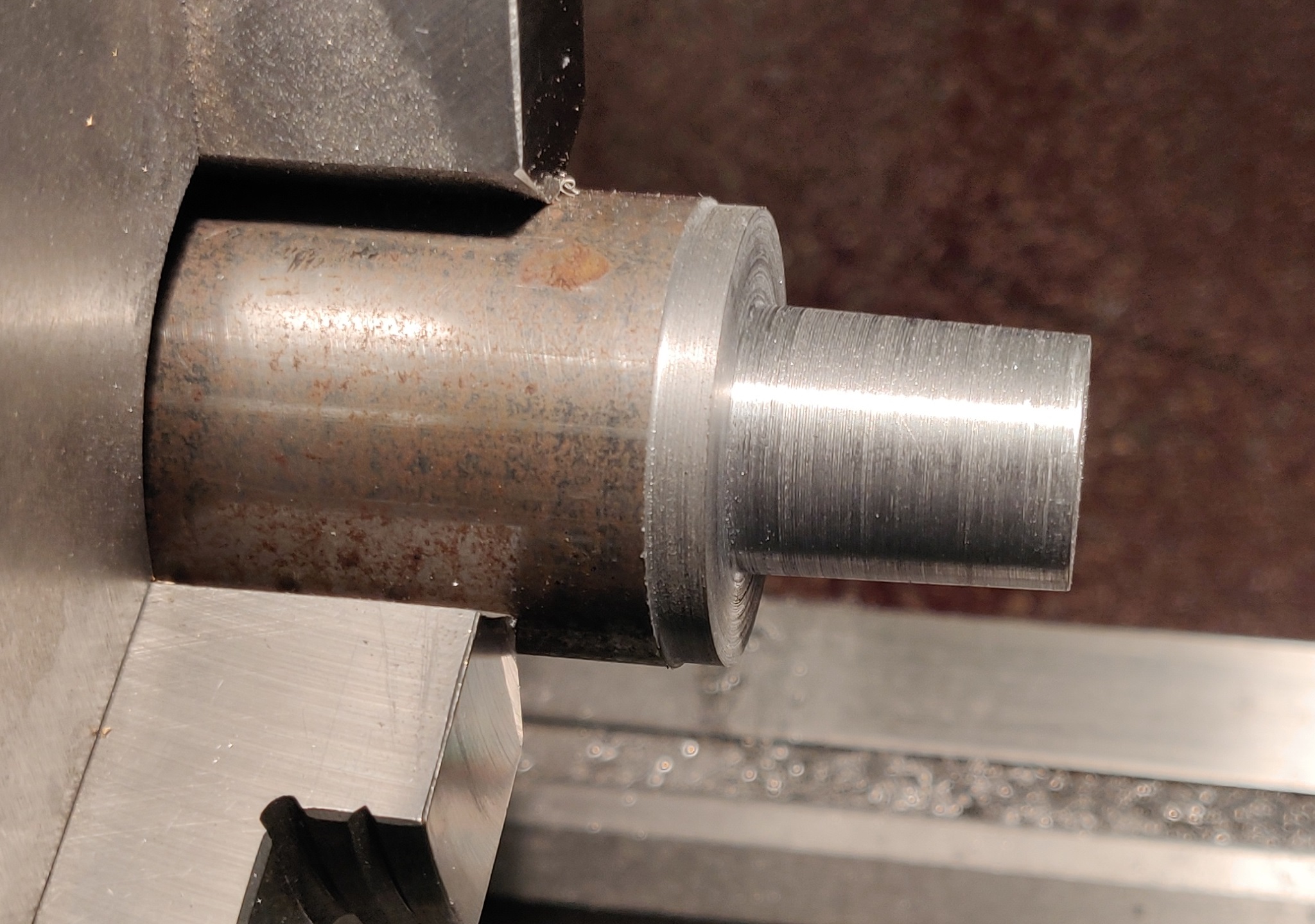
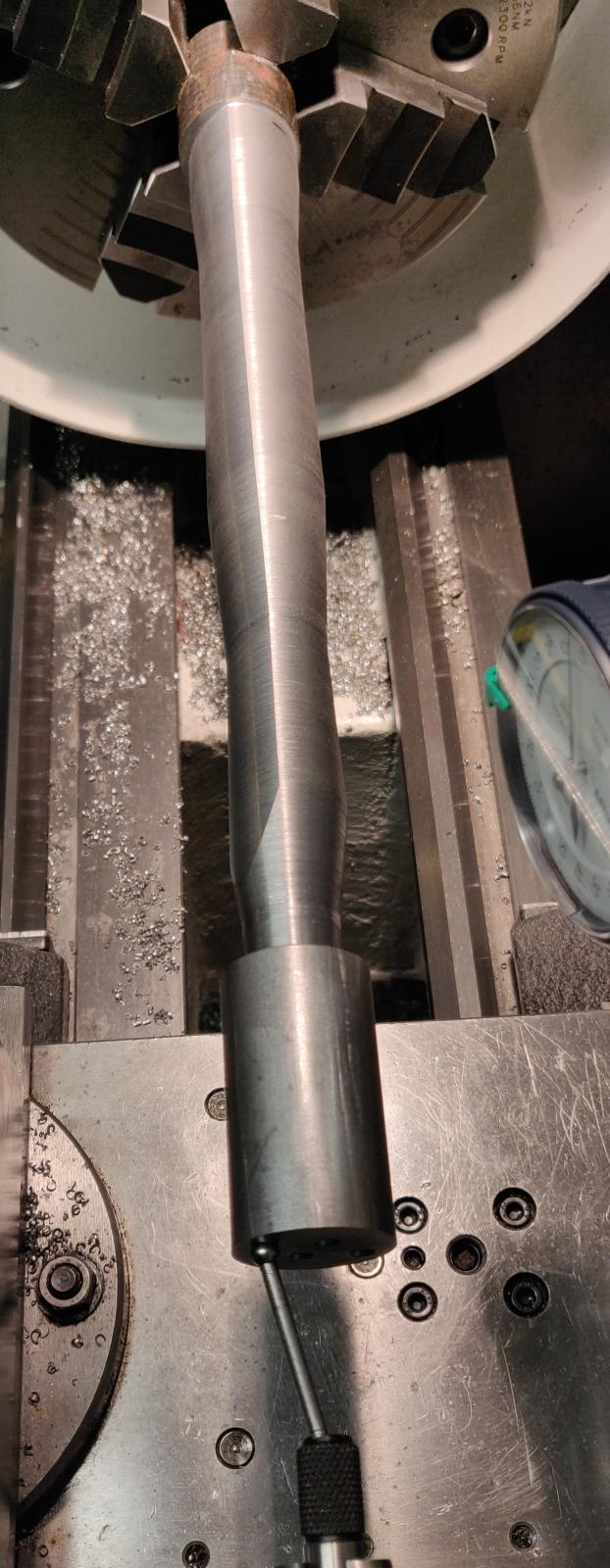
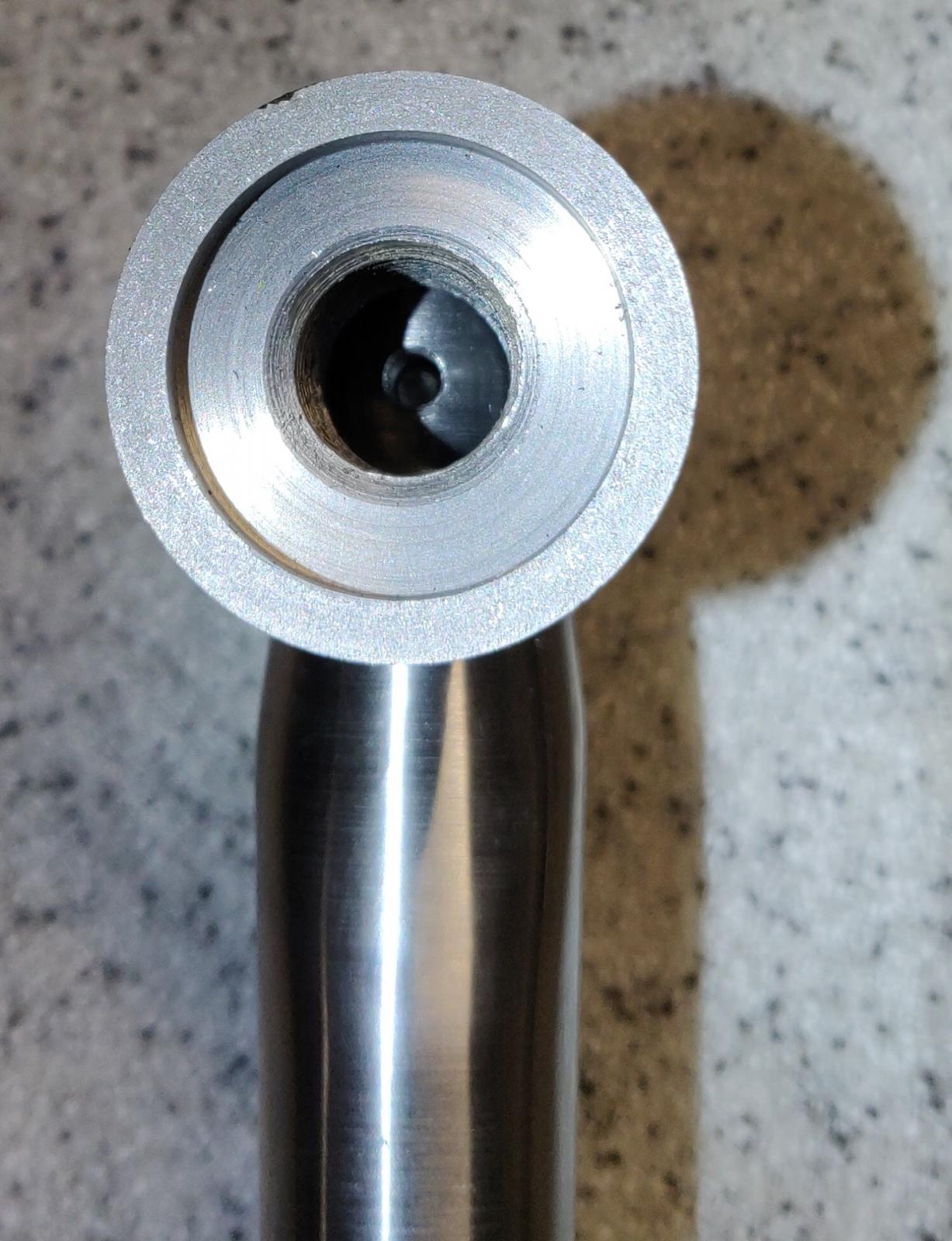
Once I have made the head (H13 tool steel), I needed a way to attach a handle to it. In order to do so I needed to make a hole in the centre of the head. It took some time to work out how the head will attach to the handle, at the end I have decided on a Morse taper style fixture as I didn't want the hole to go all the way through the head. At the time I was finishing the hammer head the mill was occupied (as I sadly don't have my own machines and have to share), so I had to get a 4 jaw chuck out, mount it on a lathe and mount the head in it. Once I was happy that the head was positioned true to the tailstock and the toolpost (after some magic with an indicator and the chuck key), I have drilled a centre hole that later was opened up to 16 mm (0.6"). This allowed me to use the smallest boring bar I have. I have then set the cross slide to 1.5 degrees (3 degrees total angle) to match a #3 Morse taper angle and made the first pass at the hole. It is at this stage when I have decided to start recording the process. Here is the hammer head with a tapered hole mounted in a 4 jaw chuck opened up to 20 mm (0.78") at the biggest end converging down to 18 mm (0.7") on the smallest end:
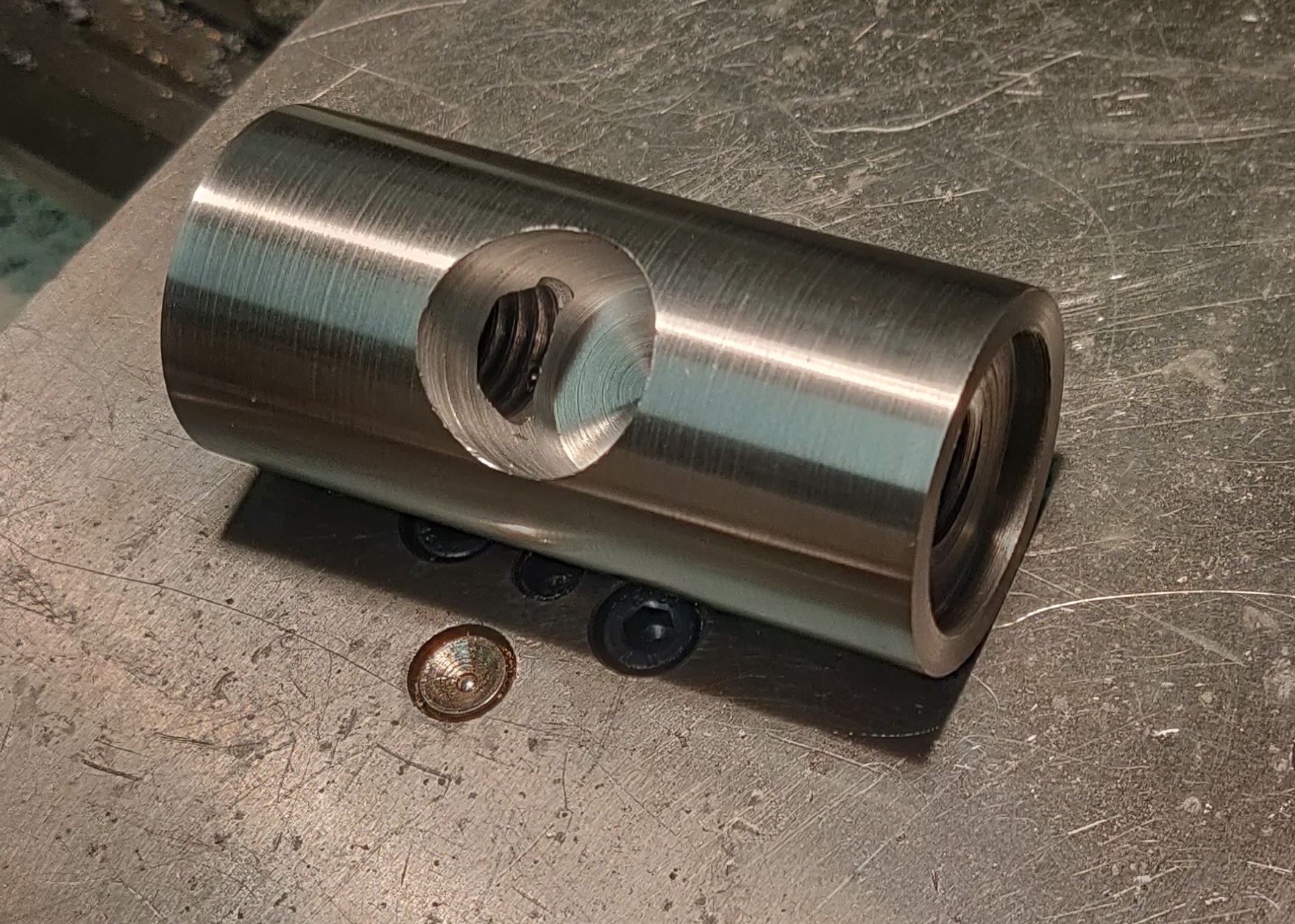
I've had already polished the hammer head prior to mounting it in a chuck, hence the copper inserts between it and the chuck jaws. Here is the finished hammer head:
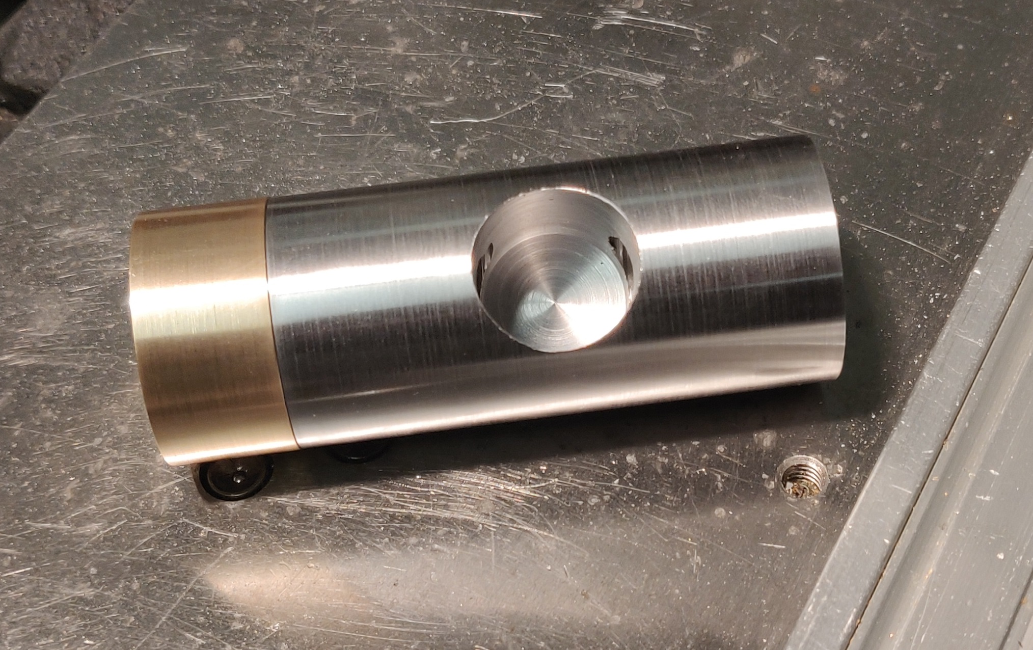
And the same head with a brass face attached to it:
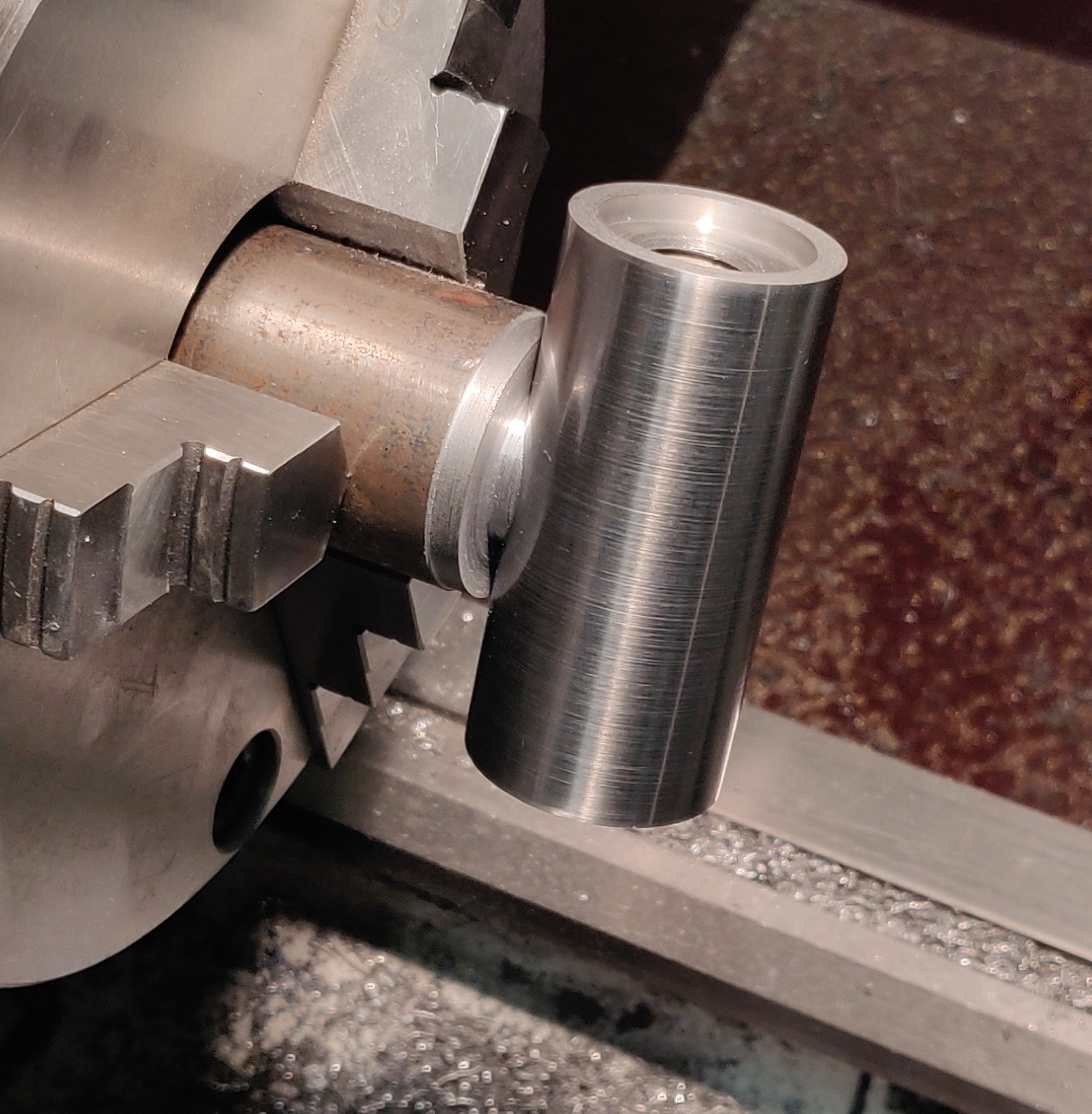
Then I went on to making the handle. First thing was to make a matching Morse taper stud which would fix the head in the correct position:
After some time I managed to get the taper length just right:
The head is locked in position and there are about 100 microns (4 thou) between it and the rest of the material.
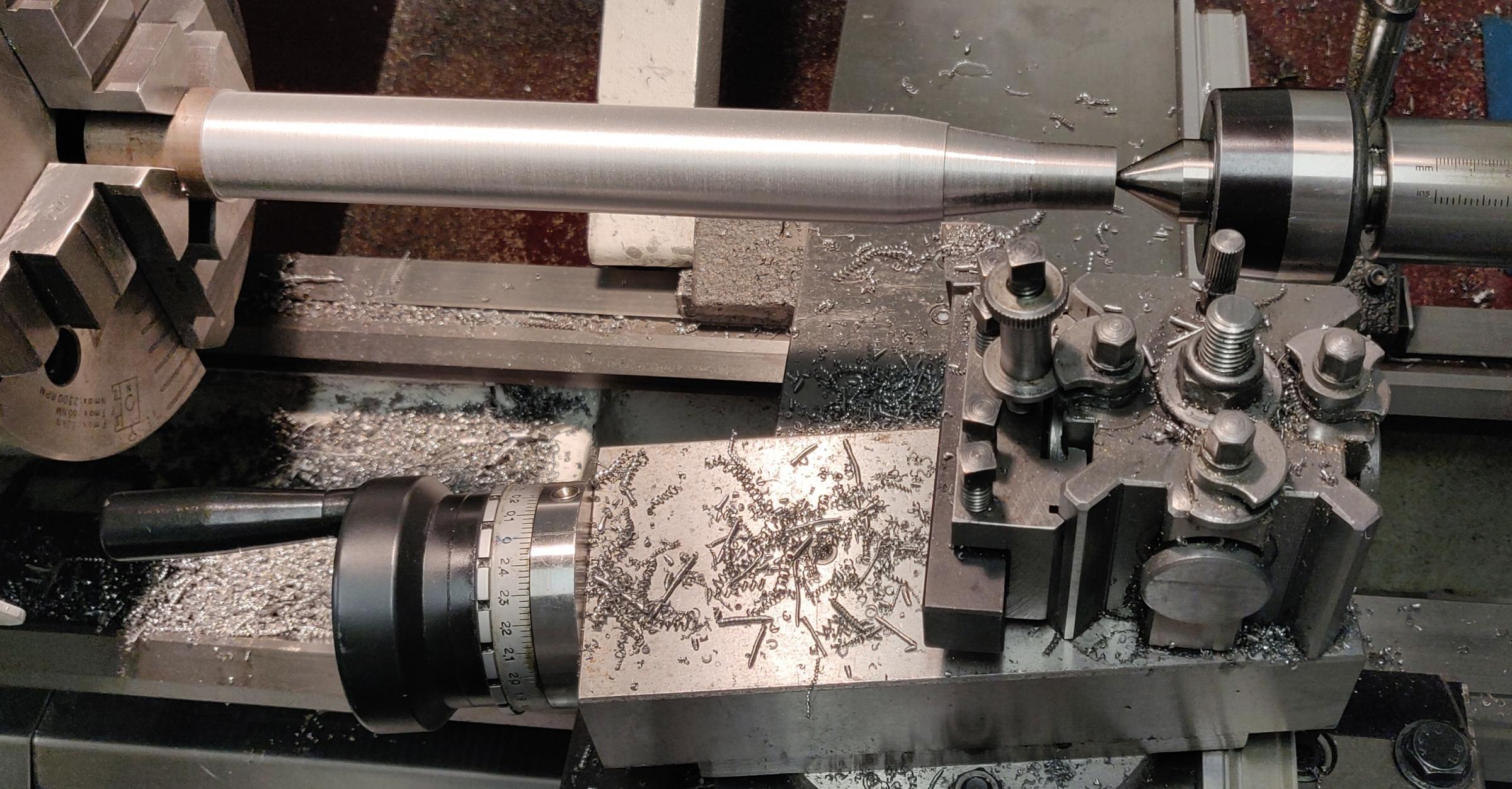
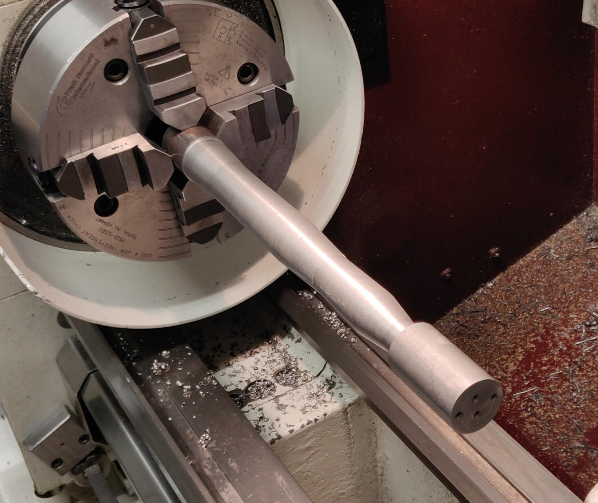
Once this was done, it was time to rough the largest handle diameter, which in this case was 30 mm (1.2"):
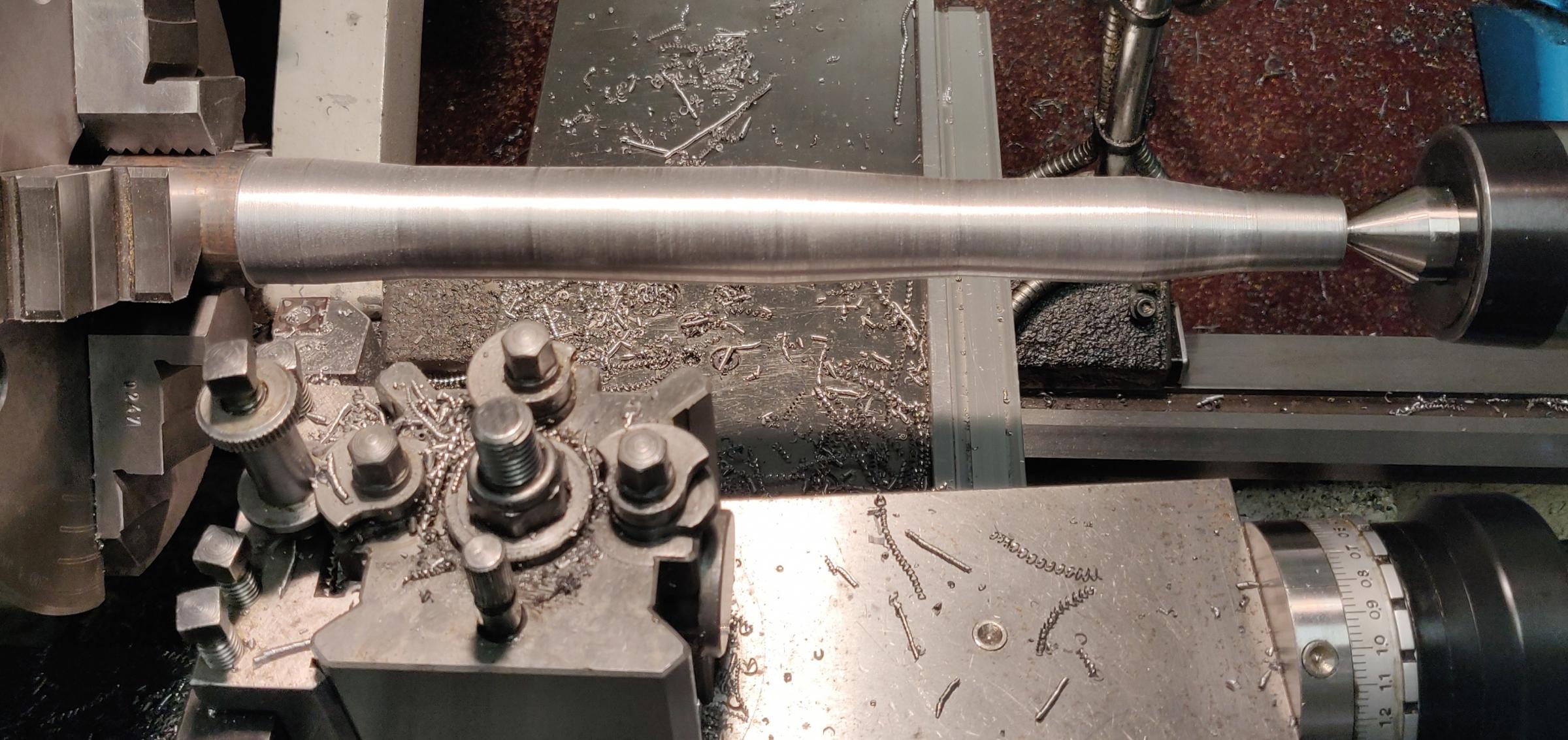
And after that finishing the rest of the sections:
Comparing the result to the original hammer:
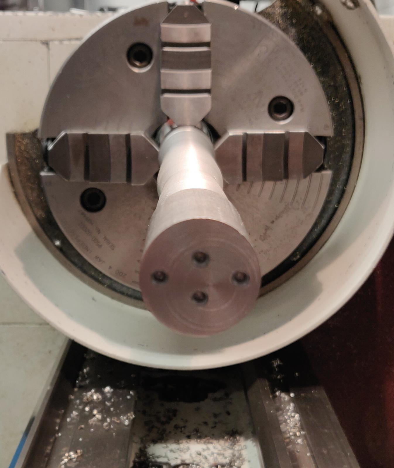
Now the hardest part: making an ellipse with multi-diameter sections. Making an ellipse on a lathe requires turning the part off centre and I have chosen to offset the part by 10 mm (0.4") from the centre. Drilling a centre hole in this case was impossible as the hole would have to be outside the end of the part, therefore I have made an attachment and drilled the off centre holes in it. I have made two sets of holes, 5 mm (0.2") and 10 mm (0.4") off centre just in case I change my mind during the process:
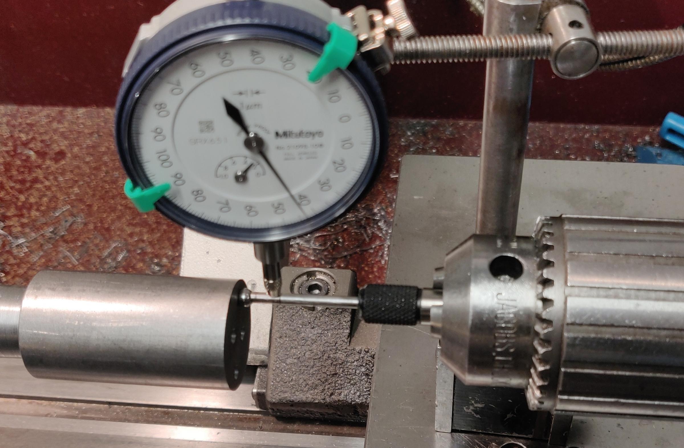
I did not want to turn the handle between centres, I have used the 4 jaw chuck to offset the part on one end and the centre holes on the other. I do not have an indicator with a 10 mm (0.4") travel, so I have used a centre finder mounted in the tailstock and a 1 mm (0.04") travel indicator to offset the 4 jaw chuck:
Start of the process of making an ellipse:
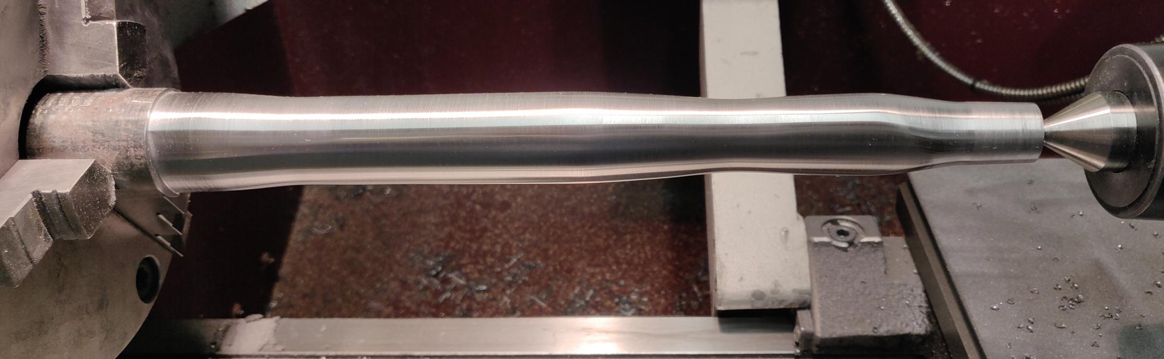
One side finished, preparing to offset to the other side:
Both sides finished and a light polish:
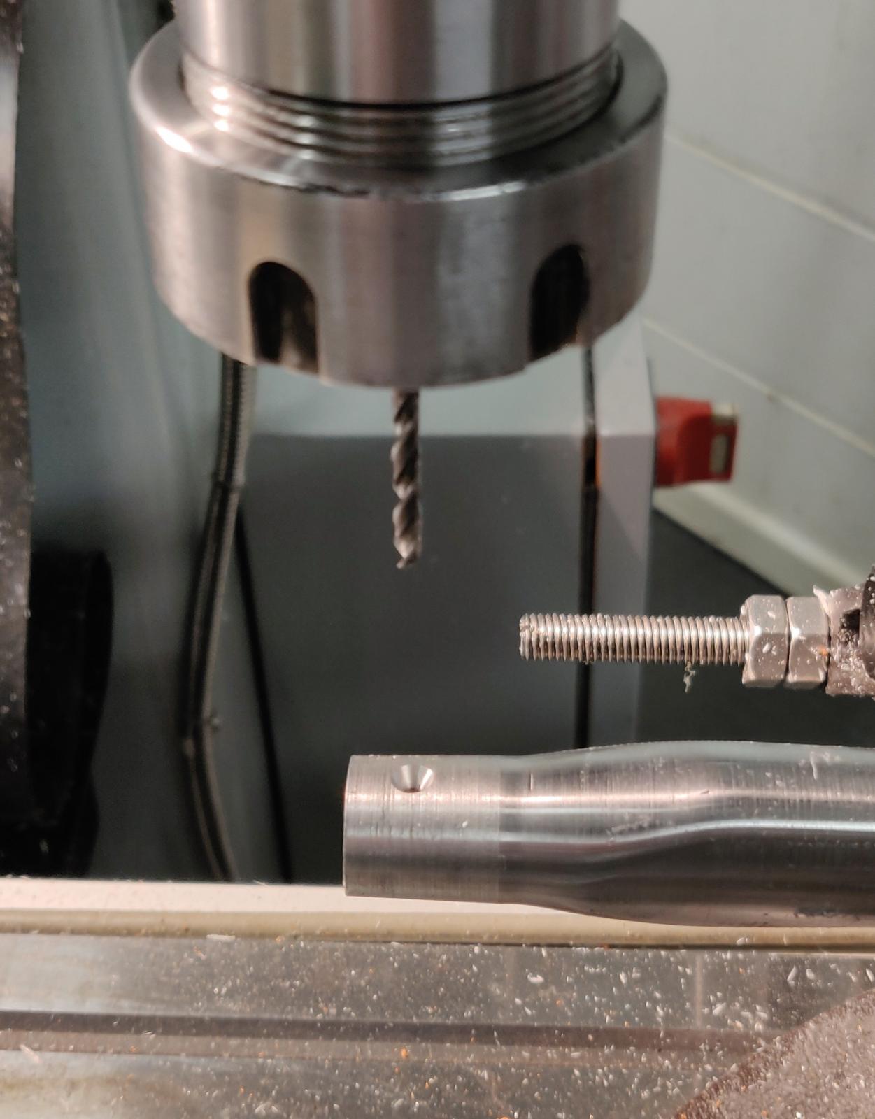
Now the problem of fixing the head to the handle needs to be solved. Morse taper is only good if all forces are in line with the handle. But this is a hammer, most of the forces will be from hitting things and they will be roughly perpendicular to the handle. In this situation the head and the handle will separate eventually (most likely after the first hit), which is potentially dangerous. So a way of making the head stick to the handle needs to be found. Since a Morse taper will hold the head in place as long as it does not rotate, something to counteract the forces attempting to separate the head and the handle is required. The head has a threaded hole all the way though it, so I have decided to utilise it and use some M3 screws to fix it to the handle. I have managed to get access to the mill for 30 minutes which was enough to drill and tap a hole through the middle of the Morse tapered end of the handle, which also would align with the centre of the M14 threaded hole in the head once fully inserted into it:
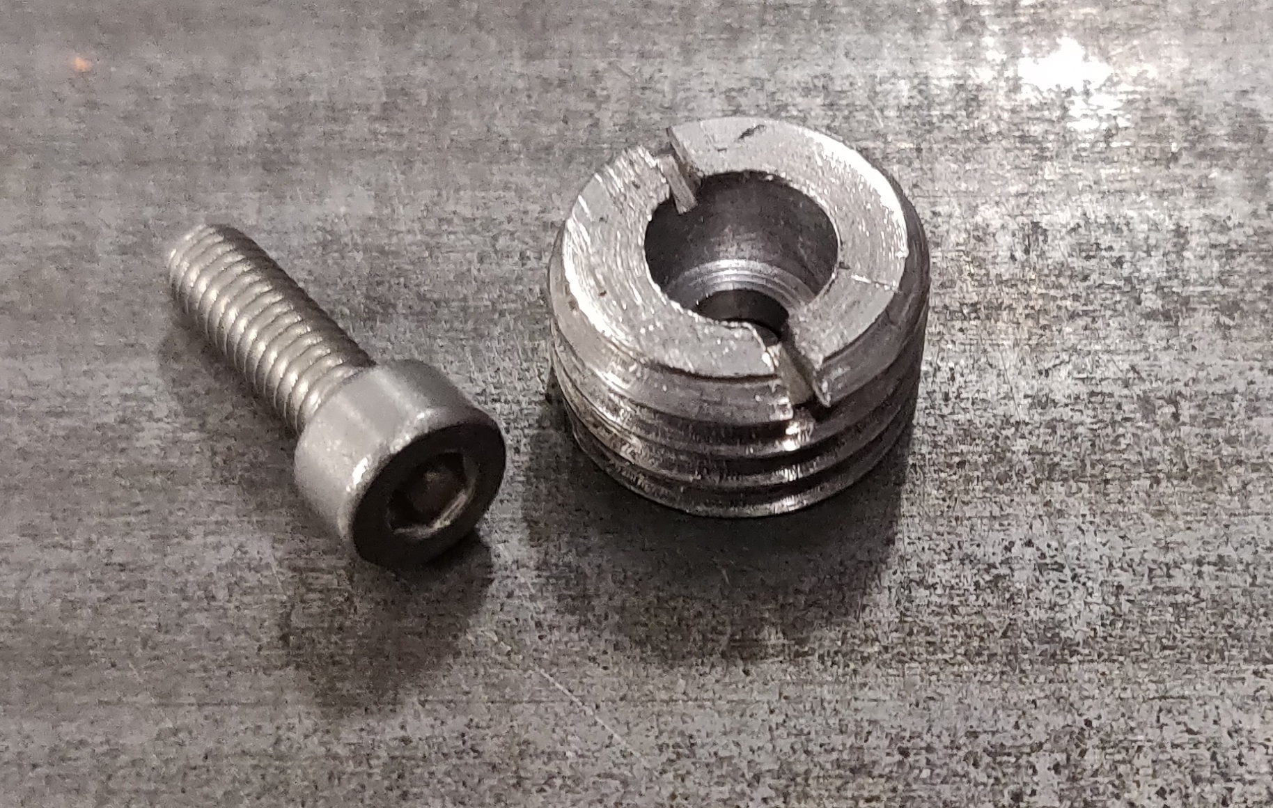
The thread, and consequently the hole in the head are too big for any M3 screw, so I have made two inserts with an M14 thread on the outside (to match the thread on the hammer head) 6 mm (0.24") long, 3.2 mm (0.125") diameter through hole and 7 mm (0.275") diameter 4 mm (0.157") deep recess to accept a standard M3 screw with a hex socket. I have also used a saw and made a cut for a flat head screwdriver in the insert:
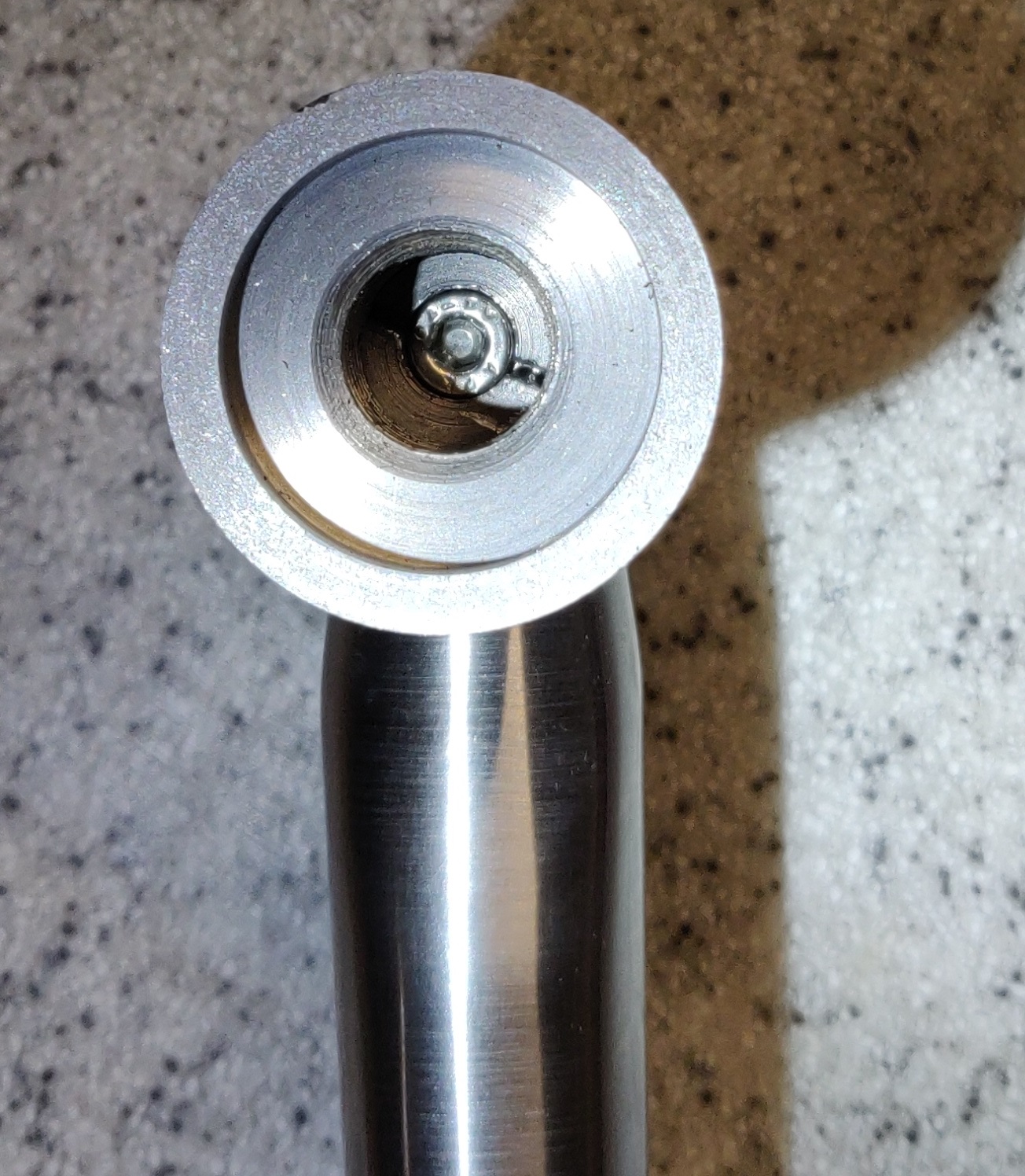
The idea was that once the tapered section of the thread is inserted into the head, the insert would screw into the hammer head tight against the handle and the M3 screw would be screwed into the handle using the insert as an anti-rotation fixture. Here is the picture of one side of the hammer head with the handle inserted into it before and after the insert and the screw were used:
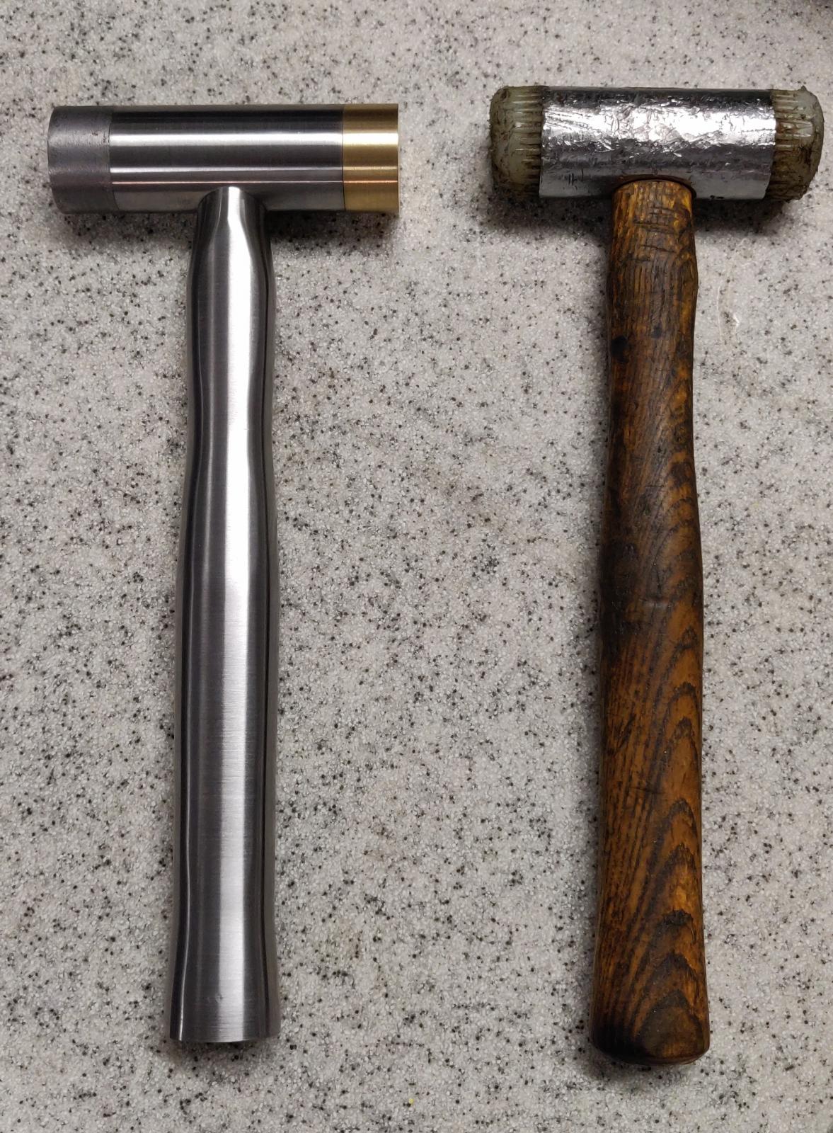
There are two inserts and screws, one from each side of the head (under each hammer face). I have not used this hammer to hit anything yet, so I can't comment on how well this system worked. In theory it should stop the handle from rotating inside the head thus preventing it from detaching from the head. I am yet to verify this in practice. Here is the picture of the finished hammer together with the one I was copying:
The faces on the original hammer are Nylon, on the one I've made they are brass and lead. I am in the process of making new faces from other materials such as Nylon, copper, wood and steel. Both the hammer head and the handle are made from H13 tool steel, the handle is solid. Because of this the hammer is on the heavy side, by my estimation about 1.3 kg (2.9 lbs). Despite the weight it is quite nice to hold in the hand, especially when the metal has warmed up a bit. The M3 screw is chrome plated stainless steel (I think), and the inserts are made from cold rolled steel.
If you do have any comments/suggestions/questions please leave them in the comments to this thread, I will respond/answer them as soon as I can.


 Reply With Quote


Bookmarks