Free 186 More Best Homemade Tools eBook:  
Get 2,000+ tool plans, full site access, and more.

User Tag List

Results 1 to 8 of 8

Thread: Laser Compound-Slide Angle Setting

  1. #1
    Supporting Member Christophe Mineau's Avatar
    Join Date
    Jul 2014
    Location
    France, Brittany !
    Posts
    913
    Thanks
    826
    Thanked 1,691 Times in 481 Posts

    Christophe Mineau's Tools

    Laser Compound-Slide Angle Setting

    Note : Jon, could you change the title please ? : "Laser Compound-Slide Angle Setting", thx !

    It's been a while I had in my drawer this little magnetic level, with a laser pointer.
    While finding the gadget quite funny I didn't know exactly what to do with it, and I think I have found the good use for it :

    It can be used as a laser pointer to precisely set up the angle of the compound slide of the lathe.
    In my shop, just at the right hand of my lathe, I happen to have an old cabinet wall. I discovered I could use it as a kind of ruler to precisely mark some remarkable angles of my compound slide, if I simply attach the magnetic laser level to the side of the slide, and if I put my apron and cross slide at a reference location.

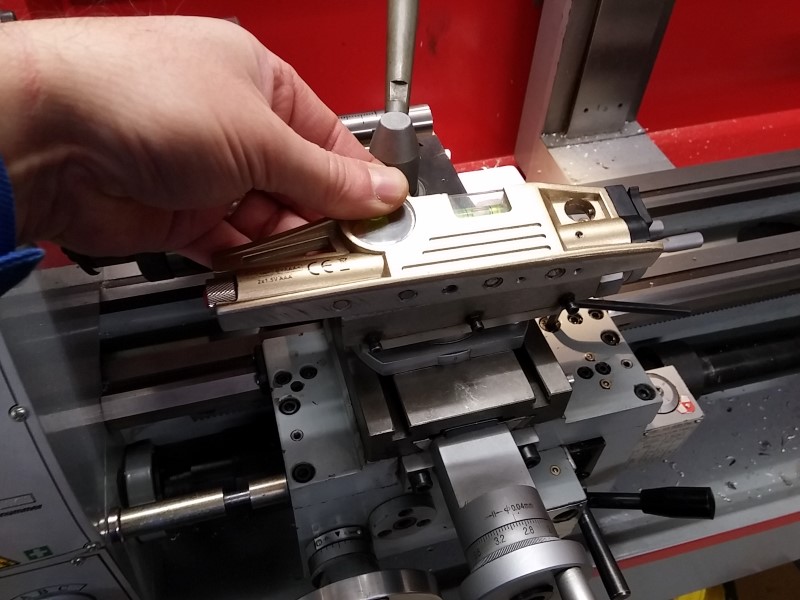
    Here is the laser level with its magnetic base :


    And here is where I install it : aligned just above the screw for setting up the gibs.
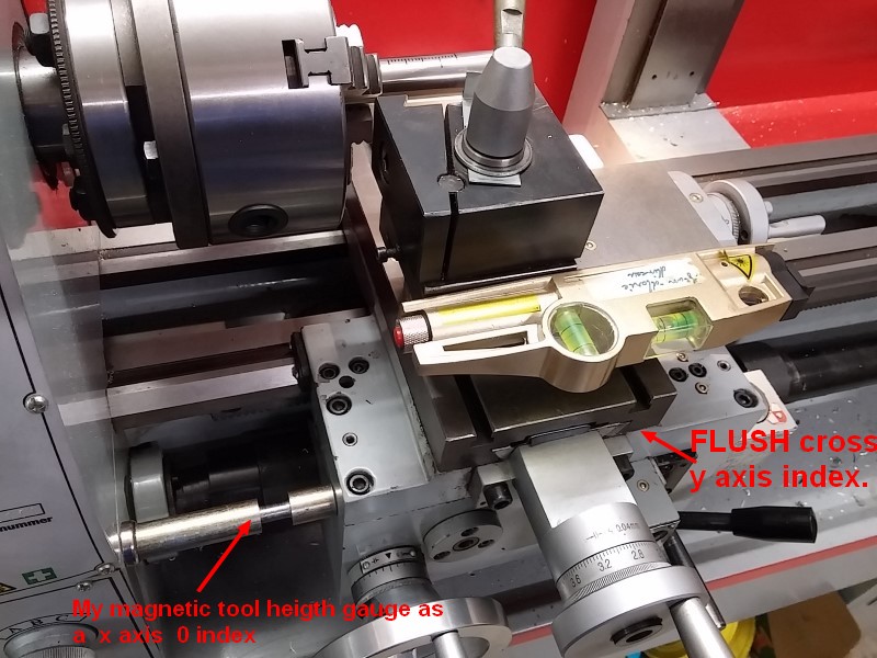
    As a convention, I set up my reference location like so :
    - For the Z axis, I stick my magnetic tool height gauge (see previous post) on the the side of the lathe head and use it as a stop for the apron.
    - For the X axis, I set up my cross slide so that the table is just flush to the apron (see the red arrows on the picture).

    (In above pic, please read Z instead of X and X instead of Y)

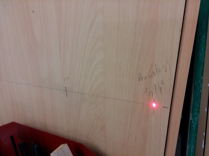
    Here you can see the beam on the wall of my cabinet. Notice that the farthest the wall would be, the more precise the reference would be.


    So I set up my compound angle to zero degree using a dial and thus I could mark on the wall the exact zero degree position.
    Having measured the distance from the wall and the axis of the compound, I can then calculate and mark any remarkable angle I would like to quickly set up.
    Offset = distance x tan(alpha)
    Here for example I marked the famous 5.74°, which correspond to Arcsin(0.1), see this great post from tonyfoal


    Of course, if I need wider angles, I could screw, maybe with an hinge to be able to fold it back, a kind of ruler extension to the wall of my cabinet.

    186 More Best Homemade Tools eBook
    Last edited by Christophe Mineau; Mar 22, 2017 at 06:48 AM. Reason: oups!! Changed X and Y axis by Z and X, thanks tonyfoal
    Cheers !
    Christophe
    ________________________________________________________________
    Visit my Website : http://www.labellenote.fr/
    Facebook : La Belle Note
    All my personal works, unless explicitly specified, are released under
    Creative Commons BY-NC-SA license.

  2. The Following 4 Users Say Thank You to Christophe Mineau For This Useful Post:

    mr95gst (Mar 21, 2017), olderdan (Mar 21, 2017), Paul Jones (Mar 21, 2017), Seedtick (Mar 21, 2017)

  3. #2
    Content Editor
    Supporting Member
    DIYer's Avatar
    Join Date
    Aug 2013
    Posts
    3,056
    Thanks
    772
    Thanked 1,852 Times in 1,653 Posts


    Thanks Christophe Mineau! We've added your Compound Slide Angle Setting Tool to our Measuring and Marking category,
    as well as to your builder page: Christophe Mineau's Homemade Tools. Your receipt:


    2000 Tool Plans

  4. The Following User Says Thank You to DIYer For This Useful Post:

    mklotz (Mar 21, 2017)

  5. #3
    Supporting Member mklotz's Avatar
    Join Date
    Aug 2015
    Location
    LA, CA, USA
    Posts
    3,436
    Thanks
    357
    Thanked 6,391 Times in 2,118 Posts

    mklotz's Tools
    Establishing the null y-axis position by setting the cross-slide flush with the apron seems like it might be a bit difficult to reproduce accurately. Even a small error will cause your scale on the cabinet to have a translation error.

    A more reproducible way to set the null would be to first mount the laser to the front edge of the cross-slide and adjust the cross-slide until the beam points to a reference mark on the cabinet. This would assure that the cross-slide is always in the same null location. Then proceed as you described to adjust the angle of the compound.

    BTW, your lathe is insanely clean. If my lathe looked like that, I'd be afraid to touch it lest the fingerprints show. I'm thinking you have one of those lovely French maids come in to tidy up after every shop session. (Just joking, Christophe. I'm really envious of your tidiness.)
    ---
    Regards, Marv

    Home Shop Freeware
    https://www.myvirtualnetwork.com/mklotz

  6. The Following User Says Thank You to mklotz For This Useful Post:

    Christophe Mineau (Mar 21, 2017)

  7. #4
    Supporting Member tonyfoale's Avatar
    Join Date
    Nov 2016
    Location
    Spain
    Posts
    1,556
    Thanks
    686
    Thanked 2,643 Times in 708 Posts

    tonyfoale's Tools
    Quote Originally Posted by mklotz View Post
    Establishing the null y-axis position by setting the cross-slide flush with the apron seems like it might be a bit difficult to reproduce accurately. Even a small error will cause your scale on the cabinet to have a translation error.
    Marv,

    I think that you are making a mountain out of a mole hill.
    Just by feel you could repeat that setting probably to less than 0.1mm, definitely 0.2mm maximum. The translation error on the board would be the same as that error and compared to the ability to repeat the dot position on the drawn line it would be trivial.
    If you held a small flat block against the saddle edge you could probably set the cross slide position to better than 0.05mm in seconds. Ones ability to set the cross slide position as per Christophe's method far exceeds ones ability to detect a tiny error between the laser dot and the drawn line. I fear that your method would be an order of magnitude less repeatable.

    Christophe et al,

    it is a convention that the spindle axis of a machine tool is designated as Z. On a lathe what you have called the X axis should be termed Z and your Y is generally called X. Personally I don't like it but that is the convention and less misunderstandings occur if we all use the same notation.

  8. The Following 2 Users Say Thank You to tonyfoale For This Useful Post:

    Christophe Mineau (Mar 21, 2017), olderdan (Mar 21, 2017)

  9. #5
    Supporting Member
    Join Date
    May 2013
    Posts
    40
    Thanks
    61
    Thanked 7 Times in 7 Posts
    Christophe,

    Beautiful! That is one clever procedure! Now I gotta get one of them special levels and set one up myself!

    ---Joe

  10. The Following User Says Thank You to j.bickley For This Useful Post:

    Christophe Mineau (Mar 21, 2017)

  11. #6
    Supporting Member Christophe Mineau's Avatar
    Join Date
    Jul 2014
    Location
    France, Brittany !
    Posts
    913
    Thanks
    826
    Thanked 1,691 Times in 481 Posts

    Christophe Mineau's Tools
    Hi Marv, thanks for the comment
    Quote Originally Posted by mklotz View Post
    A more reproducible way to set the null would be to first mount the laser to the front edge of the cross-slide and adjust the cross-slide until the beam points to a reference mark on the cabinet. This would assure that the cross-slide is always in the same null location. Then proceed as you described to adjust the angle of the compound.
    That's true, but honestly doesn't make mush difference as said tonyfoal. The beam at that distance is ~1 cm wide. Anyway, it's easy to point the center of the beam.


    Quote Originally Posted by mklotz View Post
    BTW, your lathe is insanely clean. If my lathe looked like that, I'd be afraid to touch it lest the fingerprints show. I'm thinking you have one of those lovely French maids come in to tidy up after every shop session. (Just joking, Christophe. I'm really envious of your tidiness.)
    Yes ! But actually I did a full cleanup just before that, after plenty of turning of milling
    Cheers !
    Christophe
    ________________________________________________________________
    Visit my Website : http://www.labellenote.fr/
    Facebook : La Belle Note
    All my personal works, unless explicitly specified, are released under
    Creative Commons BY-NC-SA license.

  12. #7
    Supporting Member Christophe Mineau's Avatar
    Join Date
    Jul 2014
    Location
    France, Brittany !
    Posts
    913
    Thanks
    826
    Thanked 1,691 Times in 481 Posts

    Christophe Mineau's Tools
    Quote Originally Posted by tonyfoale View Post
    it is a convention that the spindle axis of a machine tool is designated as Z. On a lathe what you have called the X axis should be termed Z and your Y is generally called X. Personally I don't like it but that is the convention and less misunderstandings occur if we all use the same notation.
    Thanks Tony for the comment, I learned something, and I changed in the post.
    But actually (even if this not why I made this mistake, I must admit), I have a milling head now on this lathe, so for the mill, the Z would really be vertical !
    Cheers !
    Christophe
    ________________________________________________________________
    Visit my Website : http://www.labellenote.fr/
    Facebook : La Belle Note
    All my personal works, unless explicitly specified, are released under
    Creative Commons BY-NC-SA license.

  13. #8
    Supporting Member tonyfoale's Avatar
    Join Date
    Nov 2016
    Location
    Spain
    Posts
    1,556
    Thanks
    686
    Thanked 2,643 Times in 708 Posts

    tonyfoale's Tools
    Quote Originally Posted by Christophe Mineau View Post
    Thanks Tony for the comment, I learned something, and I changed in the post.
    But actually (even if this not why I made this mistake, I must admit), I have a milling head now on this lathe, so for the mill, the Z would really be vertical !
    Christophe,

    Of course you are right, the convention falls down when you have multiple spindles. I do not know how you decide which axis has the priority. There is probably a rule but I don't know it. Basically, prior to NC and later CNC, nobody thought in terms of Cartesian coordinates for machining, but CNC has changed all that and I guess that the conventions were laid down before the advent of multi-spindle machines.

    BTW I have exactly the same type of laser level as yours which I use for numerous alignment purposes but none the same as you. There is a focus adjustment on it and I think that if you play with that you might get a smaller dot, 10mm is way bigger than it could be. At the distance that you are talking about I can get a dot no more than 2mm diameter.


    186 More Best Homemade Tools eBook

Thread Information

Users Browsing this Thread

There are currently 1 users browsing this thread. (0 members and 1 guests)

Bookmarks

Posting Permissions

  • You may not post new threads
  • You may not post replies
  • You may not post attachments
  • You may not edit your posts
  •