Free 186 More Best Homemade Tools eBook:  
Get 2,000+ tool plans, full site access, and more.

User Tag List

Page 2 of 3 FirstFirst 1 2 3 LastLast
Results 11 to 20 of 30

Thread: Lathe restoration SN20

  1. #11
    Supporting Member NortonDommi's Avatar
    Join Date
    Jul 2014
    Location
    North Island, New Zealand.
    Posts
    990
    Thanks
    1,800
    Thanked 525 Times in 315 Posts

    NortonDommi's Tools
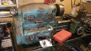
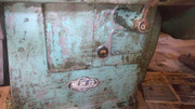
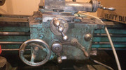
    That's very interesting. As said I'd never even heard of anything like this before, I suppose it could have been set up for turning standard tapers much quicker than a taper attachment. Was a pretty sizeable machine though, wouldn't have fitted in my shed : P From memory it could also cut just about every thread in existence and I suspect you needed a special license to operate.

    186 More Best Homemade Tools eBook

  2. #12
    Supporting Member thehomeengineer's Avatar
    Join Date
    Nov 2017
    Location
    Berkshire UK
    Posts
    706
    Thanks
    722
    Thanked 2,069 Times in 407 Posts

    thehomeengineer's Tools
    Hi
    I had a TOS lathe wish I never sold it but needed the money as I was buying a house. The clutch went on the lathe and in the UK the 600 Group offer spares for TOS lathes.600 Group PLC - manufacturer and distributor of machine tools, laser marking systems, precision engineered components and mechanical handling & waste management equipment The spares were expensive so had the bits need for the clutch lazer cut.

    2000 Tool Plans

  3. #13
    Supporting Member TexBuxer's Avatar
    Join Date
    Nov 2015
    Posts
    22
    Thanks
    4
    Thanked 15 Times in 8 Posts

    TexBuxer's Tools
    Here are the pics, it's easier to use postimage.org


  4. #14
    Supporting Member TexBuxer's Avatar
    Join Date
    Nov 2015
    Posts
    22
    Thanks
    4
    Thanked 15 Times in 8 Posts

    TexBuxer's Tools
    How can I remove slide?

    I have removed tapered lock piece.


    Allen bolt was removed, but I couldn't remove the slide.


    Start lever is broken, all shafts go through feeding box.


    If i could remove shafts rear bearing, I maybe could pull feeder mechanism out from back end.


  5. The Following User Says Thank You to TexBuxer For This Useful Post:

    Seedtick (Dec 11, 2018)

  6. #15
    Supporting Member Toolmaker51's Avatar
    Join Date
    Feb 2016
    Location
    Midwest USA
    Posts
    5,331
    Thanks
    7,042
    Thanked 2,981 Times in 1,893 Posts

    Toolmaker51's Tools
    Pics are a little small...but slide won't move off carriage until nut from cross screw is detached. To withdraw screw, the bearing supporting handle end also has to be freed from housing, it might go to backside, rare on engine lathes. With 'tapered lock piece' [the gib] some side to side clearance should be present. Unless everything is disconnected it'll shake but nothing else.
    Sincerely,
    Toolmaker51
    ...we'll learn more by wandering than searching...

  7. #16
    Supporting Member Frank S's Avatar
    Join Date
    Aug 2015
    Location
    Peacock TX
    Posts
    11,212
    Thanks
    1,983
    Thanked 8,787 Times in 4,206 Posts

    Frank S's Tools
    Note on the cross slide feed screw handle there appears to be a tapered pin holding it on.
    On some models of lathes this handle must be removed then a spacer than a spanner nut then the index dial can be removed. This is where you will probably find 2 allen screws holding the next assembly in place or there will be another pair of nuts on the feed screw and the back dial will be threaded. requiring it to be unscrewed. LeBlond is famous for that little trick. If you have the 2 allen screws remove them and slip the feed handle back in place so you can turn the feed screw just unscrew it out out of the cross slide then the cross slide can be removed I say this as on some lathes the feed nut mounted to the cross slide can only be removed from below Gromatic did this.
    Moving on to your trying to remove the side carriage ( gear box) and or the lead screw and feed shaft as well as the start stop shaft You will find spanner nuts on the end of the lead screw behind them will be a thrust bearing. these must be removed to get the bearing housing off of the body of the lathe bed. Additionally on the other end of these shafts on many lathe models there are tapered pins holding them in place Sometimes these pins may have a 1/4 20 nut on them to hold them in place. These pins are dead soft and easily damaged. You can sometimes loosen the nut a couple of turns if there is still any threads sticking out of the nut add a second nut to the stud then tap the pin a few times to loosen it then remove the nuts and remove the pins. then you can remove the various shafts,
    If you damage the tapered pins all is not lost as they were used on so many lathes new one can be purchased from a Machine supply store they will need to know the taper the largest diameter and the length of the pin.
    If you have these tapered pins and have to drill them out to remove them do so only from the threaded or the small end and take great care not to drill off center.
    Once the pins are removed the shafts will slid out.
    Good luck with your project repairing these old lathes without a break down sheet is sometimes a challenge in itself just to figure out how they were put together.
    Clausing, Lodge & SHiply, Homach, Monarh, Southbend, LeBlond, Atlas Harrison, Gromatic to name just a very few I have worked on all had a few things in common while at the same time all were very different.
    Never try to tell me it can't be done
    When I have to paint I use KBS products

  8. The Following User Says Thank You to Frank S For This Useful Post:

    Toolmaker51 (Dec 12, 2018)

  9. #17
    Supporting Member Frank S's Avatar
    Join Date
    Aug 2015
    Location
    Peacock TX
    Posts
    11,212
    Thanks
    1,983
    Thanked 8,787 Times in 4,206 Posts

    Frank S's Tools
    Quote Originally Posted by Toolmaker51 View Post
    Pics are a little small...but slide won't move off carriage until nut from cross screw is detached. To withdraw screw, the bearing supporting handle end also has to be freed from housing, it might go to backside, rare on engine lathes. With 'tapered lock piece' [the gib] some side to side clearance should be present. Unless everything is disconnected it'll shake but nothing else.
    by clicking on his pictures a couple of times the grow very well.
    Never try to tell me it can't be done
    When I have to paint I use KBS products

  10. #18
    Supporting Member TexBuxer's Avatar
    Join Date
    Nov 2015
    Posts
    22
    Thanks
    4
    Thanked 15 Times in 8 Posts

    TexBuxer's Tools
    I got the shaft bearing separated.


    bedways are rather worn. I don't know if this restoration is any good.


    Is this somekind of thread freeplay adjustment, how should I adjust it?


    What material scraper is, how to replace
    Last edited by TexBuxer; Dec 12, 2018 at 01:26 PM.

  11. #19
    Supporting Member Toolmaker51's Avatar
    Join Date
    Feb 2016
    Location
    Midwest USA
    Posts
    5,331
    Thanks
    7,042
    Thanked 2,981 Times in 1,893 Posts

    Toolmaker51's Tools
    TexBuxer;
    A lot of the parts have orientation - front/ back, right/ left, up/ down...Use a paint marker. Nice little dots, what you can identify some time later.
    Typical cross slide screws have a few adjustments. Get the screw adjustments understood before the slide and gib.
    Clean everything first, with solvents, hand cleaner, even old oil; you're dissolving years of build up. Crevices, corners, oil galleries, threads, holes, bearings, seats...Then flush properly for fitting/ assembly.
    1] The brass nut might have a split lengthwise and a screw to close the diameter. Do not use it first.
    2] Screw have might bearings at each end. At handle end a ball bearing in a housing, and a thrust arrangement. Minimize screw endplay [thrust] with the 2 jam nuts; not snug - .001 to .0015. Now run full length of screw feeling for tight spots, very common at extent of range, and looser at first 1/3 of travel. Because parts reduce diameter from outside - unless lathe was boring more than turning. Sketch or note references where binding occurs.

    I prefer the screw/ nut combination is now out of the way, to work on slide. Use a paint marker, fingernail polish, to reveal adjustments made; simplifies returning it as close to test phase.

    3] Oil slide and bed it runs on. Put the slide on carriage. Likely the gib has a notch for a screw head, or is pushed by a screw at each end. Oil gib and slip into place; the taper controls the side play only. Work the screws a little at a time to find best sliding action. When you are closing on the ideal fit, screw adjustments become VERY small. Lets say the screws are 16 threads per inch, one rotation = .062 travel, half turn = .032, quarter turn = .015. Consider one turn is 360°, half is 180° and so on, a few [even one] degrees attain movement. There, figuratively speaking, is just one setting that allows full travel and no side play. Again, oil is important part of this equation and process; there are not less than 4 paired surfaces in contact. They'll account for ~ .002-.004 [total] of oil on their own.

    Let us know how you've progressed. No pressure; only 16,802 readers here at HMT.net.
    Last edited by Toolmaker51; Dec 12, 2018 at 07:14 PM.
    Sincerely,
    Toolmaker51
    ...we'll learn more by wandering than searching...

  12. #20
    Supporting Member Toolmaker51's Avatar
    Join Date
    Feb 2016
    Location
    Midwest USA
    Posts
    5,331
    Thanks
    7,042
    Thanked 2,981 Times in 1,893 Posts

    Toolmaker51's Tools
    Quote Originally Posted by TexBuxer;122864

    bedways are rather worn. I don't know if this restoration is any good.
    [url=https://postimg.cc/PpMjjszW


    What material scraper is, how to replace
    First off this machine hasn't issues of many, many I've run across.
    So #1. it's not Chineseium.
    #2. it probably doesn't have plastic gears.
    #3. It does have separate feed and threading shafts.
    #4. The chip pan is sure to catch coolant. I had to run [gag] a Chineseium while back and the gutters not only leaked, didn't even project beyond certain edges to stop plain drips. I'm not elitist or machine snob, but who hasn't watched rain on surfaces???
    I will point out avatar to left. It's ~60 years old, 9800 pounds and I've swung 20" missile rings. My second capital purchase, I probably investigated 100 lathes with capabilities desired; sifting about a dozen when this came to auction. Shot to A list immediately.

    Your SN20 carriage bridges a pair of ways; front and back and across side to side, a great surface area increase. The gap shown by your straight edge may or may not have significance. It'll be common up adjacent to headstock; if that gap is at far right side that's serious wear. I'll bet that's not the case. And definitely not beyond repair. At this instant though, it's not within scope of a couple forum posts.

    Scrapers have been made in a variety of material. These can be made of solid brass, felt, shim stock, oilproof rubber, engineered plastics...or a combination. The best scrapers are composite, ie felt oilers and metal covers to protect felt and displace build up of chips. Whole idea is eliminating their access into sliding surface. 100% is nice, but hard to achieve.
    Last edited by Toolmaker51; Dec 12, 2018 at 07:23 PM.
    Sincerely,
    Toolmaker51
    ...we'll learn more by wandering than searching...

Thread Information

Users Browsing this Thread

There are currently 1 users browsing this thread. (0 members and 1 guests)

Bookmarks

Posting Permissions

  • You may not post new threads
  • You may not post replies
  • You may not post attachments
  • You may not edit your posts
  •