Free 186 More Best Homemade Tools eBook:  
Get 2,000+ tool plans, full site access, and more.

User Tag List

Results 1 to 4 of 4

Thread: Lathe tacho and DRO cluster.

  1. #1
    Supporting Member tonyfoale's Avatar
    Join Date
    Nov 2016
    Location
    Spain
    Posts
    1,566
    Thanks
    689
    Thanked 2,646 Times in 709 Posts

    tonyfoale's Tools

    Lathe tacho and DRO cluster.

    Captainleeward recently posted his fitment of an internet sourced tacho at
    http://www.homemadetools.net/forum/r...eter-mod-71450

    I noticed at the rear of his lathe that he had what looks to be a similar DRO to those that I have fitted. Rather than hi-jack his post I show here how I combined both together and fed them from the same power supply.

    Lathe tacho and DRO cluster.-tach-dro-01.jpg Click thumbnail for full size.
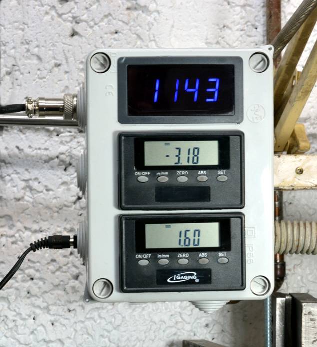
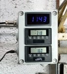
    From the top, tacho, X axis DRO and Z axis DRO. Fitted to a plastic electrical junction box from a hardware store.

    The DROs are normally powered by two 3 v button cells in parallel and it is always annoying when the batteries go flat and you are out of spares.
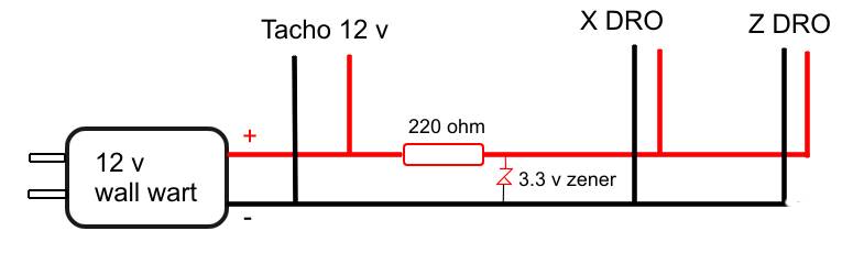
    The tacho needs to be fed on 8 to 24 v DC.
    I had a 12 v wall wart which I planned to use for the tacho and as all displays were in the same box it seemed only sensible to toss the batteries and feed the DROs from the same source as the tacho. A 3.3 v zener diode and a 200 ohm resistor was all that was necessary to drop and regulate the supply to the DROs as shown in this diagram.

    Lathe tacho and DRO cluster.-tach-dro-04.jpg

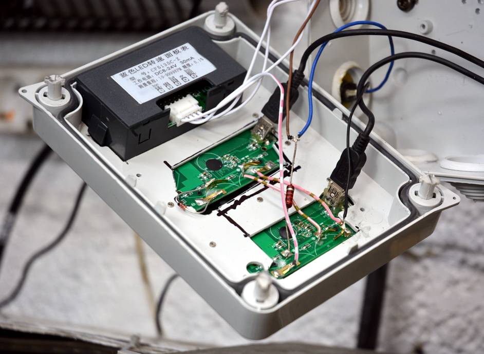
    I junked the backs of the DROs, cut component clearance holes in the box lid and used the original screws to hold them in place. i soldered connecting wires directly on to the battery clips. The tacho was designed for panel mounting and so needed no further attention other than cutting the appropriate size hole.
    A three pin socket was added for the tach pickup and a socket for the supply from the wall wart.

    Lathe tacho and DRO cluster.-tach-dro-02.jpg

    Lathe tacho and DRO cluster.-tach-dro-03.jpg
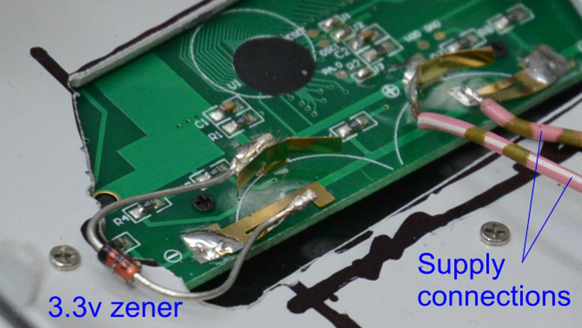
    Closeup of the power connections to one of the DROs.

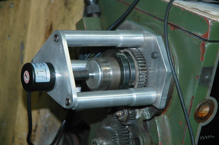
    Sometimes I need to mount a rotary encoder to my spindle and so I needed a method to attach the tach pickup and magnet which would still allow this and space was a bit tight.

    Lathe tacho and DRO cluster.-rotary-encoder-01.jpg
    Rotary encoder which is sometimes needed.

    Lathe tacho and DRO cluster.-tach-dro-07.jpg
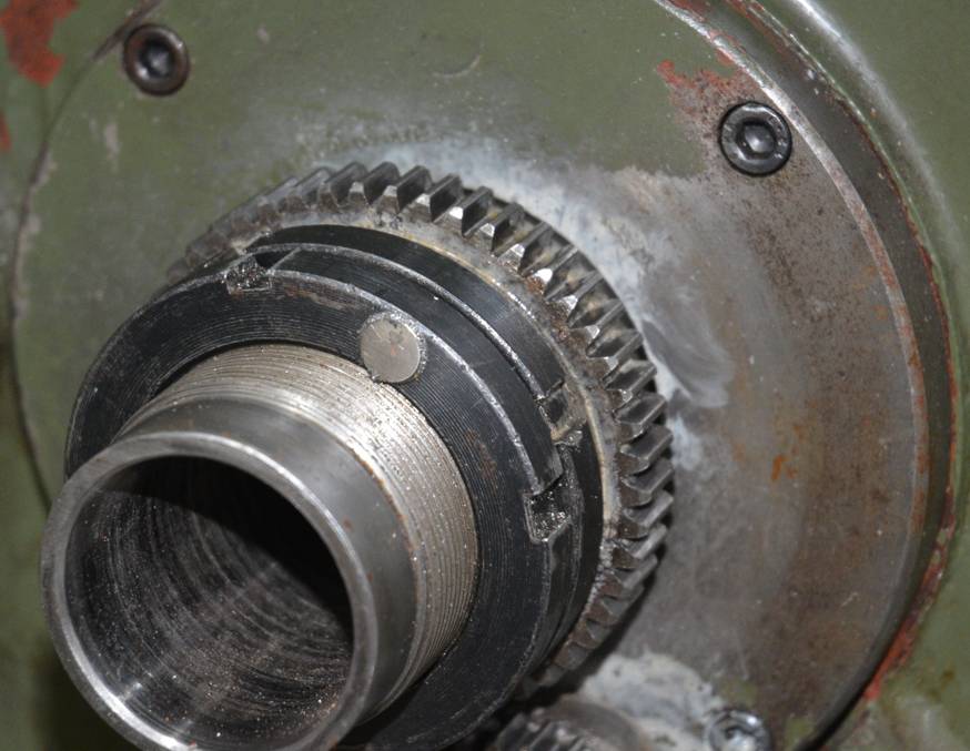
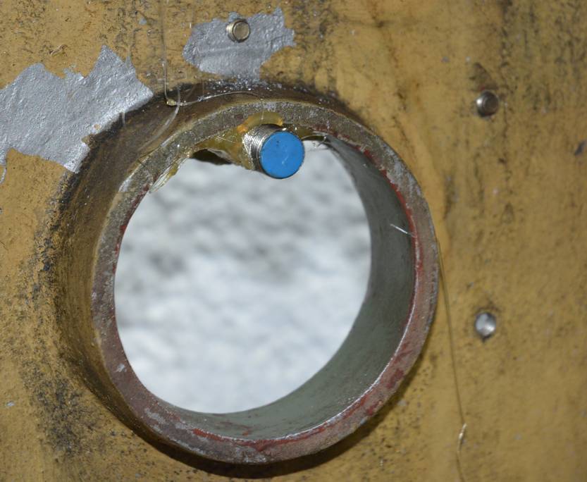
    The magnet for the tach pickup was inset into the spindle lock nut.

    Lathe tacho and DRO cluster.-tach-dro-05.jpg Lathe tacho and DRO cluster.-tach-dro-06.jpg
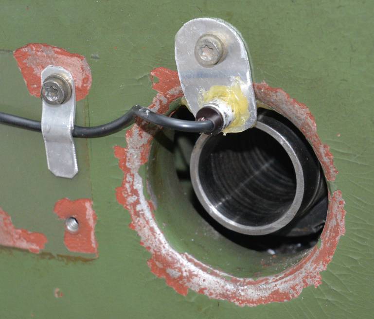
    The pickup was hot glued to the cover, with a security plate on the outside. This allows the pickup to swing completely out of the way when the cover is opened, thus allowing unhindered use of the encoder.

    Warning: The tach pickup is sensitive to the polarity of the magnet. With the magnet facing one way it will work OK, turn the magnet over and it will not work. So prior to final fitting of the magnet you can manually move the magnet back and forth across the pickup to check if the display counts up. There is a small red LED on the back of the pickup which will increase in brightness when the magnet is placed on the end of the sensor with the correct polarity.

    186 More Best Homemade Tools eBook
    Last edited by tonyfoale; Apr 10, 2019 at 01:48 AM. Reason: Added content on magnet polarity.

  2. The Following 5 Users Say Thank You to tonyfoale For This Useful Post:

    DIYer (Apr 9, 2019), high-side (Apr 10, 2019), Jon (Apr 9, 2019), Paul Jones (Apr 9, 2019), Tule (Apr 10, 2019)

  3. #2
    Content Editor
    Supporting Member
    DIYer's Avatar
    Join Date
    Aug 2013
    Posts
    3,056
    Thanks
    773
    Thanked 1,852 Times in 1,653 Posts


    Thanks tonyfoale! We've added your DRO and Tachometer Cluster to our Digital Readouts category,
    as well as to your builder page: tonyfoale's Homemade Tools. Your receipt:


    2000 Tool Plans

  4. #3
    Supporting Member Paul Jones's Avatar
    Join Date
    May 2014
    Location
    Del Mar, California
    Posts
    1,231
    Thanks
    5,810
    Thanked 1,441 Times in 655 Posts

    Paul Jones's Tools
    Tony,

    Nice comination of digital displays.

    I made the simple lathe RPM speed measurement method with something similar for my 12" swing lathe at http://www.homemadetools.net/forum/1...6430#post22140 and also first doing this for my 7" swing lathe at http://www.homemadetools.net/forum/m...3147#post15859 . Both methods are the Hall Effect sensors using magnet attached to the spindle lathe. In fact I re-modified the magnet mounting when I added the 12" swing lathe with a rear spider mounting http://www.homemadetools.net/forum/l...896#post105741 . I only use the lathe RPM display to double- check I set the mechanical gear-head RPM selections correctly.

    Regards, Paul

  5. The Following User Says Thank You to Paul Jones For This Useful Post:

    tonyfoale (Apr 10, 2019)

  6. #4
    Supporting Member tonyfoale's Avatar
    Join Date
    Nov 2016
    Location
    Spain
    Posts
    1,566
    Thanks
    689
    Thanked 2,646 Times in 709 Posts

    tonyfoale's Tools
    Quote Originally Posted by Paul Jones View Post
    Tony,

    ........ I only use the lathe RPM display to double- check I set the mechanical gear-head RPM selections correctly.

    Regards, Paul
    Paul,

    I fitted the tach in anticipation of swapping the 1 ph drive motor for a 3 ph one controlled by a VFD. The VFD will have a readout but that will only show frequency or motor (not spindle) rpm. These tacho displays are so cheap that there is little reason not to use one.
    Yesterday I scored at auction a 5 hp 1500/750 rpm 3 ph motor which will suit the lathe nicely.


    186 More Best Homemade Tools eBook

Thread Information

Users Browsing this Thread

There are currently 1 users browsing this thread. (0 members and 1 guests)

Tags for this Thread

Bookmarks

Posting Permissions

  • You may not post new threads
  • You may not post replies
  • You may not post attachments
  • You may not edit your posts
  •