
 LinkBack URL
 About LinkBacks


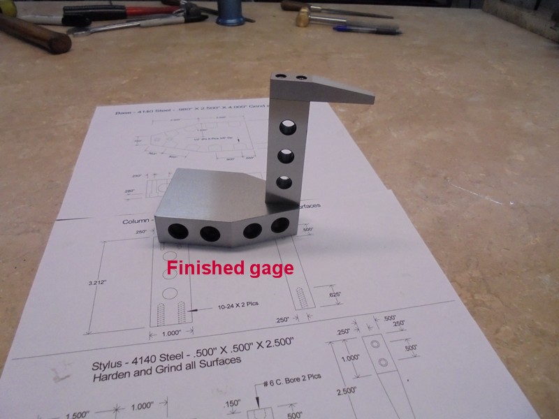
There are numerous ways to set a lathe tool on center to the lathes axis, the height setting gage I came up with is by no means a new method, but I think it is one of the most simplest and easiest to use gages and by far the most accurate, it consists of only three parts, the base, column, and stylus (plus four socket head cap screws)
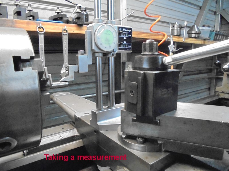
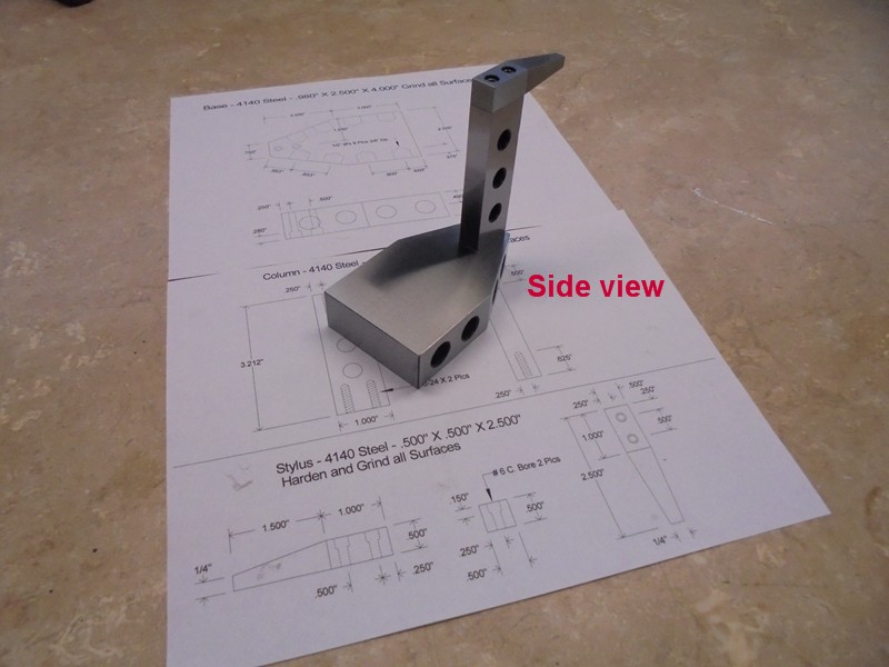
The way I came up with the height of the gage was to take a measurement from the top of the cross slide on the lathe carriage using a height gage to the top of a 1/2 dowel pin chucked in the lathe, then subtract one half the diameter of the dowel pin, the measurement I had on my lathe was 4.442 - .250 = 4.192 this is the total height I made my gage from the bottom of the base to the top of the column. (See photo)
Depending upon what manufacturer of lathe you own you may not have a ground flat cross slide, in that case you could lay a couple of parallels across the bed of your lathe and measure from there, however it doesnt matter where you take your measurement from, where ever you take your measurement from is where you will have to use the gage every time to set the tools height.
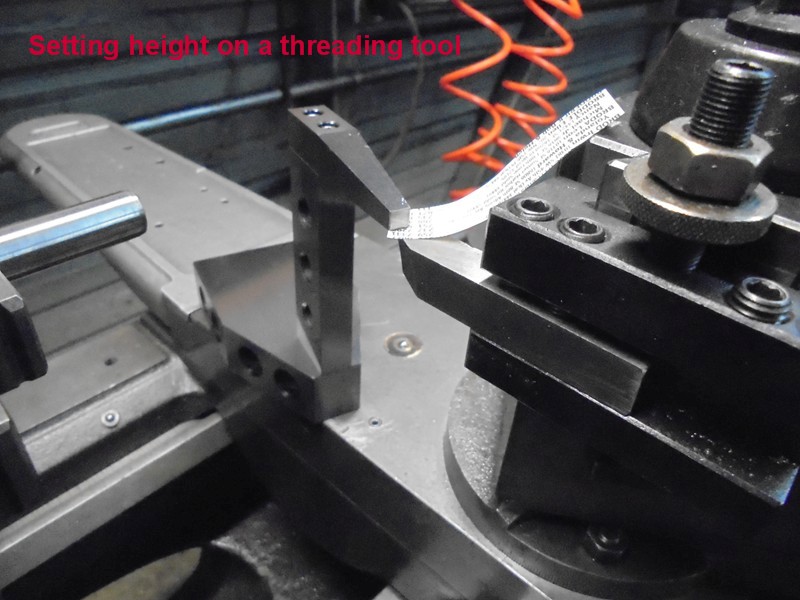
I made the gage heavy and ridged enough so it wouldnt be easy to lift by adjusting the tool bit, in other words you can feel the tool bit touch the bottom of the stylus before it starts to lift the gage, I use a piece of phone book paper (which is .002) as a shim between the top of the tool bit and the bottom of the stylus, once I felt a drag on the shim I removed it and turned the adjusting screw on the BXA tool holder just a fraction and locked it down, think of it like setting the gap on a spark plug. (See photo)
This height gage will work on any tool holder, those who use a rocker type tool post will find this gage very useful, those using a rocker type are always adjusting the height of the tool every time you resharpen and reinstall a bit.
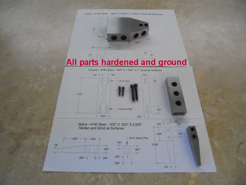
The entire unit was made from 4140 steel; all parts were hardened and ground, though it could be made from mild steel, however hardened steel is just less easy to ding, scratch and rust, the stylus should be made from a heat treatable steel, reason being that a soft steel stylus would be gouged by the tool bit creating burrs resulting in an inaccurate reading,
I have included two drawings along with multiple photos on the construction of this tool; the height of the column will have to be adjusted to ones own needs.
As always thanks for looking
And happy Machining
Doug
Calculating the height to make the gage
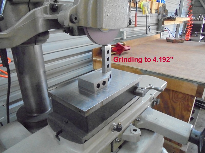
Grinding in the final height
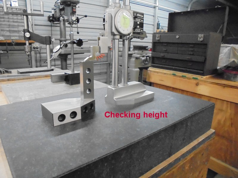
Checking the height
Setting the height of a 60° threading tool, this method would apply to all cutting tools
All parts made, hardened and ground
Assembled
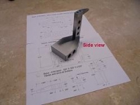
Another angle
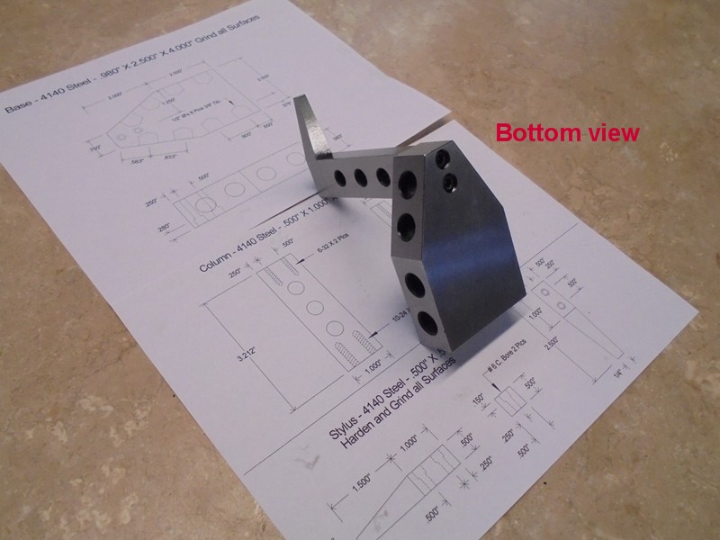
Bottom view
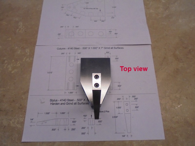
Top view
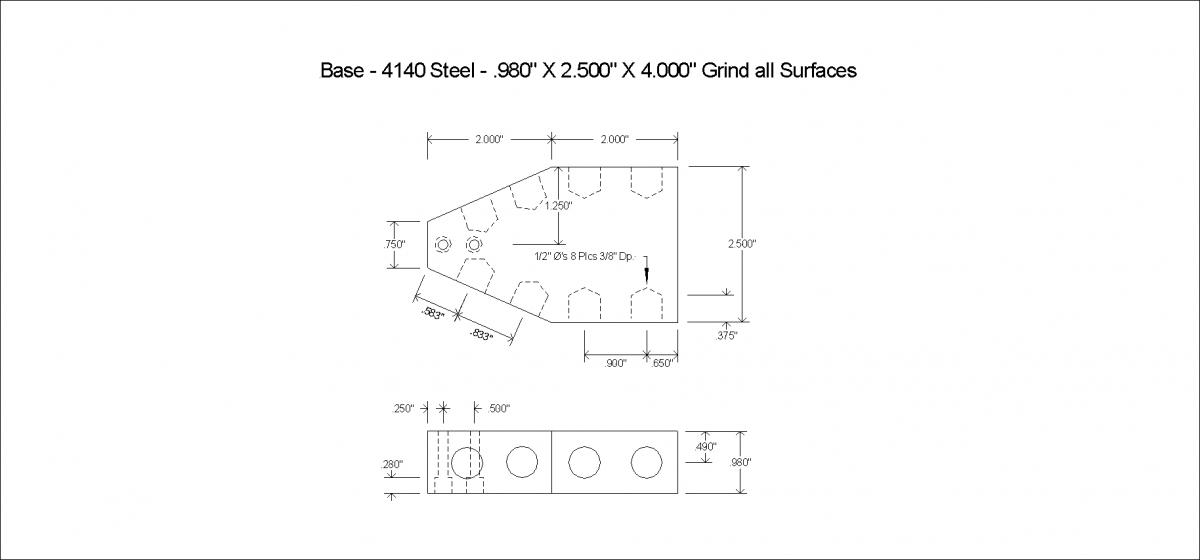
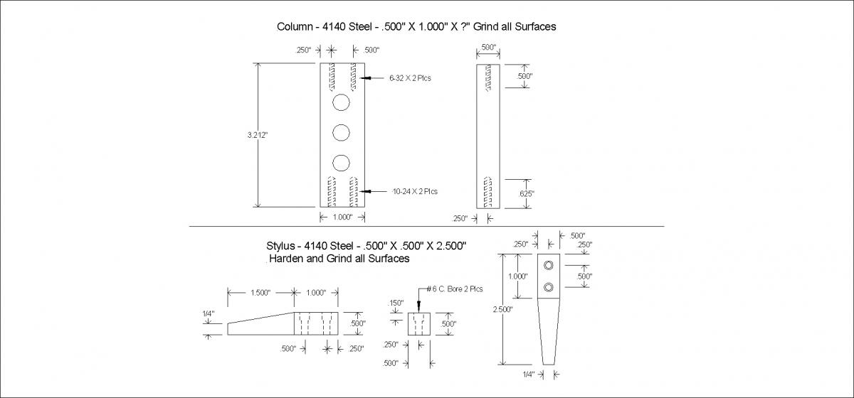
Drawing 1
Drawing 2


 Reply With Quote


Bookmarks