
 LinkBack URL
 About LinkBacks


I hope this works as I have had great difficulty trying to understand how to put up a post. It is not as straight forward as I would like to see. I would like to see the attachments on the page for the comments rather than just links.
I am interested in the restoration of stationery engines. With that comes the need to time the magneto to the correct position Before Top Centre. This can be done by using cigarette paper between the magneto points so that when crank shaft is turned in the direction of rotation the paper will be released as the points open. This can be difficult to do on ones own on a large engine when a lot of effort may be needed to turn the crankshaft, leaving no hands to provide tension on the cigarette paper.
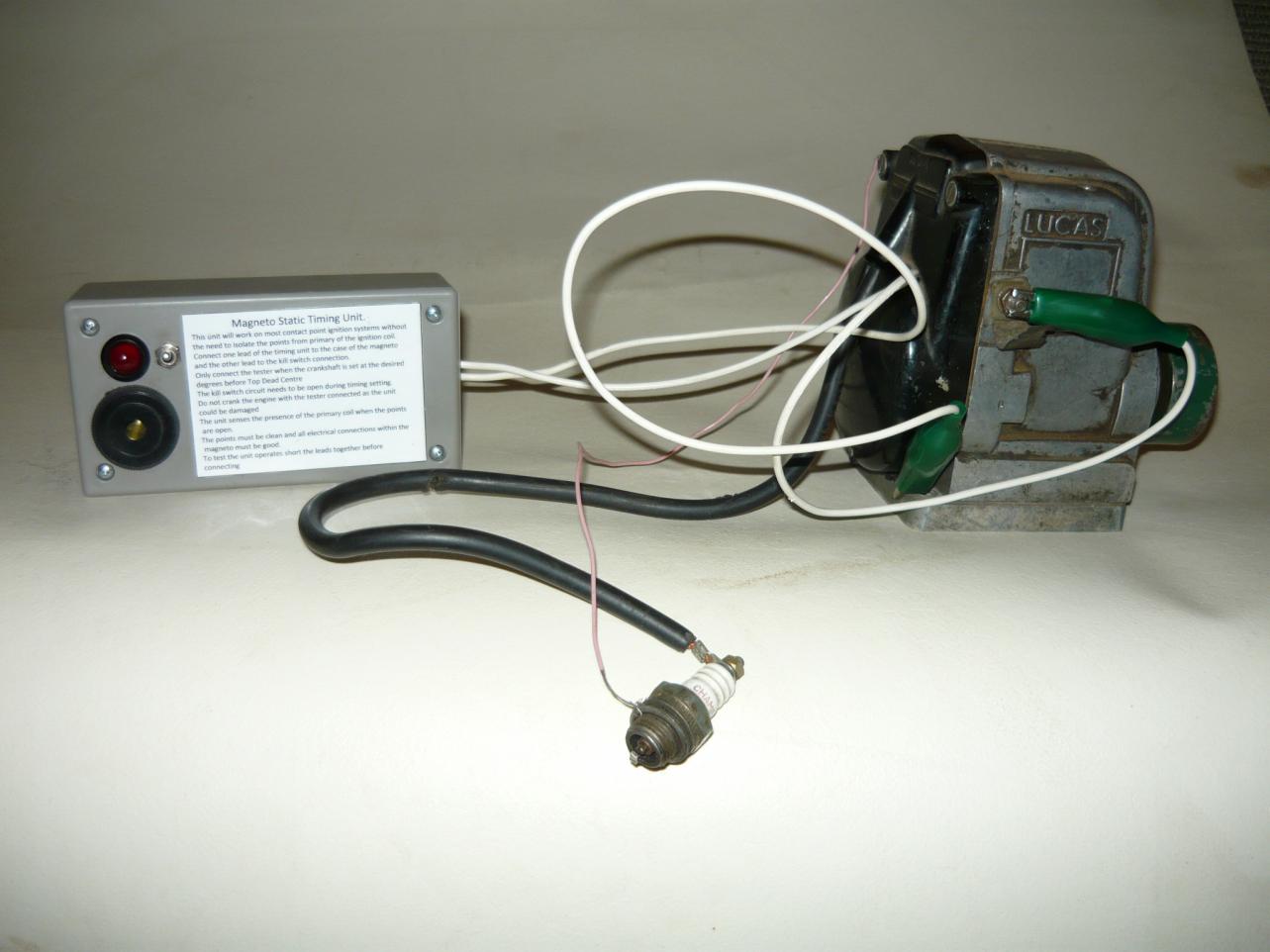
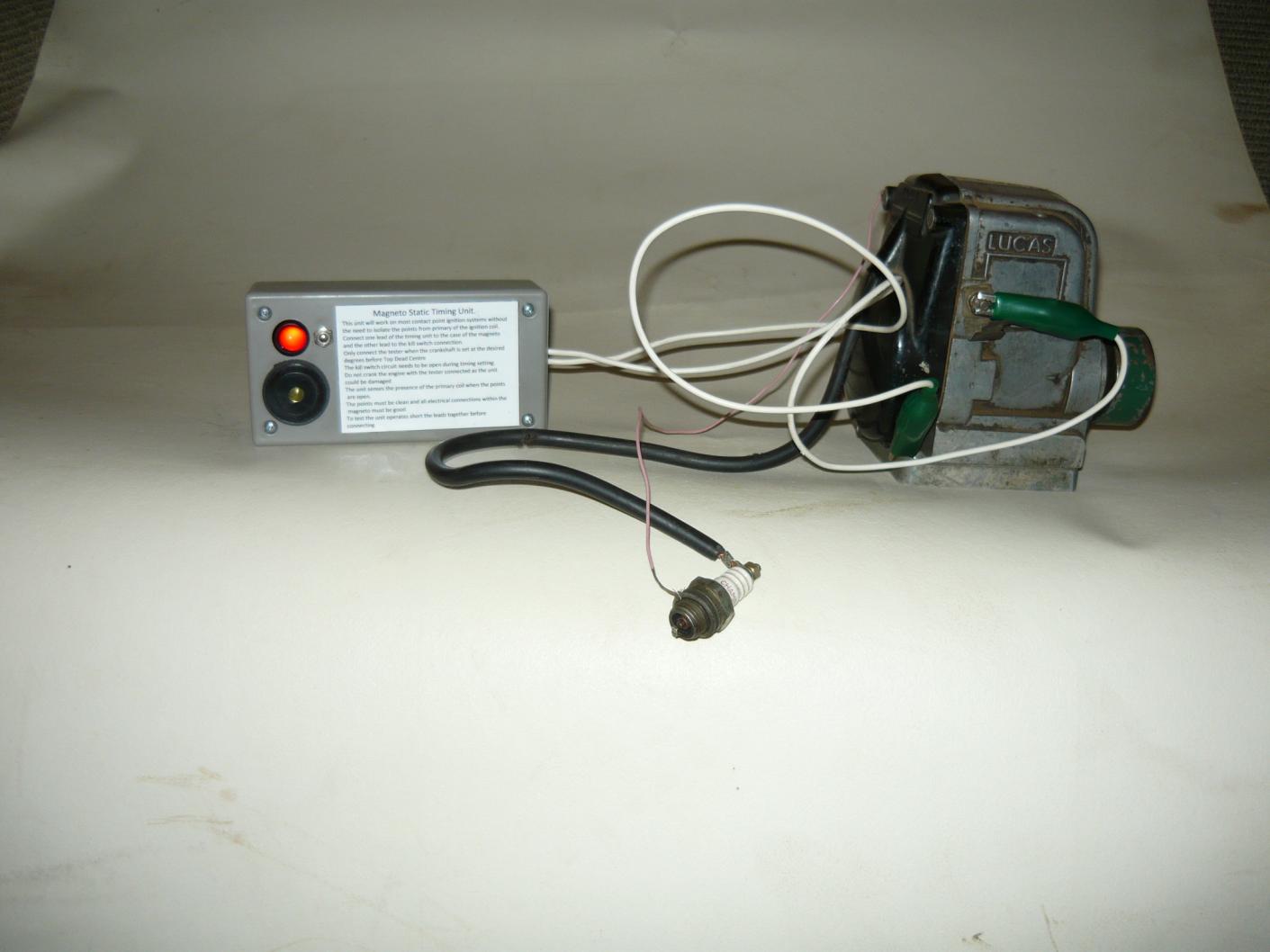
One sense that is available is hearing, but a simple battery and buzzer will not work because the resistance of the magneto primary coil, which is across the points when they are open, is only a few ohms and the buzzer will operate even with the points open. To this end I built this unit.
It is similar to that which is used in the aeronautical industry to synchronise twin magnetos on piston engines and it has a light and a buzzer to give indication of its status.
The principal of operation is that the unit senses the inductive reactance of the primary coil of the magneto when the points are open. To use the unit the one lead is attached to the kill switch terminal and the other to ground. With the crankshaft rotated well before the firing angle the unit will show no light nor sound, because the points are closed. Turning the crankshaft to the firing position the points will open the light will illuminate and the buzzer will sound.
I am by no means an electronic expert and it is thanks to Google that I found the basis of this circuit. With the assistance of my local electronics store I was able to measure the inductance of the primary coil of a typical magneto that I use, this was 43.5mH ( millihenries). My search was for a circuit which sensed inductive reactance of that size and I found a circuit that I understood and could alter the values of, to those that suited my needs. So far I have found only one coil that it will not work on and that is for a modern motor cycle ignition and I am not into motor cycles.


 Reply With Quote


Bookmarks