Free 186 More Best Homemade Tools eBook:  
Get 2,000+ tool plans, full site access, and more.

User Tag List

Page 3 of 3 FirstFirst 1 2 3
Results 21 to 23 of 23

Thread: Racecar project and chassis jig

  1. #21
    Supporting Member
    Join Date
    Apr 2015
    Location
    NSW,Australia
    Posts
    25
    Thanks
    3
    Thanked 65 Times in 15 Posts

    Astro's Tools

    Some More updates

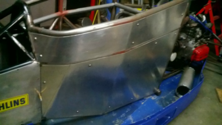
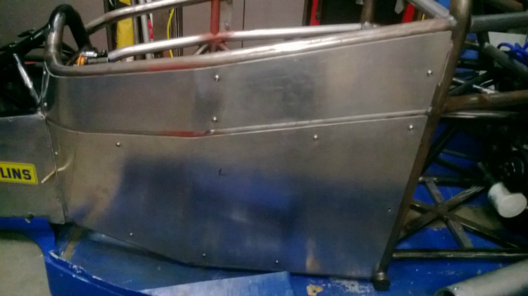
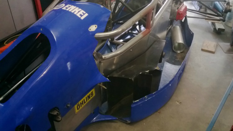
    Some more progress on the car. Made new inner body panels and mounts, these really soaked up a lot of time.Racecar project and chassis jig-ip1.jpgRacecar project and chassis jig-ip2.jpg
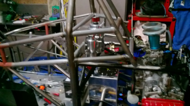
    Fitted an new fuel tank, header tank and oil catch can.
    Racecar project and chassis jig-ht1.jpgRacecar project and chassis jig-ht2.jpg
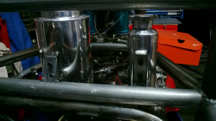
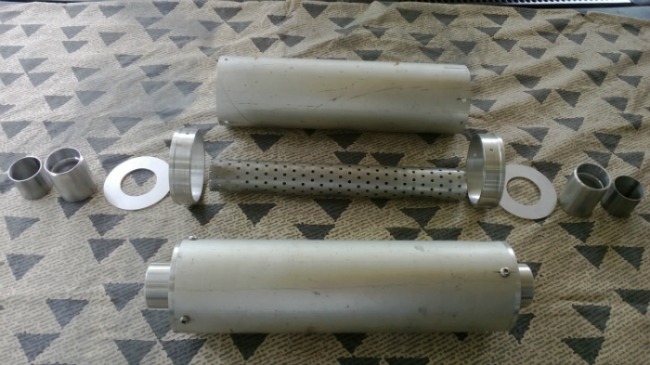
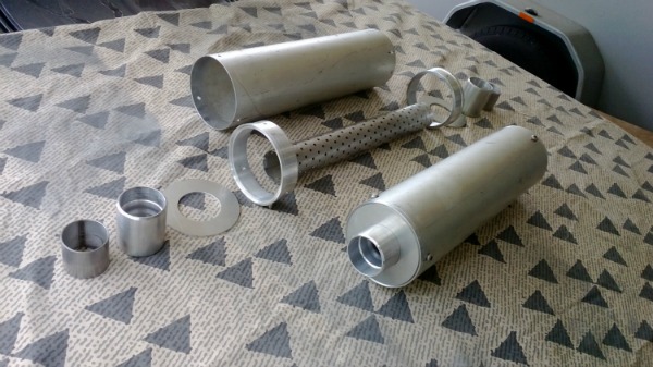
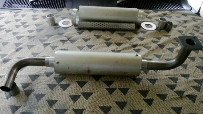
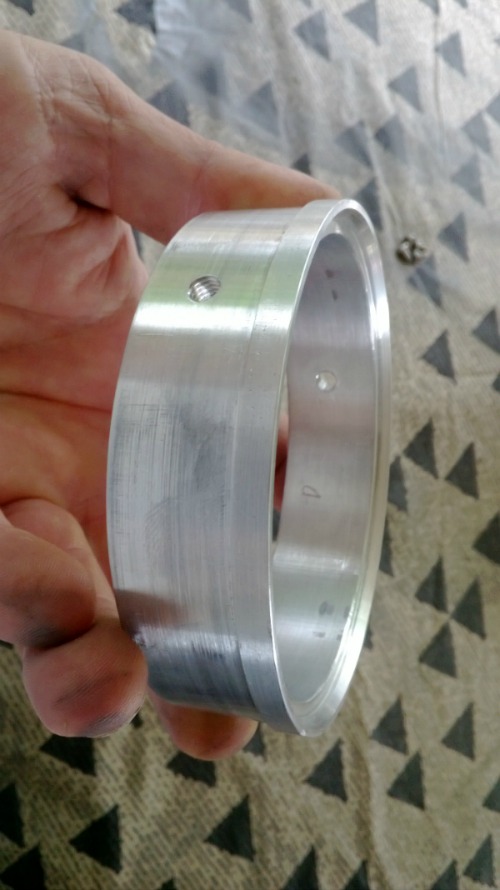
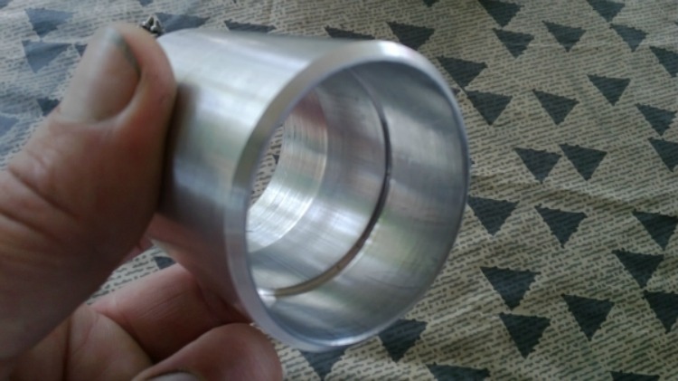
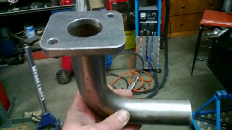
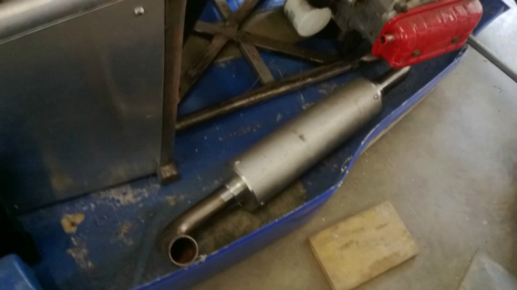
    I am making my own mufflers as I could not get commercially available ones to suit what I wanted. The main muffler body is 100mm by 1.5 wall, I had intended to machine the end caps from 1 billet but that was going to become expensive so I machined end cap rings from 100mm x 6mm wall tube, the rings were tapped m6 in 3 positions on each cap to allow me to disassemble to repack the mufflers. and made end plates from 3mm plate. The end cap socket I made from 50mm x 6mm wall, they were bored to fit the perforated tube on one end and an adaptor sleeve on the other end which will be welded to the exhaust tube. are all yet to be welded together. Just hope the sound is OK.
    Racecar project and chassis jig-ex6.jpgRacecar project and chassis jig-ex5.jpgRacecar project and chassis jig-ex2.jpgRacecar project and chassis jig-ex3.jpgRacecar project and chassis jig-ex4.jpgRacecar project and chassis jig-ex7.jpgRacecar project and chassis jig-ex1.jpg
    I decided to run the exhausts forward in the body exiting out the side of the undertray, this made the exhausts much easier to make rather than running them through the suspension links and out the back.
    I have cut the original fibreglass bodywork to allow widening and am in the process of fitting all of that together with radiator ducts and new mounts.Racecar project and chassis jig-xp1.jpg
    OK, back to the shed for now.

    186 More Best Homemade Tools eBook

  2. The Following 3 Users Say Thank You to Astro For This Useful Post:

    Jon (Jan 25, 2016), kbalch (Jan 25, 2016), PJs (Nov 8, 2016)

  3. #22
    kbalch's Avatar
    Join Date
    Jun 2012
    Location
    Clermont, FL
    Posts
    5,034
    Thanks
    2,275
    Thanked 531 Times in 383 Posts
    Great progress and excellent work! I'm really looking forward to seeing it running.

    Ken

    2000 Tool Plans

  4. #23
    Supporting Member
    Join Date
    Apr 2015
    Location
    NSW,Australia
    Posts
    25
    Thanks
    3
    Thanked 65 Times in 15 Posts

    Astro's Tools
    I needed to make new radiator tubes to suit the longer chassis from 1.25inch aluminium tube. It would have been easier to re-create the existing cooling circuit, but this was designed to have the two radiators in series rather than in parallel, and from my research I learned that parallel was the superior configuration. New pipework was made using my homemade tubing bender and bead roller. The thermostat housing located on the inlet manifold was modified to re-position it for a more favourable hose path. Mounts were welded to the chassis to accept 32 mm P clamps to support the radiator pipework. A temperature sensor was incorporated into the top hose run.
    A new aluminium dash panel was fabricated to house a mycron3 digital dash unit. Although the car came with adjustable brake bias, the cockpit adjuster was a bit basic. A tiny little knob was used with no detents. A new larger bias adjusting knob assembly was made with detents.
    The clutch was actuated by a heavy duty cable which was routed between the rear shocks and anti-roll bars. This installation had caused some interference with the roll bar links so a solution was needed. I could not find a suitable location for the cable which did not cause obstruction of some sort, so a hydraulic conversion was undertaken. This entailed mounting a master cylinder to the front bulkhead, strengthening the bulkhead in this location to cope with the increased load of clutch actuation and finding a suitable slave cylinder to operate the clutch fork. The first couple of tasks were quite easy to accomplish, but obtaining a slave cylinder to mount in a suitable manner became frustrating, to the point where I decided that the only way to make this conversion work, was to manufacture a slave cylinder myself. The difficulty with this installation was that the cylinder had to mount to a plate parallel to the bellhousing, but the clutch fork operated at a compound angle in two planes. I made some mock up cylinders first to check measurements and clearances, then when all was good, I made two cylinders from aluminium. Two, because you can always use a spare.
    I have the fiberglass bodywork mostly complete but still some work to go. The original bodywork needed some freehand blending which was helped by the use of polyurethane foam blocks and some flat fiberglass sheet which I laminated. When finished to a final shape this was glassed over and the foam was removed from the inside and glassed on the inside. I could have left the foam in place but polyurethane foam creates a cyanide gas when burnt. Not that I intend burning the thing, but you never know.
    The side pod bottom edge was raised by 10mm to allow more support around the dzus fastener holes as the old ones were very close to the edge and cracked easily. Exhaust outlet flanges were fitted to the undertray and will be riveted on. New mounts have been made for the nose hatch which allows access to the shocks and pedal assemblies.
    An air box was fabricated in fiberglass, incorporating a flat panel filter to feed the two Hitachi carbs, as originally they were fitted with tall ram tubes and only a stainless steel mesh covering them to keep out the small rocks and insects. As I intend running this car at some less than ideal venues, I figured a filtered engine intake would be the way to go. The mould for this air box came from the local dollar shop in the form of a rectangular plastic tub. I plan to incorporate a couple of shorter ram tubes inside of the air box under the filter. Air inlets will be cut into the front and top of the air box when I finally have it bolted down.
    The original head rest was sectioned and raised in height and blended with the surrounding bodywork and air box.
    More photos to follow.
    Attached Thumbnails Attached Thumbnails Racecar project and chassis jig-exbody1.jpg   Racecar project and chassis jig-exbody3.jpg   Racecar project and chassis jig-exbody5.jpg  


    186 More Best Homemade Tools eBook

  5. The Following 2 Users Say Thank You to Astro For This Useful Post:

    Jon (Nov 8, 2016), PJs (Nov 8, 2016)

Thread Information

Users Browsing this Thread

There are currently 1 users browsing this thread. (0 members and 1 guests)

Bookmarks

Posting Permissions

  • You may not post new threads
  • You may not post replies
  • You may not post attachments
  • You may not edit your posts
  •