 LinkBack URL
 About LinkBacks
Have you given any thought to a hard turning insert?


Have you given any thought to a hard turning insert?


I don't know how hard the spindle is. I'm guessing better then Rc55 (probably near 60). I have a Rockwell hardness tester (and heat treat furnace).
That and a boring bar to support the 5 inch cantilever cutting force is pretty big. The length of the spindle taper is a little over 4.5 inches. The deepest cut would be slightly over .002 (a skim to correct for the .0045 runout fit of the sleeve), which I don't know how good the surface finish would be after this.
From past experience using carbides, steel of Rc35 and more, I found to be a limit where the tooling was not destroyed. That has been my experience. I'm not using the most expensive inserts, and I really hate it when I have a $60 insert and it's instantly destroyed very few lathe tools have expensive (e.g. Iscar) inserts for that reason). Most of my insert tooling is on the mill, and I use brazed carbide mostly on the lathe.
This just seems to be a task that should use the tool post grinder. At least it will take several attempts to destroy it, where only one pass with a carbide can achieve the result.
I know I can find these grinding wheels. I need to solve the problem either way, assuming I ever need to do internal grinding work.


Rc 60 +/- is probably quite close. One lathe at a vo-tech I taught at had a spindle adapter for a collet closer that was not concentric. Off by 2 or 3 thou, but that was too much IMHO. This was before hard turning became a thing so I just used a standard cemented carbide boring bar for the repair. It worked and I had collets running much closer to zero TIR. BTW, it was also around 60 Rc.
So if push comes to shove and you cannot find a wheel at least there is a plan B.
Here's a link to a site offering good info on hard turning/boring. http://www.superprecision.com/hardtu...echniques.html
But if you screwed the cut up, it was a removable collet adapter, not the spindle directly. That is my fear, I want to fix it, not really mess it up.Originally Posted by Dr Stan

I can't find any metric wheels for this. But I can make a simple adapter nut to use a straight cup recessed wheel with a SAE arbor size. Something with a 5/8 or so hole, just needs to be bigger then the 10mm to allow enough annulus for a 10mm thread, 1/2" or bigger (too close to 3/8").
The blue color is the grinding wheel, the nut can stand proud of the wheel, and have flats vs the pin spanner wrench holes. Either one requires milling machine work.
Sorry I'm using OpenOffice Draw to make this diagram. I do miss AutoCAd from work, but to pricey, and I don't do much line drawings outside of pencil sketches for my use. I could not figure out how to do shading of a line drawn area. So the side view the nut is white, but the top view it's blue gray. First time I've tried to use this tool. The tool lets you fill a hashed color for the donut object, but not a box, go figure.
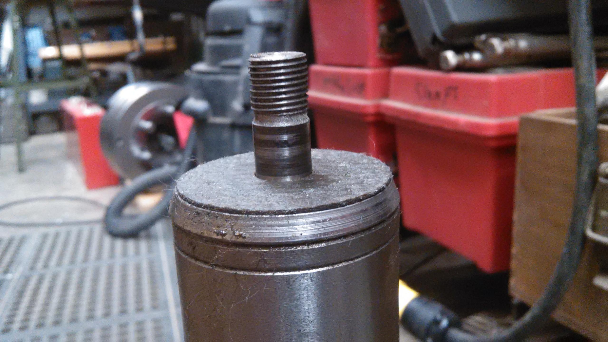
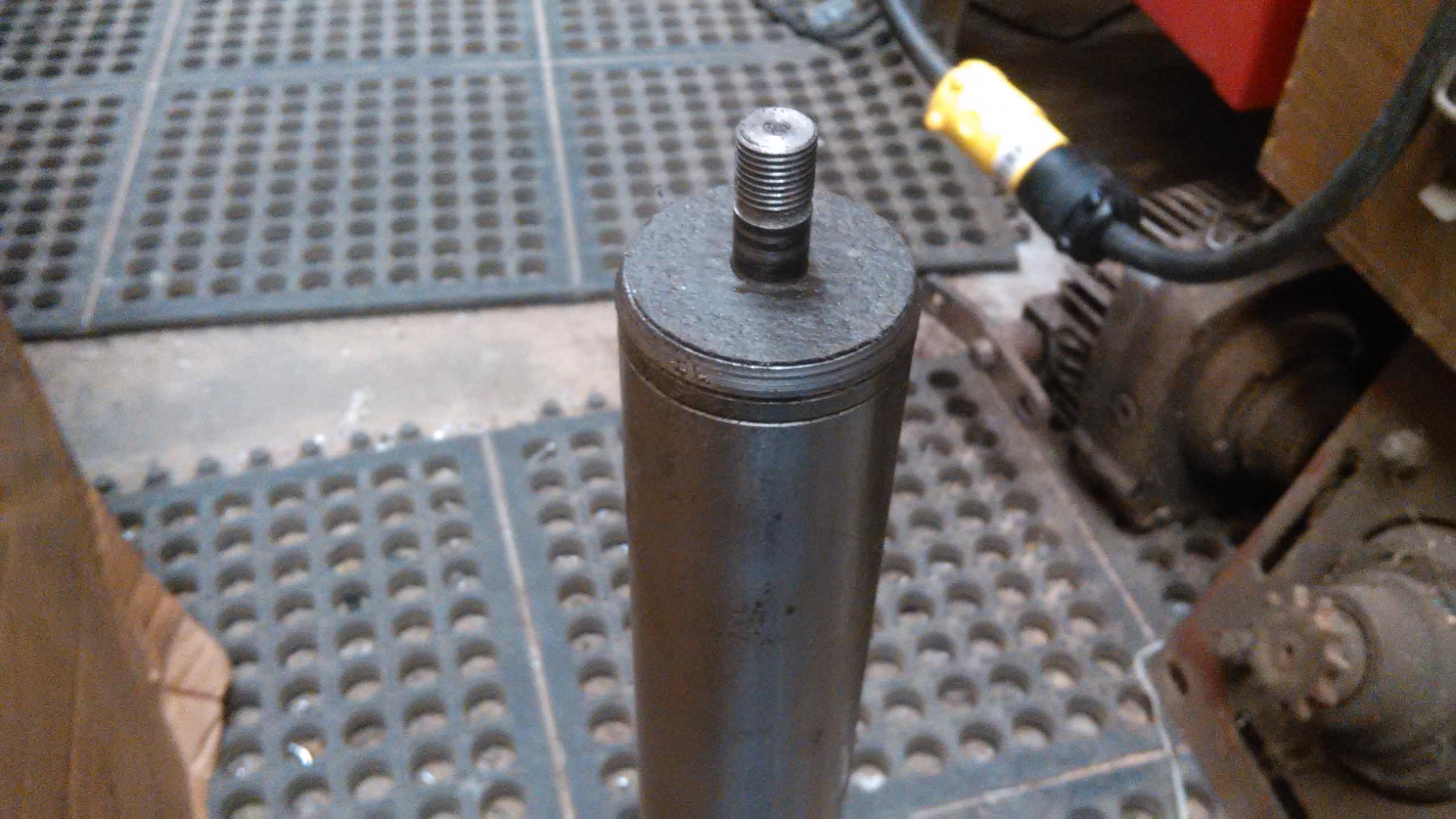
A photo of the ID TPG arbor:
This arbor is 10mm diameter.

Last edited by metric_taper; Mar 19, 2017 at 08:22 AM. Reason: add photo of TPG arbor

Good point about the difference between an adapter and the spindle itself.
BTW, you may want to look at DraftSight. I use their free 2D version as that's plenty for what I do. 3D versions are also available at a price. The 2D version is very close to AutoCAD even to the point of using many of the same shortcuts, commands, etc.
Did I mention its free??????????
Another thought. Would a #4 or #5 MT be big enough in the spindle? One could make an adapter to fit the existing taper then drill & bore it for the MT. Just have to have a witness mark on the spindle nose & the adapter for it to run true when removing & inserting the adapter.
Last edited by Dr Stan; Mar 19, 2017 at 02:47 PM.
Stan, thank you for the 2D link. I'm downloading it now.
The current sleeve has a #4MT center, I see from bluing it fits OK, not optimal, but not driving torque can live with it. I did not check to see if the 4MT hole is off relative to the sleeve fit. I hope that is not another alligator. But I certainly could regrind the center and make 'timing' marks as you indicate.
I didn't get much done today, but will spend the evening making an indicator holder to see if I can get an accurate enough measurement of the spindle taper (I have a 1" size dial, Federal indicator .01mm resolution, short travel, that is short enough to fit inside the hole).
I had an undetected fire in the attic space of the house in the early morning hours. The attic is insulated, and this is a computer room. I use a milkroom heater. The thermostats on them are unable to control room temp. So I ran it through a digital electronic one (STC 1000 off eBay). Looks like the relay started arching and it did a melt down. I smell of the magic smoke. Lucky the plastic housing was flame retardant. But the thermistor wire was not, and it burned like a fuse, which laid across the power wire, and caused the main circuit breaker to trip. Which was a good thing, as the arcing ended. So I spent the day making a new thermostat, and using a solid state relay for the main control. I had started that project many weeks back, which was forced to be finished today. And now I will install a fire alarm and connected it to the other ones.
Draftsight did not like my OS. BUT I found LibreCAD, which I'm familiar with their MS OFFICE freeware. It's installed but I need to play with it. Also found FreeCAD, and installed it as well, but don't know how hard it will be to learn. From photos it looks sorta like googles Sketchup.
Darn, you know how many hours you can spend in front of this 'confuser' and produce nothing all day. (I'm actually a pro at it).
I'll see how long it takes to make a 2D drawing. It can't be as irritating as OpenOffice Draw was. It kept changing to some default font size, and putting text exactly where I wanted took manipulation.
.
Yep humans can make mistakes, but it requires a computer to really screw it up. "Pin It")
Yep humans can make mistakes, but it requires a computer to really screw it up.
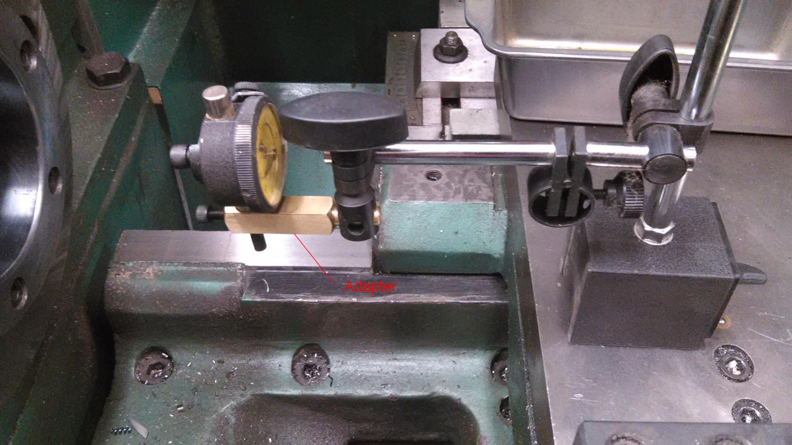
One of the tasks in fixing this was to measure the taper of the spindle. I have a Federal AGD 1 .01mm 6mm travel, that was small enough to fit inside the lathe spindle hole. I picked this indicator off eBay some time ago, but I never had any means to install it on any of my import DIN mag bases. All my AGD 2 indicators have a lug back, and so I can use the adapter that has a 7.5mm stud for attachment to the DIN holders. In this case these indicators have a snug between the 10mm extension arm and this indicator stud. I've tried to see if a snug between 3/8" and the 10mm exists, and had no luck. If I did find one, I would spend 3x what the cheep import holders cost me (or more).
So I made this adapter:
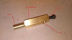
So here is the adapter setup to measure the spindle taper:
I was able to measure the spindle taper as 1:20, which is the double angle.
My measurement was at 40mm of carriage travel, 1.008mm indicator, and at 80mm 2.020mm. So I'm convinced this is a 90mm gauge line 1:20 metric taper. It may be off by a smidgen, or the setup of the cheep holder and angular cosine errors, as well the tip of the indicator not optimal for the surface.
If anyone here has a similar design for a AGD to DIN adapter, I could not find any examples by searching for DIN, AGD, indicator on this site.
My snug was in the way of the indicator, but I don't have any better snug then the one that came with this holder. I probably should have kept the brass square stock longer, but didn't want excess weight hanging out on the indicator arm.
There are currently 1 users browsing this thread. (0 members and 1 guests)
 Posting Permissions

 Reply With Quote
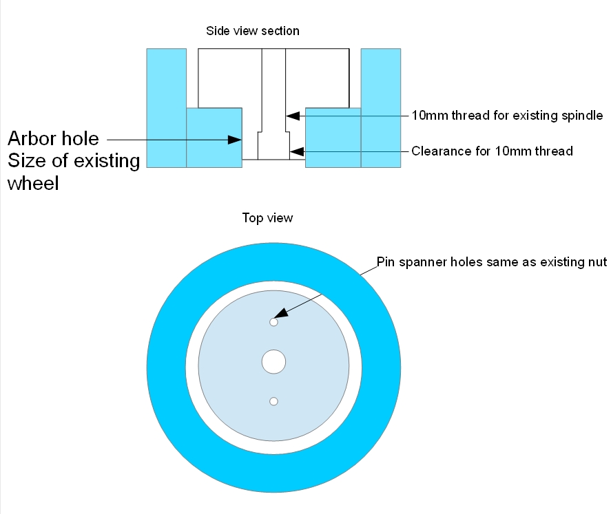

Bookmarks