OK, Thanks Tony. I've never seen one before, so you taught me something new.Quote:
Originally Posted by tonyfoale
Printable View
OK, Thanks Tony. I've never seen one before, so you taught me something new.Quote:
Originally Posted by tonyfoale
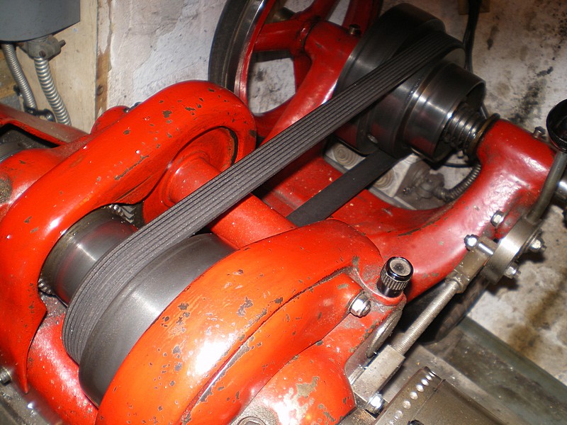
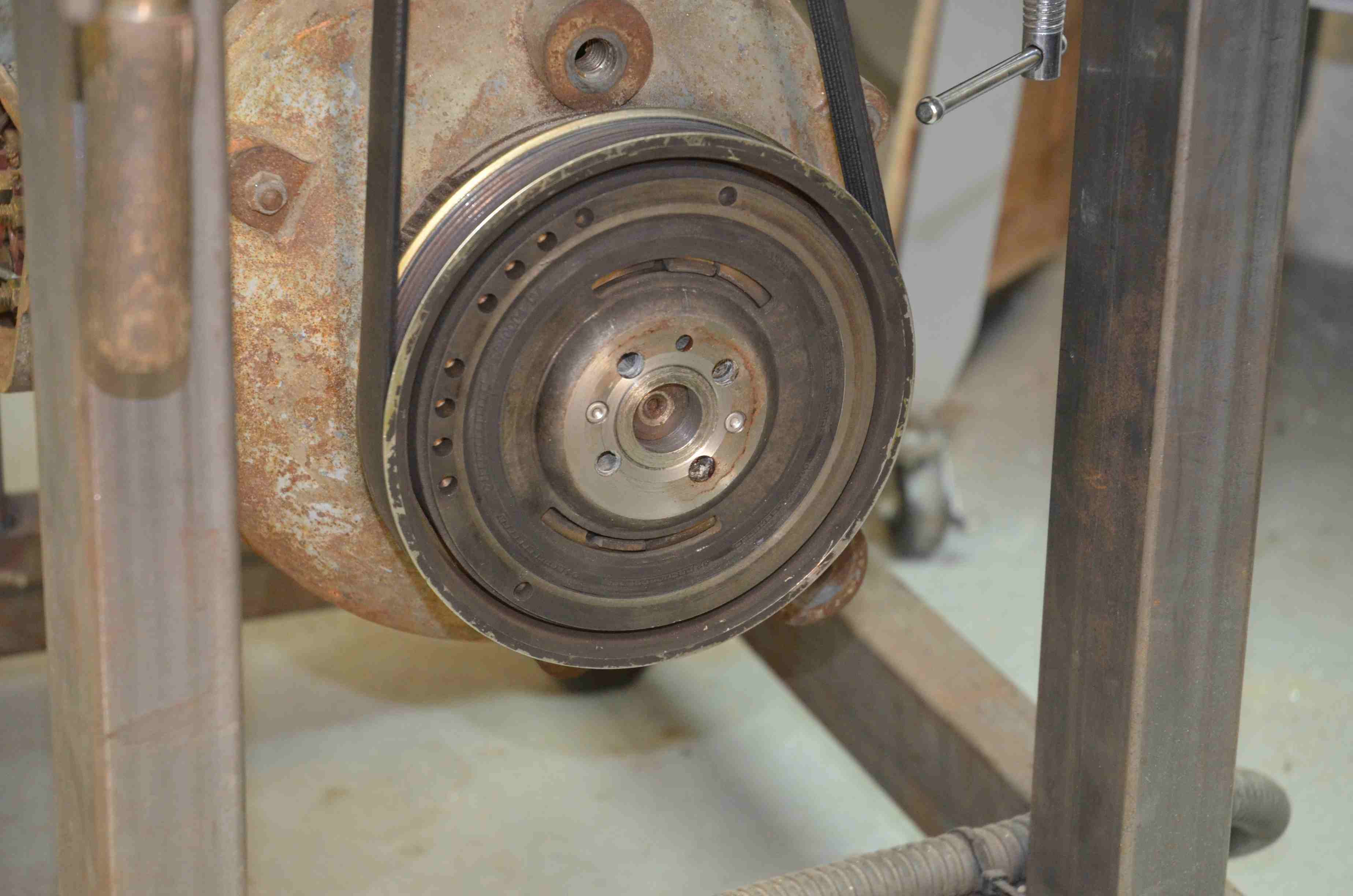
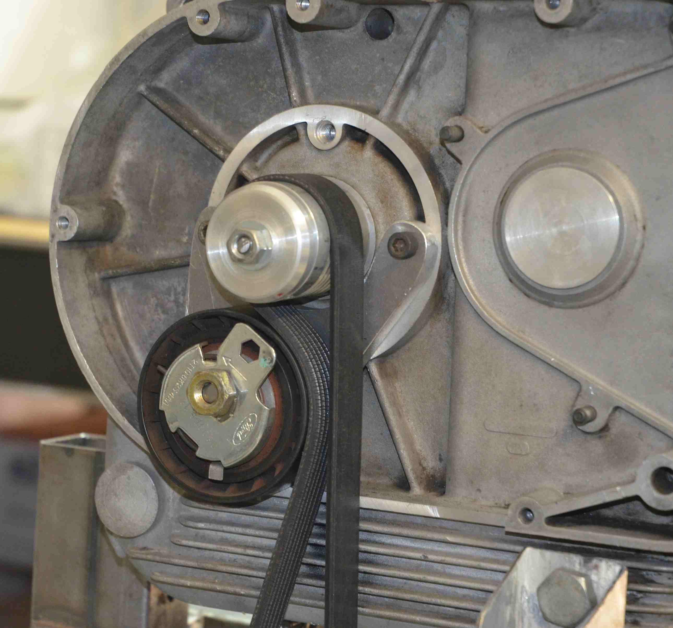
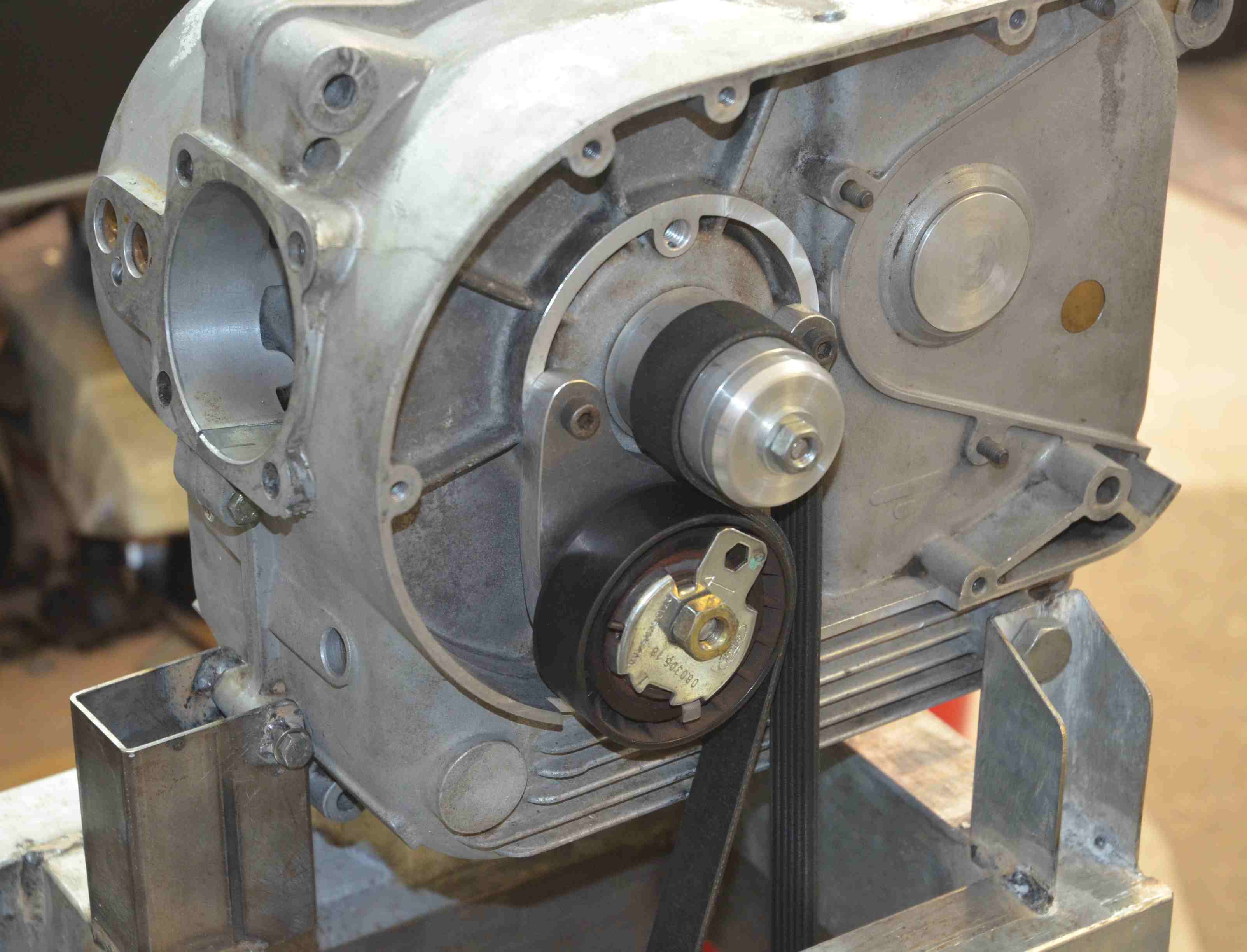
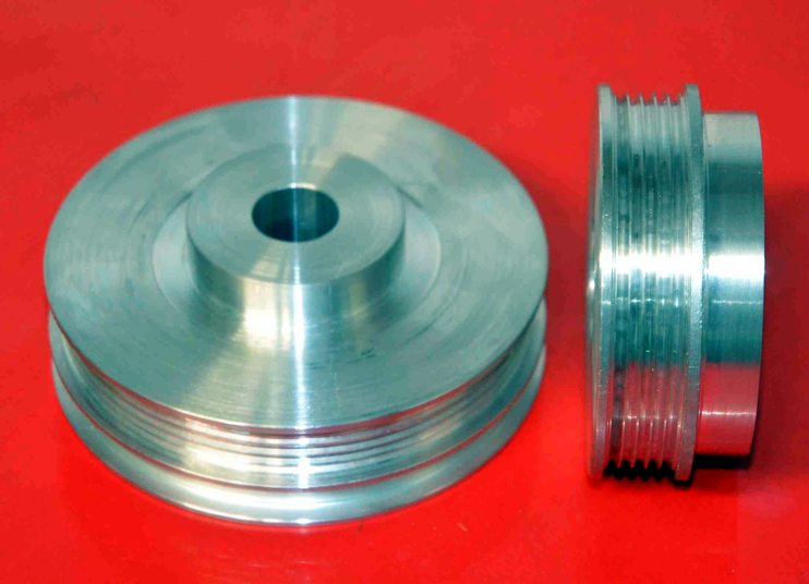
I use poly V belts wherever I can now, so far inside in though. They flex almost as well as a flat belt, and so can be used with small pulleys, they can deliver high torque without much slipping. Like flat belts they run smooth with little vibration. With small pulleys and the light weight of the belt they don't centrifuge off the pulleys much and so maintain their torque capability up to high speed. The pulleys are easy to make in a lathe, especially if you have a DRO.Quote:
Originally Posted by olderdan
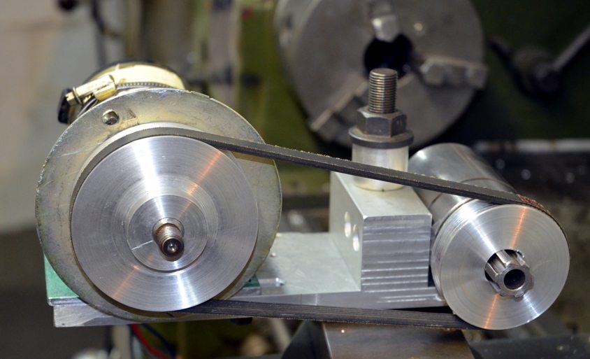
The largest one that I use is on a valve train test rig which I have spinning for long time periods at up to 12,000 rpm with about a 30 mm driven pulley, the driver pulley is around 140 mm. as seen in following pix.
Attachment 22977 Attachment 22978 Attachment 22979 Click thumb nails.
I used a much smaller one on my 5 hp. 6000 rpm Bridgeport as featured previously at http://www.homemadetools.net/forum/h...6661#post84115
Also on my multipurpose grinding head at http://www.homemadetools.net/forum/d...-grinder-67127
Attachment 22980 Attachment 22981
Thanks Tony.
I keep trying to reply to your thread about a lathe shearing tool but it shows up here. Anyhow, thanks for the info on the lathe shearing tool I will try it.
Shear tools have been used for some time by us shaper fans and I can vouch for the fine finish obtainable with my Elliot 10M.
More info from the very helpful NEMES web-site: Kay Fisher's Metal Shaper Column 43
Regards,
Brian
Thanks for the link. Interesting. The only time I used a shaper was in a technical training program that I went through when I worked for MIchelin in Lexington, SC. We had a project to complete using hand filing to a precise flatness and size and we were required to use a shaper on part of the piece. I still have it. I'll take a pic or two and post them if you would like to see it.
Yes please - if it's not too much trouble.
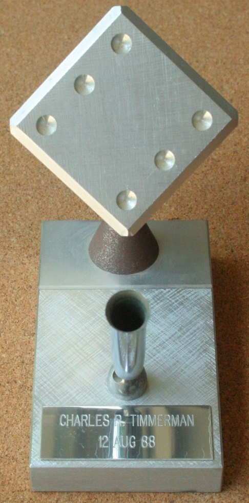
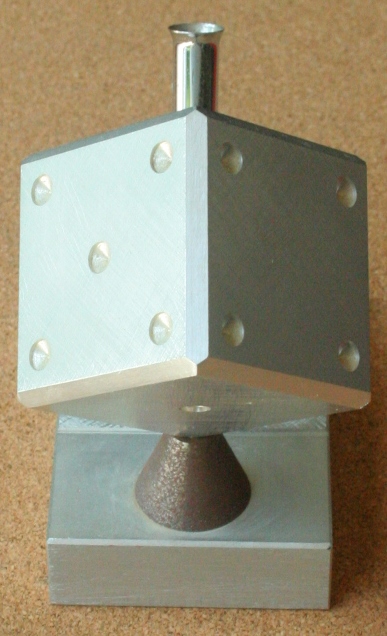
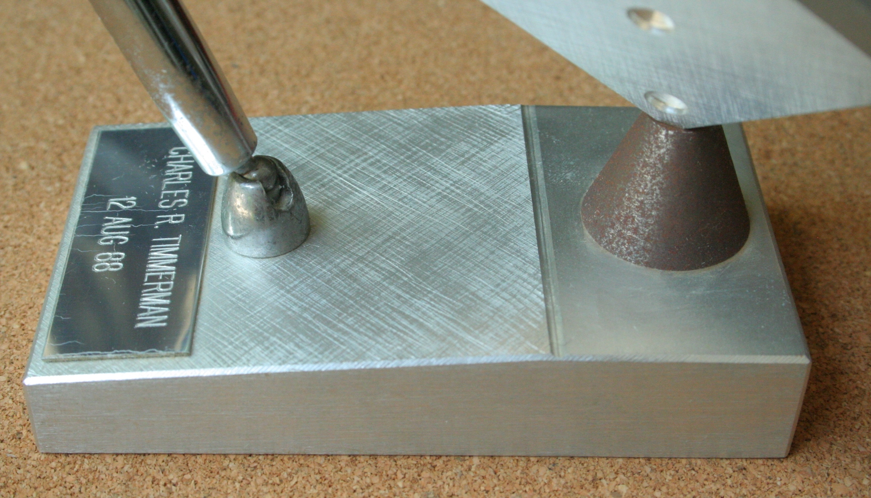
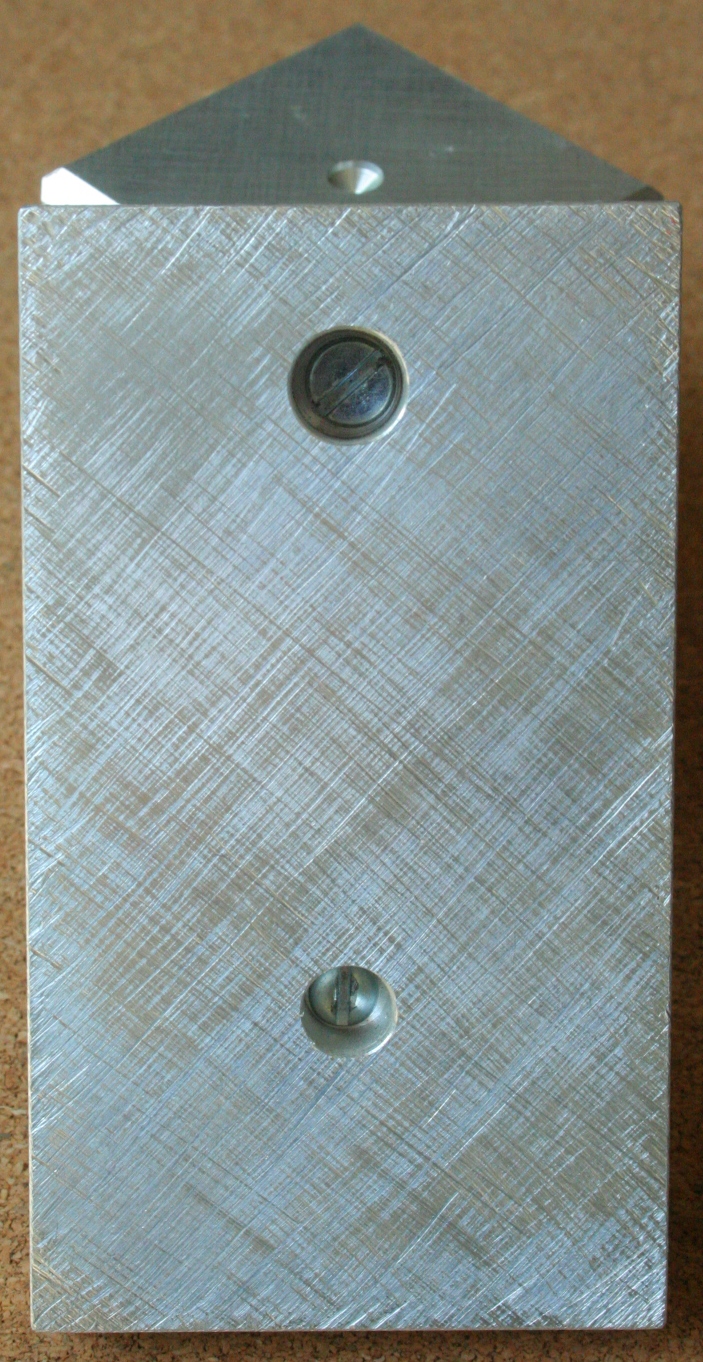
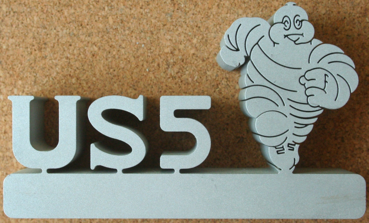
The only tolerance figure I remember is 0.02mm flatness for each face of the cube. This was achieved by holding a small precision square so that the base was held against the face and tilted to approximately 45 degrees. If when held up to the light any light could be seen under the edge of the square then that area was low. By filing away the high areas total flatness could be had. When I finished filing mine I was skeptical (being a natural skeptic) so I checked mine with an indicator on a stand and on a surface plate. Sure enough it was within 0.02mm. The cube is approximately 50mm in diameter. The actual figure wasn't important. They wanted it the same across each pair of faces all the way around. This was achieved by locking a vernier caliper on the dimension of the first two opposite faces. The same amount of resistance when slid along the faces indicated that the dimension was the same. I don't recall how we determined the squareness of one side to the next. The shaper was used to bevel the edges. The base design was up to us, sort of. I don't recall how much was up to us. Mine was draw filed along the sides. I shaped the narrow top ledge on the shaper and filed the ramp flat. I don't recall how the ramp was roughed out. It may have already been done for us. It's been 30 years and some of it is difficult to recall. The pen holder of course was ready made. The Mr. Bib was cut out on a CNC wire EDM machine. They even used it to cut out gears. Amazing. They gave me the Mr. Bib paperweight when I left the company.
Attachment 24939Attachment 24940Attachment 24941
Attachment 24942Attachment 24943
Wow nice work Floradawg,,,I've been by that plant a few times. Mostly buying up tools off craigslist
Excellent craftsmanship and thanks for sharing.
Shame about what looks like rust on the support!
Regards,
Brian