Free 186 More Best Homemade Tools eBook:  
Get 2,000+ tool plans, full site access, and more.

User Tag List

Page 2 of 3 FirstFirst 1 2 3 LastLast
Results 11 to 20 of 21

Thread: Simplifying the measurement of bores

  1. #11
    Supporting Member metric_taper's Avatar
    Join Date
    Mar 2017
    Location
    Marion, Iowa
    Posts
    586
    Thanks
    228
    Thanked 257 Times in 153 Posts

    metric_taper's Tools
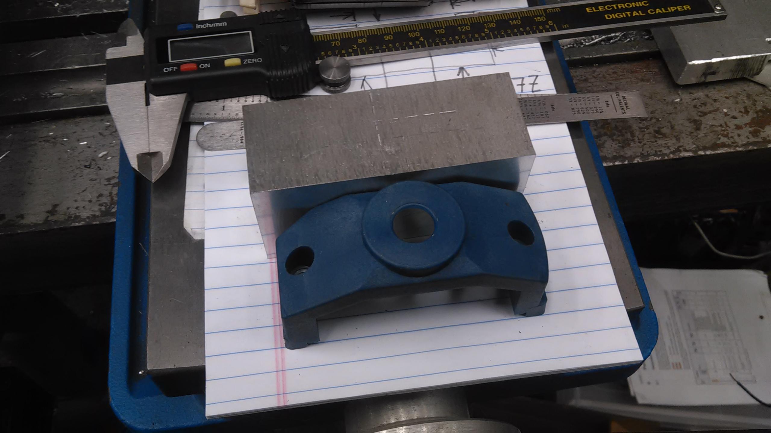
    Thanks Marv. Because of this posting, I purchased an inside micrometer 5mm-30mm. It arrived yesterday. I don't know about it's measurement quality. It was a bit on the cheap side at $22 from a US eBay seller. Specs say's .01mm accuracy, but I'm not seeing that with the friction thimble. And the feel is not something I like. It's almost like the anvils are too compliant as I can get .03mm of indicated variance with my current finger pressure feel.

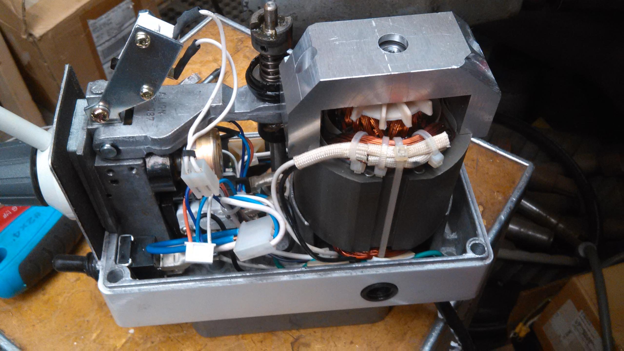
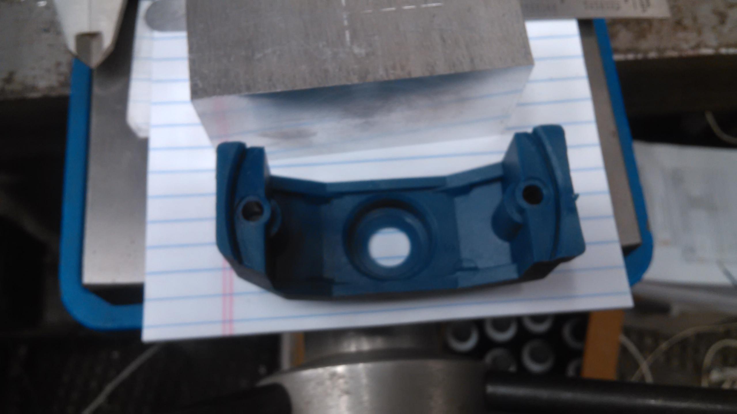
    My need was also part of a project for a 22mm OD ball bearing fitment. Looks like I made an oversize bore of 22.05 (if I trust this micrometer for those that think SAE, that's .002 over), I wanted a slip non press fit. The bearing is on a universal motor that can spin pretty fast, so I hope the bearing does not spin and make shrill noises. It was a boring head operation in the vertical mill, I thought I was sneaking up on it, but overshot. This project is to modify a milling machine table feed to incorporate an encoder speed sensor on the motor shaft. I'm trying to improve the feed speed, as the usable sweet spot on the potentiometer is very narrow. The current method is phase control SCR circuit with no feed back. I just recently fell into the Arduino HOLE, and this seems like a fun project to fix a long term annoyance.

    186 More Best Homemade Tools eBook

  2. #12
    Supporting Member Toolmaker51's Avatar
    Join Date
    Feb 2016
    Location
    Midwest USA
    Posts
    5,333
    Thanks
    7,042
    Thanked 2,981 Times in 1,893 Posts

    Toolmaker51's Tools
    Quote Originally Posted by metric_taper View Post
    Thanks Marv..........oversize bore of 22.05 (if I trust this micrometer for those that think SAE, that's .002 over), I wanted a slip non press fit.
    .002 might ordinarily be a problem, but can be remedied with Loctite [or comparable] Bearing Retainer fluid. I've had great luck with enamel paint used the same way, just brush the bore and bearing wet and install. Wipe away excess. The paint wants to equalize it's film, consequently centering the part. You could bore larger and sleeve with an aluminum ring, but unless .100 thick or more it deforms easily.

    2000 Tool Plans
    Sincerely,
    Toolmaker51
    ...we'll learn more by wandering than searching...

  3. #13
    Supporting Member Frank S's Avatar
    Join Date
    Aug 2015
    Location
    Peacock TX
    Posts
    11,225
    Thanks
    1,986
    Thanked 8,789 Times in 4,207 Posts

    Frank S's Tools
    There are several products on the market like the Permetex liquid steel or shaft seal that are really good for tightening up minor differences of diameters Some of the more expensive 2 part fillers are even certified by Caterpillar for up to .040" on 2" or larger shafts. Belzona was the one I used to use a lot. Once cured it can withstand the beatings of an excavator's use
    Never try to tell me it can't be done
    When I have to paint I use KBS products

  4. The Following User Says Thank You to Frank S For This Useful Post:

    Toolmaker51 (May 6, 2018)

  5. #14
    Supporting Member metric_taper's Avatar
    Join Date
    Mar 2017
    Location
    Marion, Iowa
    Posts
    586
    Thanks
    228
    Thanked 257 Times in 153 Posts

    metric_taper's Tools
    The part is a motor "end bell housing" so it has to be removable. I'm making an aluminum part to replace the plastic original so I can mount the encoder photo optical piece.
    Simplifying the measurement of bores-img_20180506_154951.jpgNew aluminum test fit.
    Simplifying the measurement of bores-img_20180429_161805.jpgPlastic original
    Simplifying the measurement of bores-img_20180429_161750.jpgNote the top does not have a flat boss outside the ball bearing area. Hence the new aluminum part.

    I've thought of making a tool that mounts in my boring head, that will hold a single straight knurl wheel. So I would knurl the inside surface, then somehow do a better job of boring this out. But I'm thinkin .05mm might be OK, I could cheat and use some sort of deformable plastic shim. I just don't want to fight removing the bearing from this support.
    Sorry for highjacking this thread.

  6. The Following User Says Thank You to metric_taper For This Useful Post:

    Toolmaker51 (May 6, 2018)

  7. #15
    Supporting Member Frank S's Avatar
    Join Date
    Aug 2015
    Location
    Peacock TX
    Posts
    11,225
    Thanks
    1,986
    Thanked 8,789 Times in 4,207 Posts

    Frank S's Tools
    For the part you are working on if it is the aluminum end bell that is over bored. I doubt if I would do and knurling on the ID. But you could probably simply stake the bearing in place using a sharp pointed punch around the face of the housing to reduce the diameter
    Never try to tell me it can't be done
    When I have to paint I use KBS products

  8. #16
    Supporting Member
    Join Date
    Aug 2016
    Posts
    635
    Thanks
    1
    Thanked 187 Times in 166 Posts

    wizard69's Tools
    Thanks Marv!

    This highlights yet another reason to get a set of adjustable parallels. The more uses I find for these tools the easier it is to justify the expense.

  9. #17
    Supporting Member metric_taper's Avatar
    Join Date
    Mar 2017
    Location
    Marion, Iowa
    Posts
    586
    Thanks
    228
    Thanked 257 Times in 153 Posts

    metric_taper's Tools
    Frank; I don't want to stake the bearing in, I have to be able to remove this motor armature support bracket. The plastic part is a slip fit, it appears to have been injection molded. Just tight enough to hold the bearing, but removable without excess force. That and there are wavy washers that are installed under the bottom bearing, and this top bearing. These washers are probably not so much for floating the armature, but to enable assembly clearance tolerances. This presses on the outer race, and may keep it from spinning. But I've seen bearings shrill before.
    I used an indicator to set the boring head to what was supposed to be undersize. I did measure the bearing bore with a vernier caliper (guesstimator might be a better name) as I did this before I had the inside mic. I hate starting over on a part, but that may be the correct thing to do. I will assemble it first, mount the encoder parts and see if I can get a signal that can be used for a tachometer feed to either an analog motor speed controller, or a digital one. If the bearing does not spin, I'll just move on.

  10. The Following User Says Thank You to metric_taper For This Useful Post:

    Toolmaker51 (May 6, 2018)

  11. #18
    Supporting Member Frank S's Avatar
    Join Date
    Aug 2015
    Location
    Peacock TX
    Posts
    11,225
    Thanks
    1,986
    Thanked 8,789 Times in 4,207 Posts

    Frank S's Tools
    In lieu of staking I have in past had good success with simple compression. by pressing against both faces of a housing without the bearing being installed My 8 ton arbor press works quite well for slightly compressing aluminum like 6061. The bore will shrink slightly I'm not sure about as much as .002" the most I have tried was .0005 for a .875 bore but it may be worth a shot
    Never try to tell me it can't be done
    When I have to paint I use KBS products

  12. #19
    Supporting Member metric_taper's Avatar
    Join Date
    Mar 2017
    Location
    Marion, Iowa
    Posts
    586
    Thanks
    228
    Thanked 257 Times in 153 Posts

    metric_taper's Tools
    Frank, there is enough material for a set screw to be drilled and tapped. I should have thought of this sooner. And as this is against ball race hard, I won't worry about ending up with a "bite mark" that would make removal difficult.

  13. #20
    Supporting Member Floradawg's Avatar
    Join Date
    Jul 2018
    Location
    Flora, MS
    Posts
    646
    Thanks
    577
    Thanked 131 Times in 98 Posts

    Floradawg's Tools
    I'm getting in on this discussion a little late. I have never trusted telescoping gages for determining the actual size of a bore. Rather I used them to work up to a size and used a go/no go gage to check the finished part. Obviously most of us at our home shop would not have such an item. Your method solves that problem and like a lot of situations, sometimes a staightforward simple idea is the best. Thanks.
    Stupid is forever, ignorance can be fixed.

Thread Information

Users Browsing this Thread

There are currently 1 users browsing this thread. (0 members and 1 guests)

Bookmarks

Posting Permissions

  • You may not post new threads
  • You may not post replies
  • You may not post attachments
  • You may not edit your posts
  •