
 LinkBack URL
 About LinkBacks


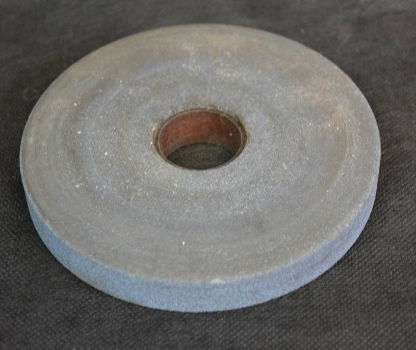
When ever I replace the wheels on any of my bench and arbor grinders which is rare, the first thing I do is true all 3 sides of the wheel.
This aids in getting them balanced also reduces the likely hood that the wheel will have problems later in use life.Helps the grinder to run smoother and quieter.
in my 55 years of being around bench arbor and hand held grinders I can count on 1 hand the incidents I have seen a wheel fail none have ever been from grinding on the sides. I don't make a habit of using the sides of a wheel as the primary cutting surface but when or if the circumstances dictate I will use them.
Where I have seen people have problems in in not keeping their wheels cleanly dressed and grind until they have deep grooves in their wheels usually I see the groves directly associated with the angled "V" grove in the tool rest that so many use as a guide to sharpen their drill bits. I don't like having those made in groves and do not use them most of my bench grinders do not have one. I prefer to free hand and move the drill bit or tooling cutter across the entire face of the grinding wheel. My thickest grinding wheel is 1 " and even at that it does not have a wide enough surface area to sharpen some of my drill bits So I will get the profile as near as possible then finish up on the side or finish up on a belt sander.


 Reply With Quote


 and he could never explain it to me in simple lay terms as you have. My evidence is a box full of inconsistent bits. Now if I can find the time for resesutating 100 bits. "Pin It")


Bookmarks