-
3 Attachment(s)
Tool Post Grinder
I built this little grinder mainly for truing the jaws on my lathe and lathe centers, Maybe some light O.D. & I.D. grinding too.
The grinder has two interchangeable spindles, One for I.D. work which holds mounted stones with 1/4" shanks, The O.D. spindle supports up to a 4" O.D. tool post grinding wheel up to 1/2" wide.
The spindle is supported by two 5202 Double row shielded angular contact bearings rated at 10,000 RPM's. I machined 4 aluminum pulleys to accommodate the proper rpm's for I.D. & O.D. grinding. The I.D. spindle runs at 10,000 rpm while the O.D. spindle runs at 6,000. Changing spindles takes about 3 minutes.
The motor is a Dayton 1/2 HP 10,000 rpm, That I got off e-bay, The bearings were ordered from Mc Master-Carr, The flat belt came from vbeltsupply.com, The hardware came from local suppliers.
The grinder runs very smooth and relatively quiet, It did an excellent job on my lathe jaws, After they were ground I had a .0007" run out, Not to bad for a 3 jaw chuck.
This grinder will fit lathes with a 10" swing and up with the correct spacer
Below are some photos and a couple links to you tube showing the grinder in use.
As always thanks for looking and happy machining
Doug
Click this link to purchase a set of these plans http://www.homemadetools.net/forum/t...er-plans-46306
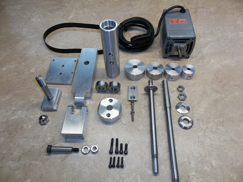
Attachment 7363
All the parts ready for assembly
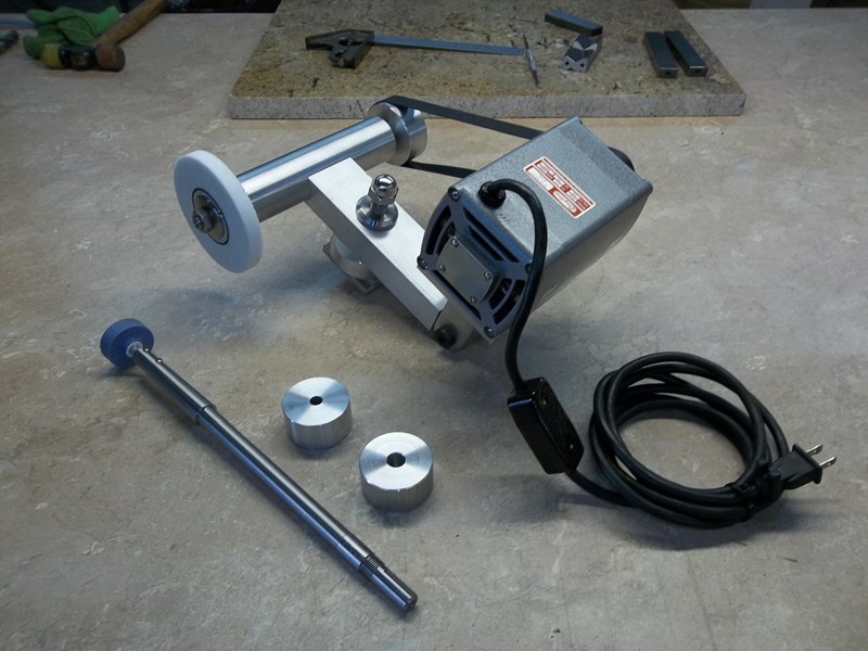
Attachment 7364
External spindle installed
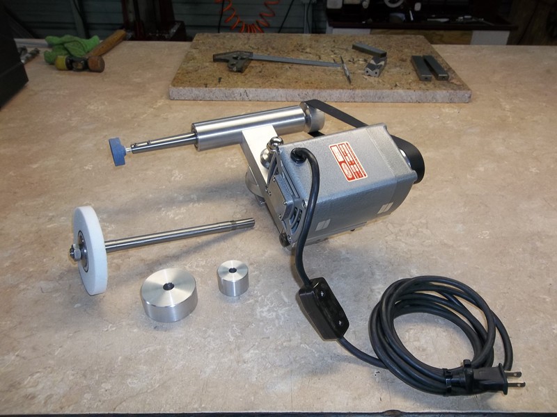
Attachment 7365
Internal spindle installed
https://youtu.be/b5hKySgDVFA
Internal Grinding
https://youtu.be/iXb-niXkiKg
External Grinding
Click this link to purchase a set of these plans http://www.homemadetools.net/forum/t...er-plans-46306
-
Excellent work, and outstanding post!
-
Thanks rossbotics! We've added your Tool Post Grinder to our Grinding category, as well as to your builder page: rossbotics' Homemade Tools. Your receipt:
<div id="blocks">
<div class="block b1 pngfix">
<div class="bimg">
<div>
<a href="http://www.homemadetools.net/tool-post-grinder-16"><img src="http://www.homemadetools.net/uploads/139267/tool-post-grinder-16.jpeg"
/></a></div>
</div>
<div class="head pngfix"></div>
<div class="left pngfix"></div>
<div class="right pngfix"></div>
<div class="blockover b1 pngfix">
<div class="title">
<a href="http://www.homemadetools.net/tool-post-grinder-16">Tool Post Grinder</a>
<span> by <a href="/builder/rossbotics">rossbotics</a></span>
</div>
<div class="tags">tags: <a href="http://www.homemadetools.net/tag/grinder">grinder</a>, <a href="http://www.homemadetools.net/tag/pulley">pulley</a>, <a href="http://www.homemadetools.net/tag/tool-post">tool post</a></div>
</div>
</div>
</div>
-
Doug,
Excellent design and work as usual that shows in all your homemade tools. Thank you for references to the shielded angular contact bearings.
I am curious about your chuck jaw grinding. What method did you use for pre-loading the chuck jaws during your grinding process? I have seen some toolmakers hold a thin washer set into a recess way in the back of the jaws, some have a special clamp that fits over the angular edges of the jaws to hold them taut while others just rely on high speed centrifugal force to hold the jaws under tension. Just curious about your technique.
Thanks for the posting, Paul
-
Super nice, and quiet too. I'm with Paul about the pre-loading? Looked like some kind of 60º wedge braces in the first vid?? Seven tenths really Rocks! Not Bad...LOL! Really terrific docs/write up, with your usual Thoroughness!! The internal spindle washer is a beautiful design. How did you do the .625 radius to match the bore of the spindle? Also curious about the 10k motor and rough price for it...never saw one with that frame style, but looks real handy for mounting. Thanks very much for sharing another of your great build!! ~PJ
-
Thanks PJ's for your compliments
I preloaded the jaws with 3 pieces of 1/2" plywood, I cut them about a 10° angle on each side and placed them against the chuck face, I then just screwed the jaws down until they tightened themselves against the wood pretty snug and ground away, I fed the grinder in and out until there were no sparks ( by power feed of course ).
The .625 Radius was cut with a boring head. I took a scrap piece of aluminum plate and bored a 1.750" hole, There is your radius, I then put the base in the mill vise on it's edge and moved in about .050" at the time and machined it like you were boring a hole. You can figure the rest I'm sure.
The motor is a Dayton, Model # 2M145, I got it new off e- bay I paid $145.00 for it.
Thanks Again Guy
Doug
-
Thanks Paul for your compliments
I preloaded the jaws with 3 pieces of 1/2" plywood, I cut them about a 10° angle on each side and placed them against the chuck face, I then just screwed the jaws down until they tightened themselves against the wood pretty snug and ground away, I fed the grinder in and out until there were no sparks ( by power feed of course ).
Thanks Again
Doug
-
Great work.
However, can you explain how a grinder would be more accurate than a cutter? Won't the grinding wheel wear down changing it accuracy?
Noo-bee machinist, Brian
-
Truly My Pleasure, Doug. I learn a lot from your designs and ways to do things...and sure a lot of others do to. Good idea about the ply will give it a try...not sure I can reach 7 tenths though! :lol:
Still a bit confused about the "Spindle Housing Retaining Washer" and may have been a bit unclear above. I thought about it and thought a simple way would be to take a piece of 1.25 RB or larger, turn to size and then mill the flat and drill the holes and CS's??
Nice deal on the Motor!
Thanks for taking the time! ~PJ
-
Oh PJ"s LOL
I was wondering when someone would ask about how I attached the spindle housing to the base, I left that undocumented just to see if anyone even noticed how that was done, congratulations to you sir.
If you look at these 3 drawings, the base, spindle housing , retaining washer, If you notice the radius on the retaining washer is the same radius as the bore on the spindle housing itself, In other words the washer goes inside the spindle housing, look at the drilled hole layout on the spindle housing, it's the same as the washer, now look at the base drawing where the radius is machined, there are two 1/4 tapped holes in the end of the base, the spindle housing has 2 sets of holes, the smaller set is for attaching the spindle housing to the tube by means of the retaining washer and the larger is for inserting the 2 flat head screws and a hex wrench from the other side.
Bet you can figure it out now
Thanks Buddy
Doug