Free 186 More Best Homemade Tools eBook:  
Get 2,000+ tool plans, full site access, and more.

User Tag List

Page 2 of 4 FirstFirst 1 2 3 4 LastLast
Results 11 to 20 of 33

Thread: Making tachometers and speedometers

  1. #11
    Supporting Member Saltfever's Avatar
    Join Date
    Apr 2012
    Location
    NorCal
    Posts
    355
    Thanks
    391
    Thanked 126 Times in 86 Posts

    Saltfever's Tools
    Oh my goodness, this sounds very interesting! I have been looking for an excuse to learn Arduino-ese for the past few years. Was even thinking about learning Python from my grandson to see if I could do sumptin useful. And, now Tony, of all things, you have cast away ESP32 tech to tempt us with the Arduino world!

    So here is my problem. It is quite difficult to get good resolution on a high revving engine when all the tick marks are crammed into a 270-300 degree clock face. For example, if a shift point is around 9,500-10,000 rpm, usually everything (in my application) below 6,000-7,000 rpm is useless noise. I would love to display only the top 2,500-3,000 rpm in that same 300 degree window with the correspondly wider tick marks giving much better resolution. My apologies to our motorcycle friends for inferring that 10k rpm was a high number.

    Also, Tony, this tacho thread may take on a new life. Maybe its own thread would be suitable? And, THAN YOU for your always creative and interesting ideas.

    186 More Best Homemade Tools eBook
    Last edited by Saltfever; May 21, 2023 at 07:34 PM.

  2. #12
    Supporting Member tonyfoale's Avatar
    Join Date
    Nov 2016
    Location
    Spain
    Posts
    1,566
    Thanks
    690
    Thanked 2,646 Times in 709 Posts

    tonyfoale's Tools
    Quote Originally Posted by Saltfever View Post
    .... And, now Tony, of all things, you have cast away ESP32 tech to tempt us with the Arduino world!
    I used the Arduino Nano in this project because they are small and I had some. Also it is a task that the Arduino can handle with ease. Any new projects will probably be done with an ESP32, an Arduino on steroids.


    Quote Originally Posted by Saltfever View Post
    So here is my problem. It is quite difficult to get good resolution on a high revving engine when all the tick marks are crammed into a 270-300 degree clock face. For example, if a shift point is around 9,500-10,000 rpm, usually everything (in my application) below 6,000-7,000 rpm is useless noise. I would love to display only the top 2,500-3,000 rpm in that same 300 degree window with the correspondly wider tick marks giving much better resolution. My apologies to our motorcycle friends for inferring that 10k rpm was a high number.
    Easy-peasy.

    Quote Originally Posted by Saltfever View Post
    Also, Tony, this tacho thread may take on a new life. Maybe its own thread would be suitable? And, THAN YOU for your always creative and interesting ideas.
    th62 I do not want to hi-jack your bike building thread so would you prefer that I move any additional content to a new thread or keep it here? It is your call.

    2000 Tool Plans

  3. #13
    Supporting Member Saltfever's Avatar
    Join Date
    Apr 2012
    Location
    NorCal
    Posts
    355
    Thanks
    391
    Thanked 126 Times in 86 Posts

    Saltfever's Tools
    I see the Juken X27 is available on Amazon in various quantities. There appears to be a few flavors, like version, serial number, as well. Is there anything we should watch out for? Will you be making a parts list/schematic available? I'll not post again about this until th62 replies.

  4. The Following User Says Thank You to Saltfever For This Useful Post:

    tonyfoale (May 22, 2023)

  5. #14
    Jon
    Jon is online now Jon has agreed the Seller's Terms of Service
    Administrator
    Supporting Member
    Jon's Avatar
    Join Date
    Jan 2012
    Location
    Colorado, USA
    Posts
    25,565
    Thanks
    7,954
    Thanked 38,847 Times in 11,339 Posts
    13 posts split from this thread: 1974 XS/TX650 rebuild

  6. #15
    Supporting Member tonyfoale's Avatar
    Join Date
    Nov 2016
    Location
    Spain
    Posts
    1,566
    Thanks
    690
    Thanked 2,646 Times in 709 Posts

    tonyfoale's Tools
    I have finally got around to drawing the schematic and adding some comments to the Arduino code.
    This can be used as either a speedometer or ignition driven tachometer. The software is commented with what needs changing for the different applications.

    Lets start with the pretty pictures

    Making tachometers and speedometers-tachoschematic.jpg Click for full size

    A wheel sensor, probably Hall effect or other magnetic type could feed 0 to 5 V pulses directly to the Arduino Nano pin 3 but for isolation, level shifting and some noise reduction it is best to use an opto-isolator as shown top right. My original tacho application used a capacitive pickup from a spark plug lead and I used the signal conditioning circuit shown bottom right. I have not tried it yet but I think that might work well with the opto-isolator instead.

    Now for the code, if anyone wants to follow this but is not familiar with loading code into Arduinos then do not ask here. Much more comprehensive advice is available in tutorials and guides on the Arduino website and forums here arduino.cc

    /*----------------------------------------------------------------------
    Adruino firmware to drive an X27.168 instrument stepper motor to use as a tacho or speedometer.
    For a tacho application you can just wrap a few winds of wire around the spark plug lead, or get a signal
    directly from the ignition system. For a speedo you need a wheel revolution sensor such as a Hall effect
    device. See the schematic for more info on this.

    There are three defines in the software which set the calibration for individual requirements

    #define MAXSTEPS 945 // 945 = (315*3)-> 315 deg rotation * 3 steps/deg
    This is a function of the stepper motor which is unlikely to need changing

    #define myRange 940 //940 leaves 5 steps buffer against over revving
    This sets the range that you want to use. Say you only want to have a swing of 270 degrees then
    myRange = 945 x 270/315 = 810. It needs to be an integer less than 940

    #define rpmFactor 3760000 // 1000000 * myrange * (60/RPM)=3760000 at 15,000 rpm
    RPM is the engine or wheel maximum rpm you want. RPM needs to be multiplied by the number of
    pulses per revolution. The value shown is for a maximum of 15,000 rpm on a single cylinder 2 stroke.

    In void loop() there is an "if" which cuts the power to the motor when the rpm is low. This is
    to save battery life when it is powered by a small dedicated battery. When powered by the vehicle
    battery this is not necessary and the whole loop() function can be replaced with the following

    void loop()
    {
    int rpm; // This is not the actual rpm, just the calculated motor position

    rpm = rpmFactor/duration;
    if (rpm > myRange) {rpm = myRange;} //Limits FSD to prevent skipping steps
    stepper.setPosition(rpm);
    stepper.update(); // the motor only moves when you call update
    } /* end of loop() */
    ----------------------------------------------------------------------*/

    #include <SwitecX25.h> //Library to drive X25/27 168 instrument steppers

    // standard X27.168 range 315 degrees at 1/3 degree steps
    #define MAXSTEPS 945 /* 945 = (315*3)-> 315 deg rotation * 3 steps/deg */
    #define myRange 940 //940 leaves 5 steps buffer against over revving
    #define rpmFactor 3760000 // 1000000 * myrange * (60/RPM)=3760000 at 15,000 rpm

    //Create and connect a motor called "stepper" to digital pins 8,9,10,11
    SwitecX25 stepper(MAXSTEPS,8,9,10,11);

    volatile unsigned long duration;
    volatile unsigned long startTime;

    void setup()
    {
    // setup pin 3 as an external interrupt. Input from ignition
    pinMode(3, INPUT) ;
    attachInterrupt (digitalPinToInterrupt(3), GetTiming, RISING);

    setZero(); // Zero stepper needle
    startTime = micros();
    } // end of setup

    void setZero() //Set stepper motor to zero
    {
    stepper.maxVel = 40; // Set slow for zeroing against stops
    stepper.currentStep = 950 ;
    stepper.setPosition(0);
    stepper.updateBlocking() ;
    delay(500); /* To let it settle at zero for 0.5 sec. */
    stepper.maxVel = 2000; // I have no idea how fast it can go, but this is enough
    }// End of setZero

    void GetTiming () // interrupt service routine
    {
    unsigned long endTime;

    endTime = micros();
    duration = endTime - startTime ;
    startTime = endTime;
    } // end of GetTiming

    void loop()
    {
    static int hasSlept = 0 ;
    int rpm; // This is not the actual rpm, just the calculated motor position

    if (duration > 250000) // if < 4 Hz or < 240rpm. Increase number for speedometer use
    {
    hasSlept = 1;
    digitalWrite(8, LOW); // Switch off power to motor to save battery
    digitalWrite(9, LOW);
    digitalWrite(10, LOW);
    digitalWrite(11, LOW);
    }
    else
    {
    if (hasSlept == 1){
    hasSlept = 0;
    setZero();
    startTime = micros();
    }
    rpm = rpmFactor/duration;
    if (rpm > myRange) {rpm = myRange;} //Limits FSD to prevent skipping steps
    stepper.setPosition(rpm);
    stepper.update(); // the motor only moves when you call update
    }
    } // end of loop()

    -------------------------------------------------------

  7. The Following 5 Users Say Thank You to tonyfoale For This Useful Post:

    fizzloid (Jun 15, 2023), freddo4 (Jun 14, 2023), Little Rabbit (Jun 15, 2023), Sleykin (Jun 15, 2023), vasquito (Jun 15, 2023)

  8. #16
    Supporting Member
    Join Date
    May 2022
    Posts
    4
    Thanks
    3
    Thanked 1 Time in 1 Post
    Hello Tony - MANY thanks for your ongoing supply of fascinating and informative posts. Been a fan since I wanted (never got :-( ) one of your frames back in the day :-)
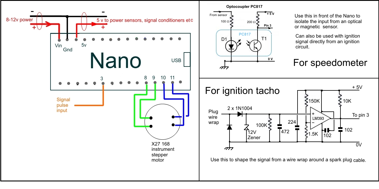
    I'm a bit of a 'Nano' fan - and I've been trying to put together a program to drive shift lights. There are a number already out there - but the various different approaches only serve to confuse (me).
    Having been told in no uncertain terms that my bike racing days are over - these days I amuse myself with little single seaters in hillclimbs and sprints. Never have sufficient time to LOOK at a rev counter - and to be honest can't even see the thing because you're hunkered down so low :-)
    Both cars are relatively high revving - based on Suzuki GSX R600 (K7) and GSX R1000 (K6) the former peaking out at 15K.
    So - the question is:- do you think the approach you have used measuring the duration between ignition pulses via an interrupt is as good as it gets ? And hence applicable to my project too ?
    (600 uses original Suzy electronics, and the 1000 runs a dedicated ECU from MBE)

  9. #17
    Supporting Member tonyfoale's Avatar
    Join Date
    Nov 2016
    Location
    Spain
    Posts
    1,566
    Thanks
    690
    Thanked 2,646 Times in 709 Posts

    tonyfoale's Tools
    Quote Originally Posted by vasquito View Post
    Hello Tony - MANY thanks for your ongoing supply of fascinating and informative posts.

    So - the question is:- do you think the approach you have used measuring the duration between ignition pulses via an interrupt is as good as it gets?
    As good as it gets? That seems a strange question. It drinks pulses synced to a rotary speed and displays an analog scaled representation of the measured frequency. What more do you want? Are you questioning the accuracy. Well it is digital all the way through to the display but then it relies on the accuracy with which the scale was drawn, the alignment of the pointer and our eye's ability to read it. The interrupt will have some latency and there will be the usual +/- count error, but those are smaller than any display/reading errors. There are basically two methods to measure frequency in this context.
    1. Measure the time between pulses, which you question.
    2. Count how many pulses you get in a set time. I used this method around 50 years ago because with the discrete components available then it was the easiest way. However, it tends to give a jerky reading. You can smooth it out by using a very short capture period but then accuracy suffers. A long period gives a jerky meter movement and if acceleration takes place during that period, the reading will be the average over that period and not the value now, so accuracy suffers.

  10. The Following User Says Thank You to tonyfoale For This Useful Post:

    Sleykin (Jun 15, 2023)

  11. #18
    Supporting Member
    Join Date
    May 2022
    Posts
    4
    Thanks
    3
    Thanked 1 Time in 1 Post
    Hi Tony - tricky this electronic text communication isn't it?
    I think that I simply didn't do a good job of asking the question.
    Having reviewed a number of other designs for shift lights, I've seen code written to count pulses and divide by time, to do it twice in order to ignore any spurious results - and several other variations.
    The question I was TRYING to ask ( :-) ) was: do you consider the interrupt method to be the most appropriate and accurate method for measuring pulse frequency ?
    I was NOT querying the accuracy of your implementation - just looking for "reassurance" that this is, indeed, the way to go.
    Obviously the rest of your code doesn't relate to my application, but the two interface suggestions will come in handy as well.
    My thanks again.

  12. #19
    Supporting Member tonyfoale's Avatar
    Join Date
    Nov 2016
    Location
    Spain
    Posts
    1,566
    Thanks
    690
    Thanked 2,646 Times in 709 Posts

    tonyfoale's Tools
    Quote Originally Posted by vasquito View Post
    Hi Tony - tricky this electronic text communication isn't it?
    I think that I simply didn't do a good job of asking the question.
    Having reviewed a number of other designs for shift lights, I've seen code written to count pulses and divide by time, to do it twice in order to ignore any spurious results - and several other variations.
    The question I was TRYING to ask ( :-) ) was: do you consider the interrupt method to be the most appropriate and accurate method for measuring pulse frequency ?
    I was NOT querying the accuracy of your implementation - just looking for "reassurance" that this is, indeed, the way to go.
    Obviously the rest of your code doesn't relate to my application, but the two interface suggestions will come in handy as well.
    My thanks again.
    I think that I answered that with my response labelled "2" in my previous reply. For a shift light you want to know what the RPM is NOW or at least no more than one engine revolution before. Counting pulses in a set time works fine for constant speed or slow acceleration.

  13. The Following User Says Thank You to tonyfoale For This Useful Post:

    Saltfever (Jun 16, 2023)

  14. #20
    Supporting Member
    Join Date
    Aug 2013
    Posts
    1
    Thanks
    0
    Thanked 0 Times in 0 Posts
    I'd be very interested in getting a copy of this PDF and software.
    Thank you

    Bill Whitney
    bwhit5@yahoo.com

Thread Information

Users Browsing this Thread

There are currently 1 users browsing this thread. (0 members and 1 guests)

Bookmarks

Posting Permissions

  • You may not post new threads
  • You may not post replies
  • You may not post attachments
  • You may not edit your posts
  •