
 LinkBack URL
 About LinkBacks


Well part of it might be considered intellectual property I can't show any actual pictures of the controller that I designed simply because I don't have access to them in a failed hard drive LOL I will tell you a little about it though but firstOriginally Posted by metric_taper

your inquiry of the check valves and the distribution manifolds
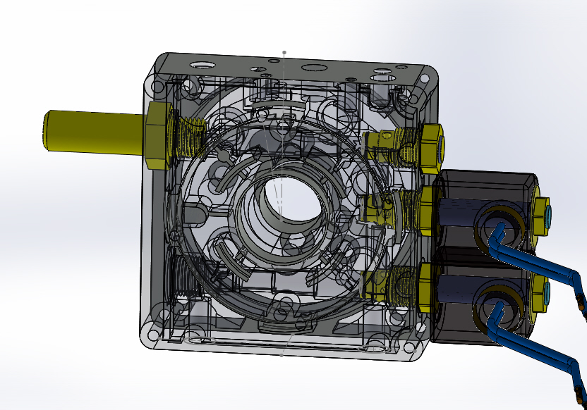
in each pump assembly I designed additional ports and cavity passages into an existing factory mono block motor/ pump adapter block then traveled to the manufacture in Italy a company by the name of Hydronit through a collaboration between their engineers and me we came up with a block that not only suited my needs but extended the usefulness of their products to be used in a wider field of applications. Their blocks already had cavities for check valves relief valves and 2 way solenoid operated poppet valves what my proposal was to make the cavities in the blocks to accept 4 way poppet valves by doing this it opened up a range which would accept flow restrictor valves duel power outputs differential pressure outputs and many other things such as building a multiple pump arrangement.
here is a jpeg of the block It would be most difficult for anyone to duplicate this block from this drawing alone since there are many passages and ports in the block
And yes their block is patented not sure about the changes that I made to them but I should hope they did
Now for the controller basically since my freight elevators were mainly used for 2 to 4 stops the controller to accelerate and slow the platform amounted to a few limit switches and a friction wheel sequential rotary switch. a series of relays and solenoid valves already in the pumps
the operator or person at the door would push the call button a pump would start the platform began to move then that pump would go to full volume the 2nd pump would start with the fluid being briefly diverted a valve would close this would show a brief acceleration the 2nd solenoid would allow that one to go to full volume and the process would be repeated until as many pumps that were dedicated to the unit would all be on line as the platform reached the level going up the pumps would sequentially fall off until full stop. for going down it was a little different as the same valves in the pumps were used but the flow returned through the flow restrictor valves the pumps were not running. there were velocity check valves which would lock down the whole thing in the event of a broken hose. these were located in those manifolds you mentioned this was done to allow the platform to still be raised or lowered even if you removed a hose leading from 1 or more of the pumps, with a main velocity check made into the cylinders in the event of the hose to the cylinder was to burst or was cut intentionally. This did happen once by a guy who thought he could destroy the left by hacking a hose off with an ax. all he managed to do was get oil all over himself and a nice prison stay. `

 Reply With Quote

Bookmarks