
 LinkBack URL
 About LinkBacks


Jon recently highlighted glens5's conversion Mill conversion. Home made "Marvin" attachment
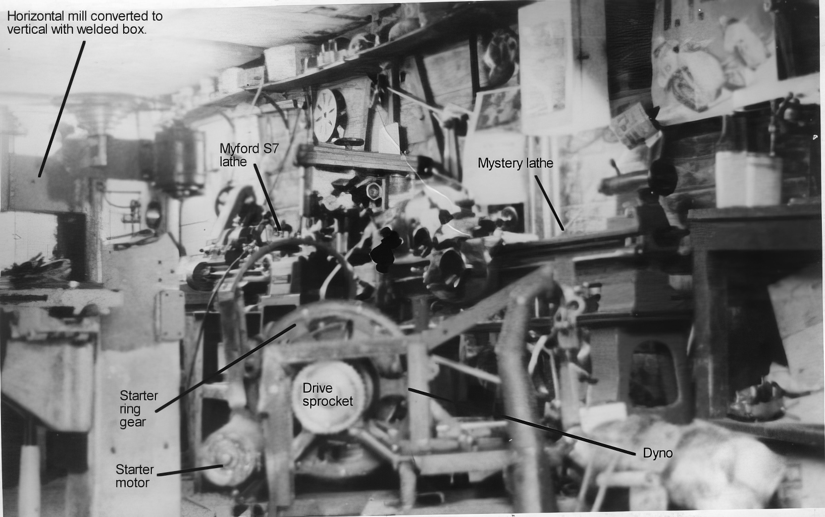
That reminded me of a different conversion that I did over 60 years ago. I used to attend auctions in order to afford tools to build up my workshop. At that time secondhand machinery at auction was often sold at prices that a teenage student could afford. Although I had not even seen a vertical mill at that stage I knew that I wanted one but they never came up at auction, well none that I attended. On the other hand horizontal mills were almost given away. So one day I found myself to be the owner of one. My workshop was a large wooden box that my parents had made for furniture when moving house. It was very crowded with machines and motorcycles and it was a miracle that I could fit the mill in there as well. As the only photo, that I have of it, shows, I managed it.
Click image for full size.
The object of this photo was not the mill but an engine dynamometer that I built from an old torque convertor but the mill can be seen on the left, although only part of the vertical head can be seen.
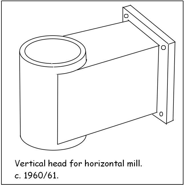
I made a vertical head by welding some 1/2" plate and thick walled tube with a welder that I had made from an old high voltage X-ray transformer core. Although the machining needed was very simple, just face off the back and through bore the tube true to the back, I knew that I did not have suitable tools for that. So I took it to a one man local machine shop where I frequently went to buy material offcuts. There I got to see a vertical mill for the first time, which I studied for as long as permitted. I explained what I wanted done but the man said that he did not have any means to do it. You can imagine the scene as a know-all 16/17 yo tried to tell a seasoned machinist how to do his job. I could not convince him to attempt it so I no choice but to do it myself with what I had. At the time that was a Myford lathe and a drill press. I made a large fly cutter for the lathe and clamped the piece to the cross slide and milled the back. IIRC I had to do it in two positions to reach the length. Not ideal but you do what you have to do. With the back done I reoriented the head, squaring the back off the sides of the cross slide. I made a line boring tool from some 1.5" bar (I would not have remembered the size but I still have it). Halfway along I cross drilled it 1/4" for a HSS tool bit. At one end it was held in a chuck, the other end held by a dead centre. Line boring like this ensures that the bore is parallel along it length. I fitted 75 mm OD taper roller bearing. To locate the bearings axially in this one diameter bore I turned a simple tube which was loctited in place, centered in the bore.
In the absence of detailed photos of the head I just made this sketch which shows it well enough.
I made a spindle with an MT2 socket, the spindle was through drilled so that I could use a draw bar when appropriate. A double stage pulley and belt system gave a large range of spindle speeds.
I would be interested to be able to measure the head today to see just how true I did machine it on that hardworked Myford back then, but I have not seen the machine since 1971. I recall that I did have a surface plate back then but my only measuring instrument would have been a 1" M&W micrometer, which I still have and use. In a twist of irony, lately I have been thinking about how to add a horizontal milling capability to my Bridgeport vertical mill.


 Reply With Quote

Bookmarks