-
7 Attachment(s)
Belt sander stand
Current project is a stand for a belt sander. I got this really cool 2 Kalamazoo belt sander about a year ago. It is a remarkable tool for shaping metal and other materials.
https://www.kalamazooind.com/product...e-belt-sander/
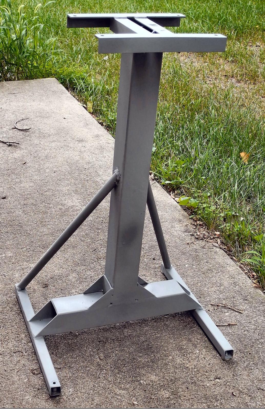
Heres the stand before I mounted the sander:
Attachment 30746
The column and bottom cross piece are 2-1/4 x 2-1/4 x 1/8 square steel tube I had laying around.
It was very rigid side-to-side but not quite rigid front-to-back so I added the diagonal braces. Theyre made out of conduit from Home Depot. That stiffened it right up. Its now solid as a big tree stump.
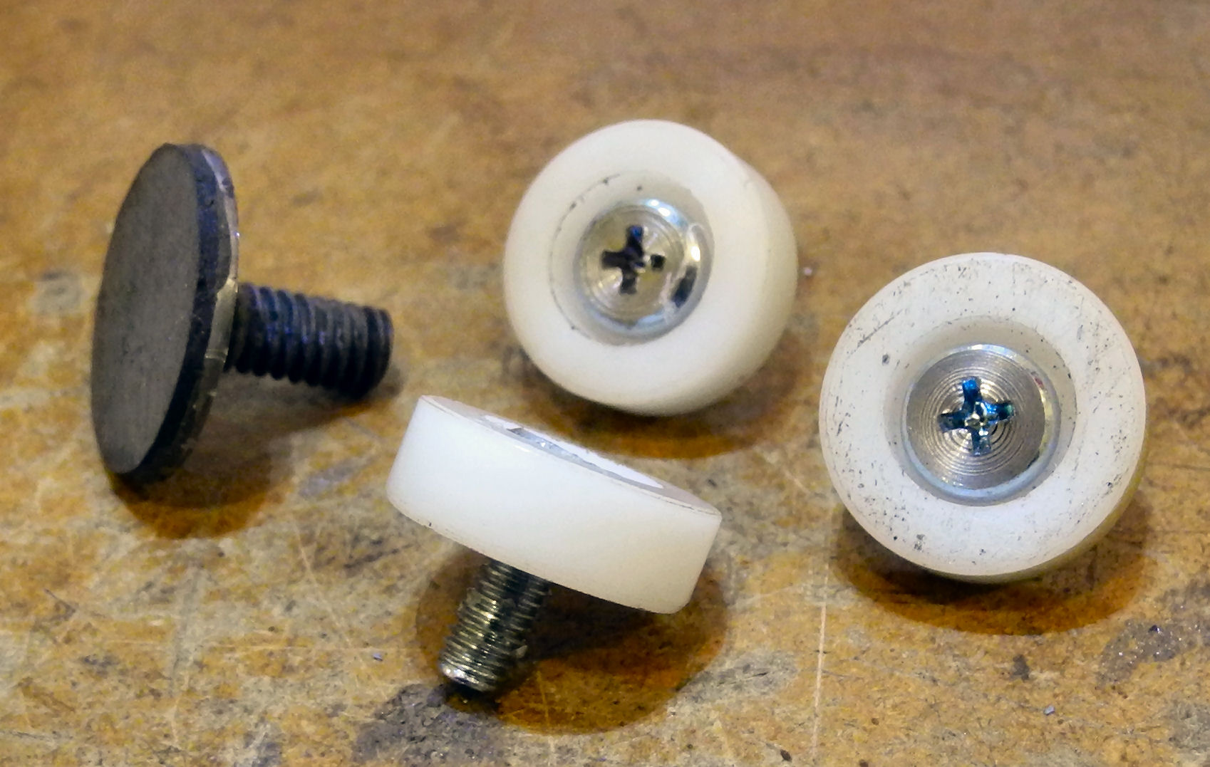
I made little feet for it, 3 fixed feet made of nylon and a fourth with a thin rubber foot that is adjustable to compensate for any irregularities in the floor by screwing it in or out. It fits into a threaded socket that is welded into the foot piece. Its a thin stainless steel disc brazed to a ¼-20 bit of allthread with a rubber disc glued on the bottom.
Attachment 30747
The hardware store didnt have pan head 10-32 machine screws so I grabbed these screws in an ER-25 collet and skinned them down in the lathe.
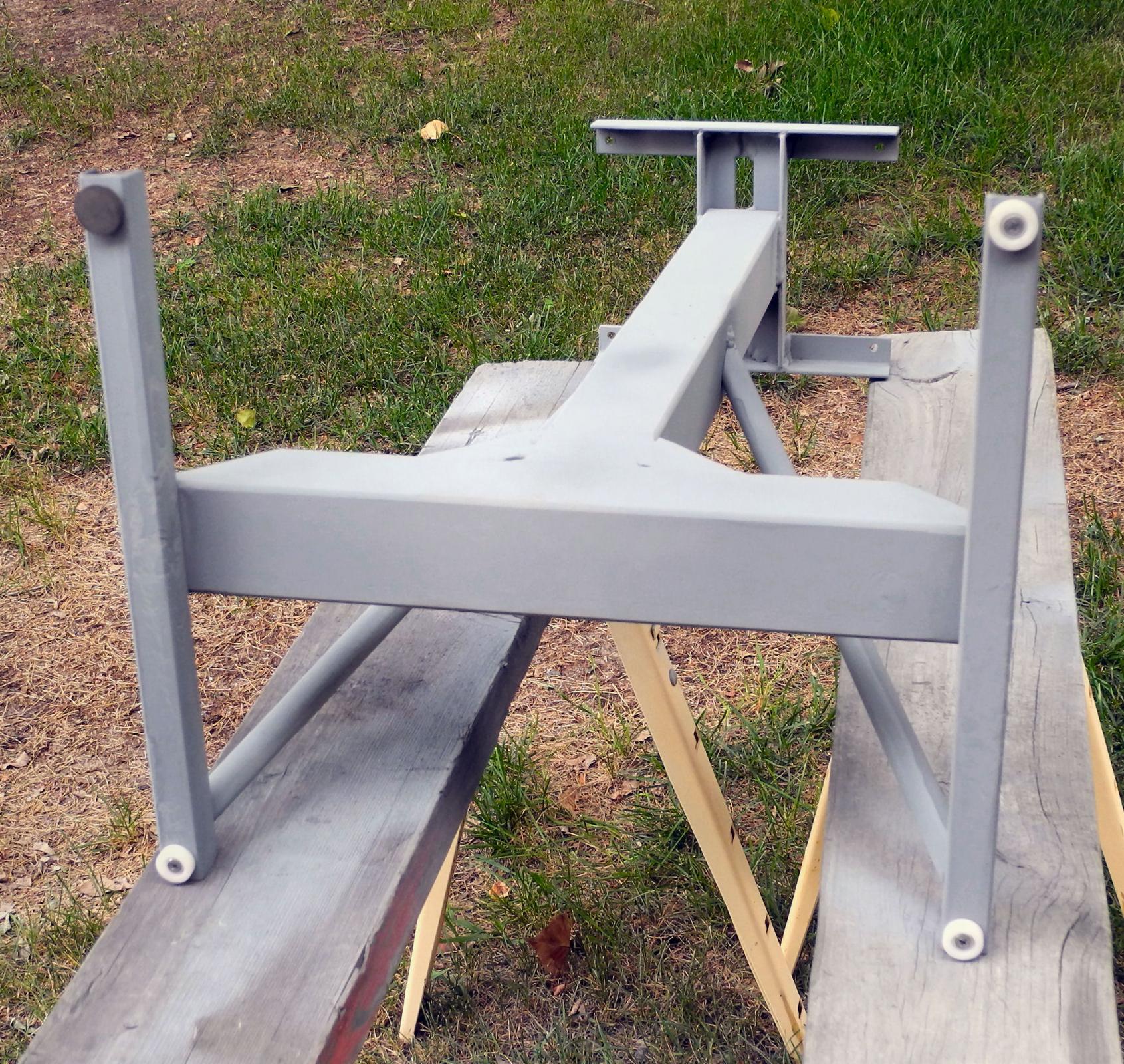
Here they are on the stand:
Attachment 30748
I had to re-make two of the nylon feet after the two that were in place got melted when I welded the braces to the foot members.
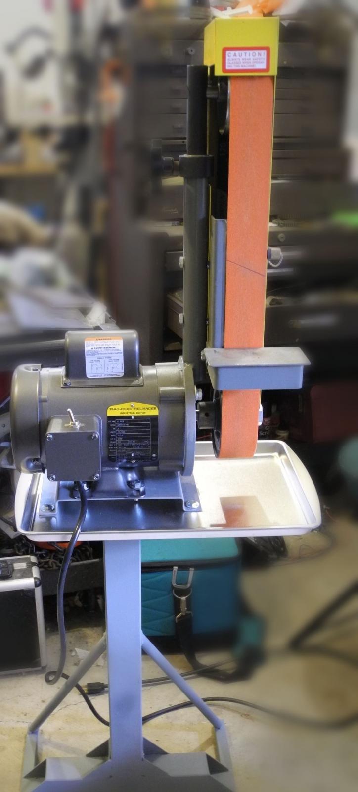
Heres the finished job with sander mounted and ready to go to work.
Attachment 30749
The jelly roll pan came from Target for $1.99. Its to catch dust and grit from sanding/grinding activities.
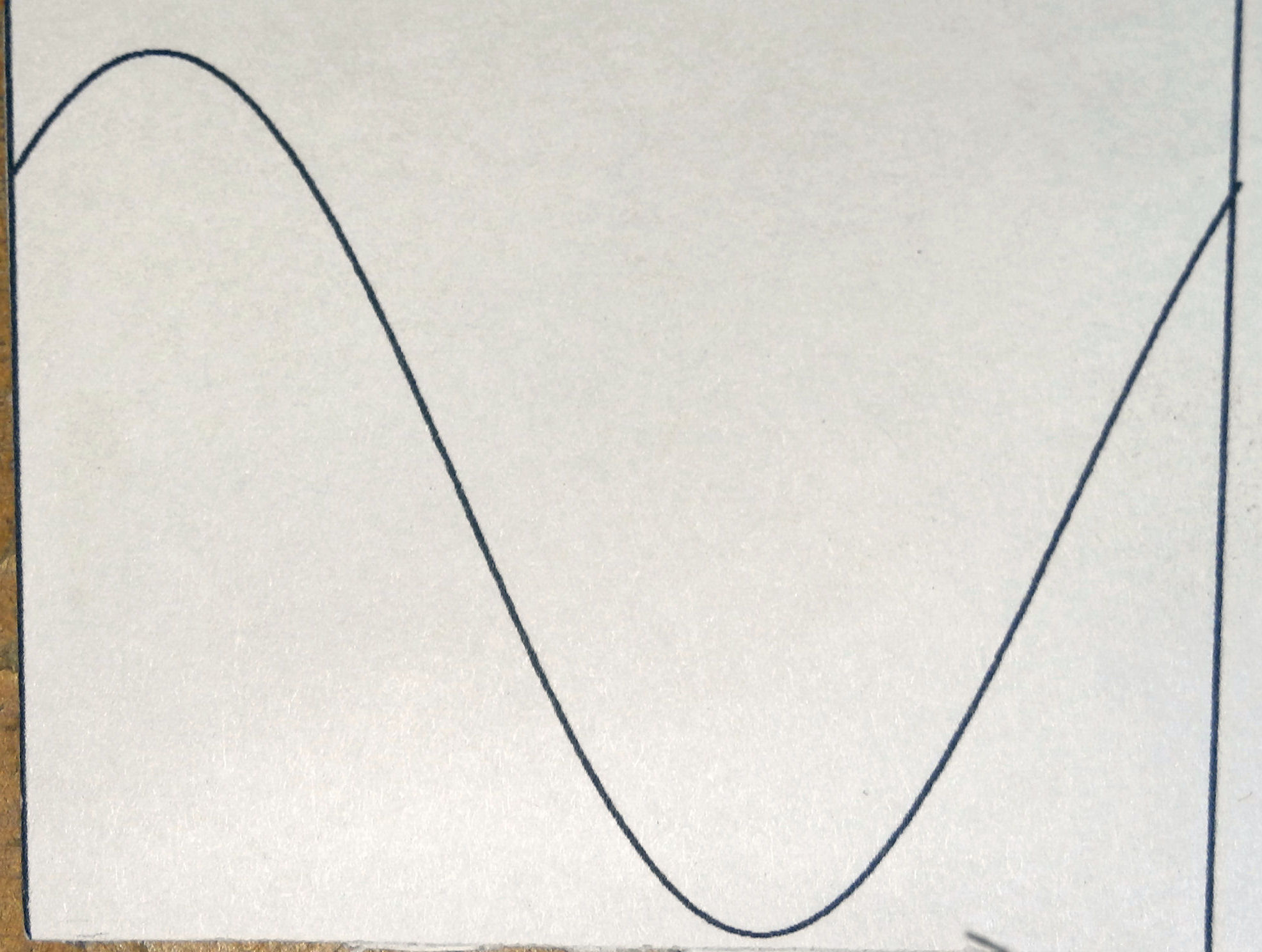
To make the compound angles on the oblique braces I first figured the various angles using 3D modeling and drafting techniques. The smaller bottom angle I just cut with a chop saw that has a miter gage. The top cut is at too steep an angle for the chop saws miter gage (23 degree included angle) and its plane is rotated from the plane of the bottom cut by 46 degrees. I calculated the X-Y coordinates of a pattern which, when rolled around the tube, would present a line to cut to. Then I sent that set of coordinates to AutoCAD to plot the curve on my printer to make a pattern. It looked like this:
Attachment 30750
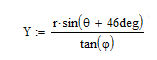
The horizontal X dimension here is circumference of the tube, 360 degrees from left to right. The plot is the locus of the cut line described by
Attachment 30752
where Y is the vertical position of the locus, is 23.2 degrees, the angle of the cut, r is the radius of the tube and is angle of rotation around the tube. The 46 degrees is the angle of rotation between the planes of the two diagonal cuts.
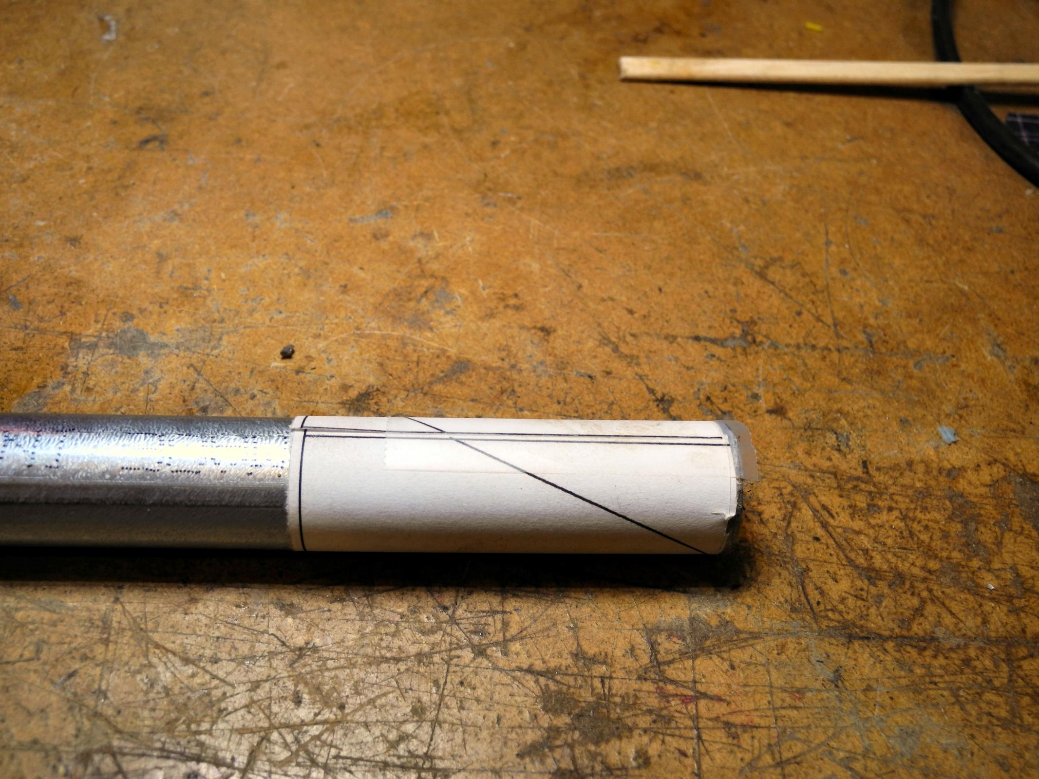
Here the pattern is rolled around the tube and taped in place with the vertical line aligned with the tubes axis:
Attachment 30751
As you can see, when wrapped around the right diameter cylinder it looks like the diagonal cut I needed to make. I then cut to the line with my band saw and then gave them a quick touch on the belt sander to clean them up. Then I welded them to the stand.
-
<!-- BEGIN /var/www/html/homemadetools/protected/modules/zeus/views/tool/postUpdate.php -->
Thanks Don42! We've added your Belt Sander Stand to our Dollies and Stands category,
as well as to your builder page: Don42's Homemade Tools. Your receipt:
<div id="blocks">
<div class="block b1 pngfix">
<div class="bimg">
<div>
<a href="https://www.homemadetools.net/homemade-belt-sander-stand-3">
<img src="/uploads/225868/homemade-belt-sander-stand-3.jpeg"/>
</a>
</div>
</div>
<div class="head pngfix"></div>
<div class="left pngfix"></div>
<div class="right pngfix"></div>
<div class="blockover b1 pngfix">
<div class="title">
<a href="https://www.homemadetools.net/homemade-belt-sander-stand-3">Belt Sander Stand</a>
<span> by <a href="https://www.homemadetools.net/builder/Don42">Don42</a></span>
</div>
<div class="tags">tags:
<a href='https://www.homemadetools.net/tag/belt-sander'>belt sander</a>, <a href='https://www.homemadetools.net/tag/stand'>stand</a> </div>
</div>
</div>
</div>
<!-- END /var/www/html/homemadetools/protected/modules/zeus/views/tool/postUpdate.php -->