
 LinkBack URL
 About LinkBacks


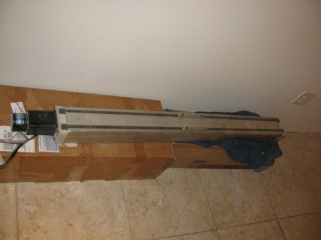
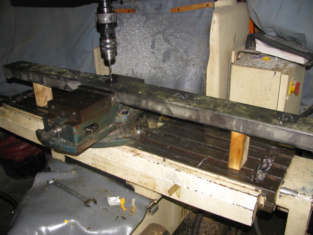
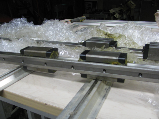
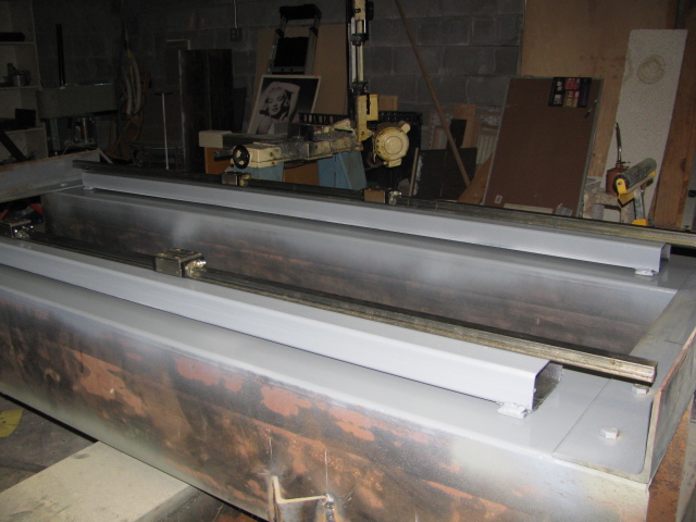
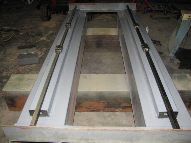
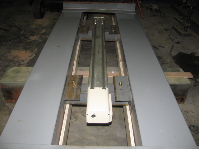
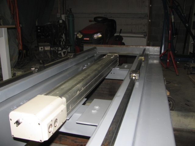
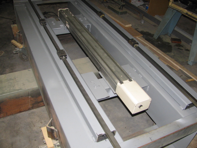
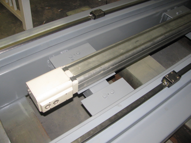
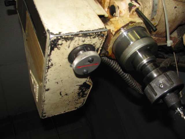
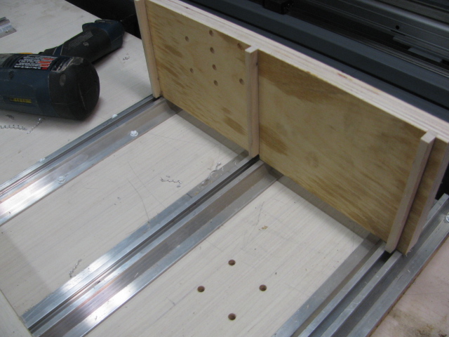
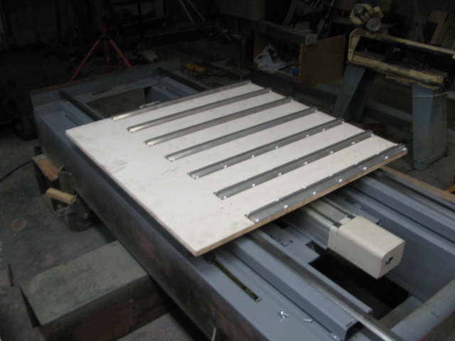
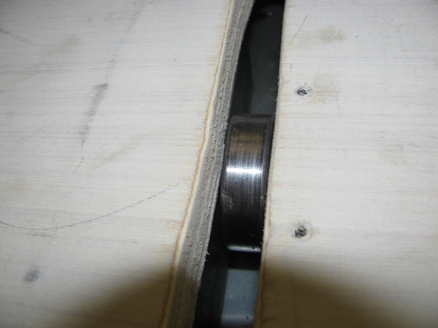
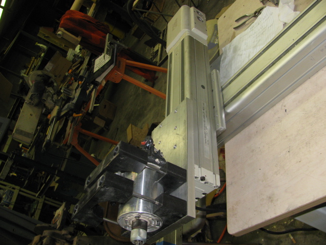
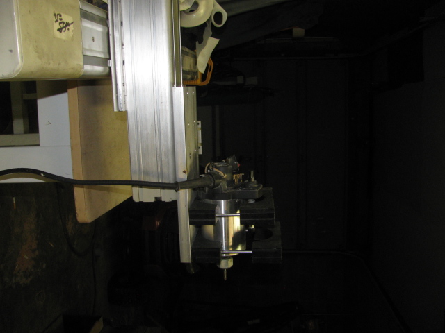
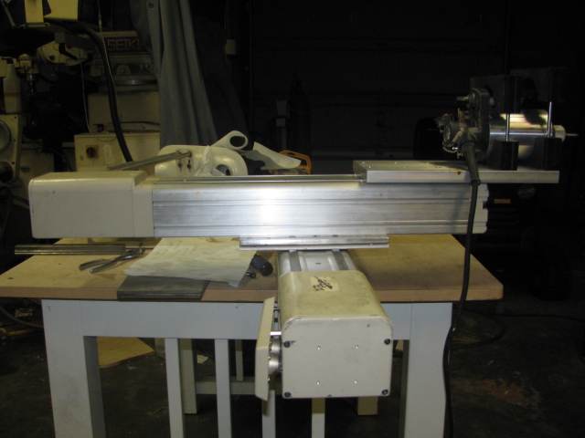
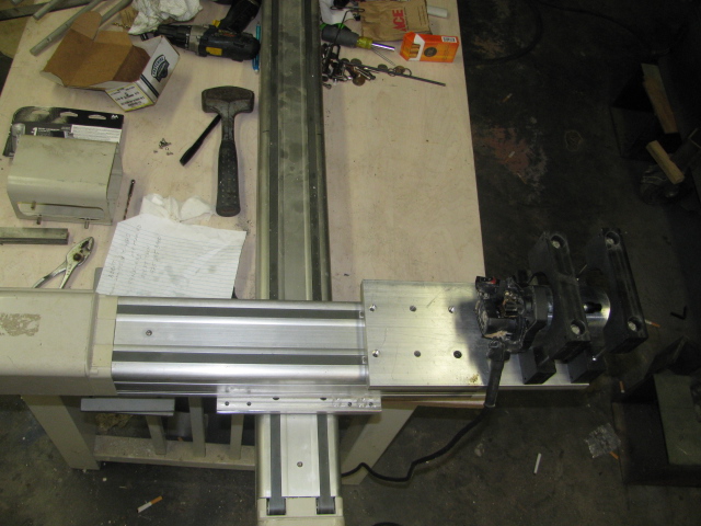
About 5 years back, I started a cnc router build based on Adept robotic arms. I chose this route because the slides, ballscrews and servo motor are all installed in the assembly. I will use three of these slides for x,y,and z. Most of the components are already designed and ready to be installed and or welded. I bought 10 by 10 steel tubing as the base because I got a good price on it. Also the Adept slides are designed with quite a high ballscrew pitch, 20mm., so with that available speed of movement, I elected to build a rigid base. This build will take a while, even though I will be working on it everyday until finished, so I will add some meaningful comments and pictures as the build goes forward. Here are some pictures of the X axis slides and installation. This will be a fixed gantry type router and the table will move 19 inches plus and minus for a movement of 38 inches, both on the X and Y. I am primarily designing this router because I needed an X movement of at least 32 inches to build molds for my 1:32 model train molds. My mill would only traverse 28 inches. I added a pic. of one of the Adept slides. Bob.


 Reply With Quote
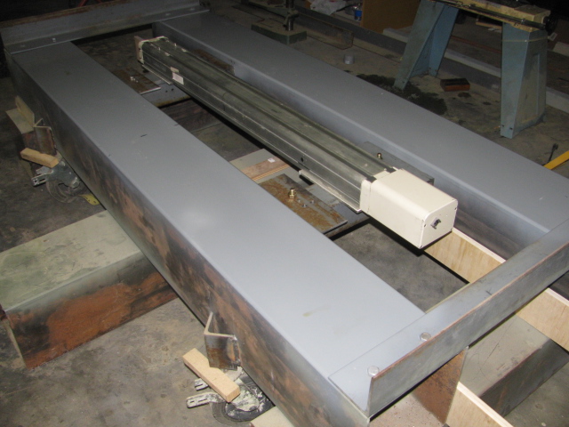


Bookmarks