
 LinkBack URL
 About LinkBacks


I have been wanting a foundry in my shop for a long time. I had one
in the shop where I was teaching for 30 years and miss the functionality
one provides. This post will address the furnace structure. I investigated
the terms Furnace vs Oven. The best explanation I found here;
https://kindle-tech.com/faqs/what-is...rnace-and-oven .
In a nut shell, the main difference is the temperature range, and there is some overlap.
I investigated fuel options; wood, coal, gas, electric, and construction options;
pit in the ground, outside above ground, free standing portable. After experimenting
with various propane burners they are loud, temperature is not easily controlled and propane is not cheap.
I finally settled on a freestanding electric model which could be used inside or moved outside.
Two major deciding factors was the ease of temperature control with electric and the collection
of items I have collected over they years. (Have to start using those things before . I am too old to use them!)
I have read most of the threads on homemadetools.net for inspiration, and give credit
to the many that have done this before. The most recent is;
Heat Treatment Oven (with separate control cabinet)
While Dr Als control box is much more sophisticated then mine, I got still some ideas from that. I will
address my control box in a separate post. I am still refining things.
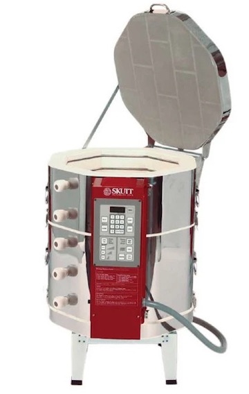
Design was influenced considerably by items that I have been collecting over the years with
an eventual foundry in mind. The most influential component was the fire brick from an old
ceramic kiln. Similar to this one. The one shown is an octagon.
The kiln I got parts from was a decagon.
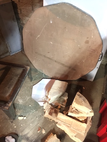
The parts I have are from the art department where I taught.
It had been over fired, declared unsafe for use in the in the
school and discarded. I could not resist taking it home. I was
only able to rescue the top, the bottom, and one section. The
rest was trashed before I got to them.
Top, and remnants of the bottom after I cut it
up to make a top and bottom for the furnace.
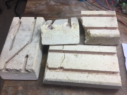
Each section of the original was built from 20 bricks.
Each brick 2 1/2 x 4 1/2 x 9. Many of the bricks were
broken but I was able to salvage a enough good pieces
to make what I needed and have a few extras left.
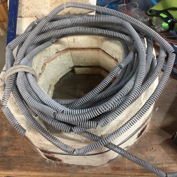
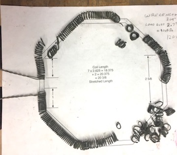
There were 2 - 14 ft heating elements coiled with 14 gauge
Kanthal wire. The coils were too brittle to reshape. Also the
wire is to large a gauge to use in my small furnace. But I will
save it anyway in case I can learn how to anneal it.
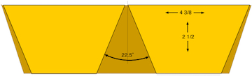
One original brick, 2 1/2 x 4 1/2 x 9 yielded
two 2 1/2 x 4 3/8 x 4 1/2 segments.
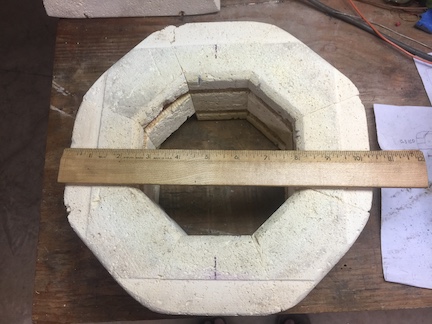
Eight segments were assembled into one octagon
layer. The segments are held together by stainless
steel hose clamps. Two of those octagons provide a
chamber 5 1/2 diameter by 9 high which will
accommodate a piece of 4 schedule 40 steel pipe
for the crucible. (from my junk collection)
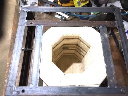
To hold the sections together and attach a lid, 1/16 x 1 x 1 steel
angle was used to build a framework. I collected this material
from the trash behind Tractor Supply. There is 3 of air space
around the heat chamber to provide space for loose pearlite
insulation if necessary.
The top section is held in place by a frame inside a larger
external frame. The top of the brick is relieved so the brick
is flush with the steel.
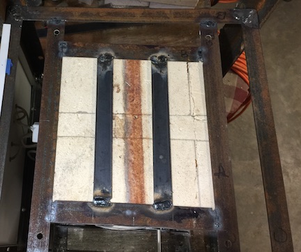
The bricks for the top and bottom where salvaged
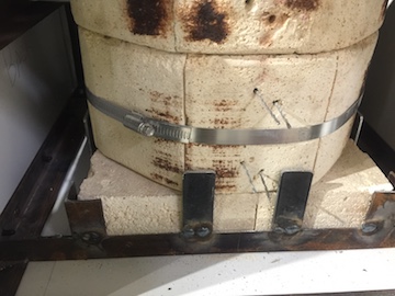
from the bottom of the donor kiln. The bottom frame is
similar to the top with reinforcing bars added
to support the fragile brick and weight of the filled crucible.
The bottom section just sets on the bottom bricks,
it is held in place by tabs welded to the bottom frame.
Also notice the element ends through holes in the brick.
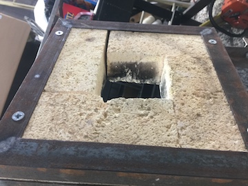
The lid has a hole to vent fumes when necessary,
allow adding material, adding flux and skimming
the melted metal. The top half of the lid frame is
extended to provide a hinge point for the lid. The
screws that hold the lid sandwich together also
hold eye bolts for handles.
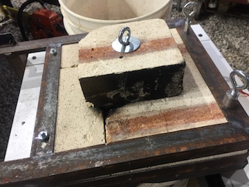
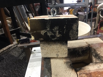
The lid plug is two pieces of brick held together
with an eye bolt. The black is soot from the burning
of paint from the aluminum cans I melted during
the first test firing.
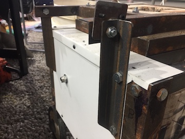
The two frames are held together with 4 flathead
machine screws. The screws are set flush with the
bottom of the frame.
The ends of top lid frame extend to the rear
to meet uprights for hinge points.
When the lid is open, a plate on each side with 2 machine
screws for pins hold the lid up and prevent it from falling
backward when open.
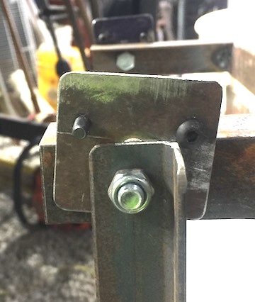
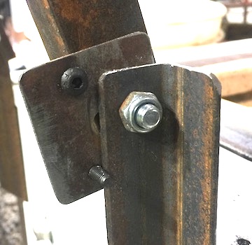
The backside of the furnace is reinforced with a
crossbar that supports uprights for the hinges
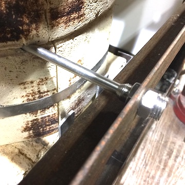
and the thermocouple probe.
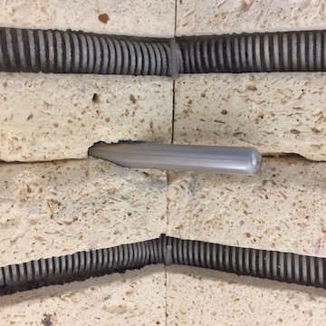
The probe slides through a groove between the
two layers of firebrick. I am not certain this is
the optimum place, but there are not many options.
Time will tell.
The crossbar is hidden by back panel.
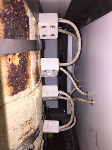
The high temperature connections are made
with ceramic junction blocks. The 4 individual elements
are wired in 2 pairs of 2. (This turned out to not be a good idea.)
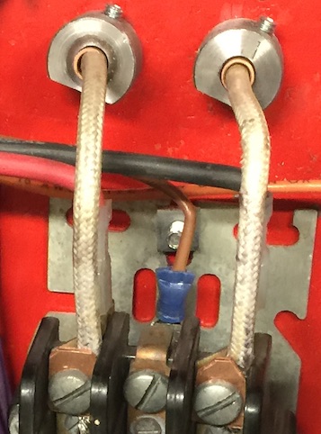
The high temperature wire passes through the sheet metal panel
in a smooth flared copper tube.
The copper tubes are secured inside the control box with
sleeves and set screws. The fiberglass insulation
is tough but frays easily when stripping for connections.
A drop of super glue massaged into the insulation
before cutting and stripping solves that issue.
USE GLOVES for that.
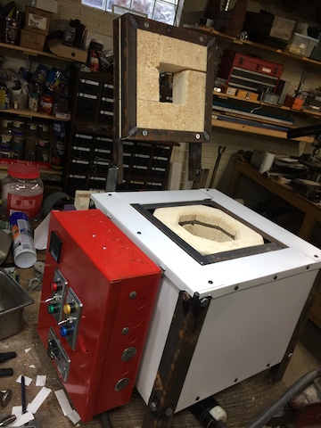
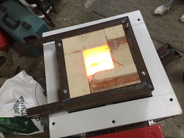
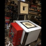
The completed furnace ready for testing. Plans were
to have the control box separate, out of the way of hot
processes. When attached to the furnace, the controller
is too low for my old eyes to get a good view and
to access the buttons for adjustment. But I did not have
the components to make it remote, so I mounted it on the furnace
to allow testing things.
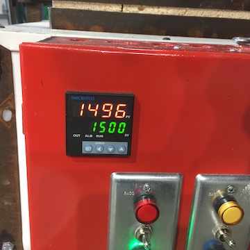
Initial testing went ok. Everything worked. It took
me a little time to figure out the programming on
the InkBird ITC-106VH PID controller. But after my
fat fingers learned with each button was for things
went smoothly.
It soon became apparent that I had pushed the
limits of the heating elements too far. While the
furnace heated up quickly the elements were
getting too hot. You can tell by the color that the
elements are much hotter than indicated on the
controller. The sensor is not able keep up with the
temperature of the element itself.
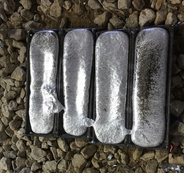
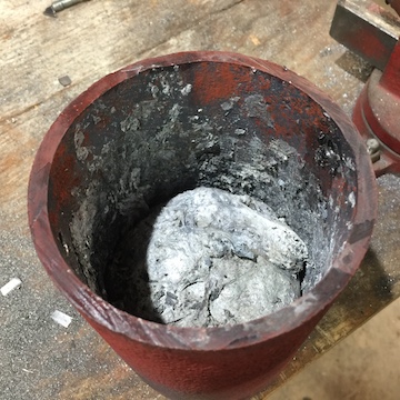
I was able to melt some pop cans on the low setting
which is 1440 watts. This kept the elements cooler but
was VERY SLOW reaching temperature and recovering
when adding more metal to the crucible.
And cast some ingots
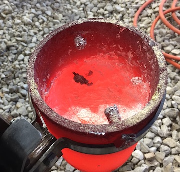
After the first melt, knowing I was going to have to
remake the elements anyway I started another melt
on the high setting, 5760 watts. This worked very well
for a while. But soon the elements began to burn out.
Leaving me with this.
And this.
Currently waiting for new element wire to arrive.
I will update and provide controller information soon.
Other threads related to this;
Easy Follow Rest
Welding Chill Plates


 Reply With Quote


Bookmarks