
 LinkBack URL
 About LinkBacks

I wanted to make an external stock stop for my mini mill. My design was inspired by / adapted from a project in a book (details below).
I thought it would be a good idea to make removable magnetic feet to hold the stop in place on the chuck if desired.
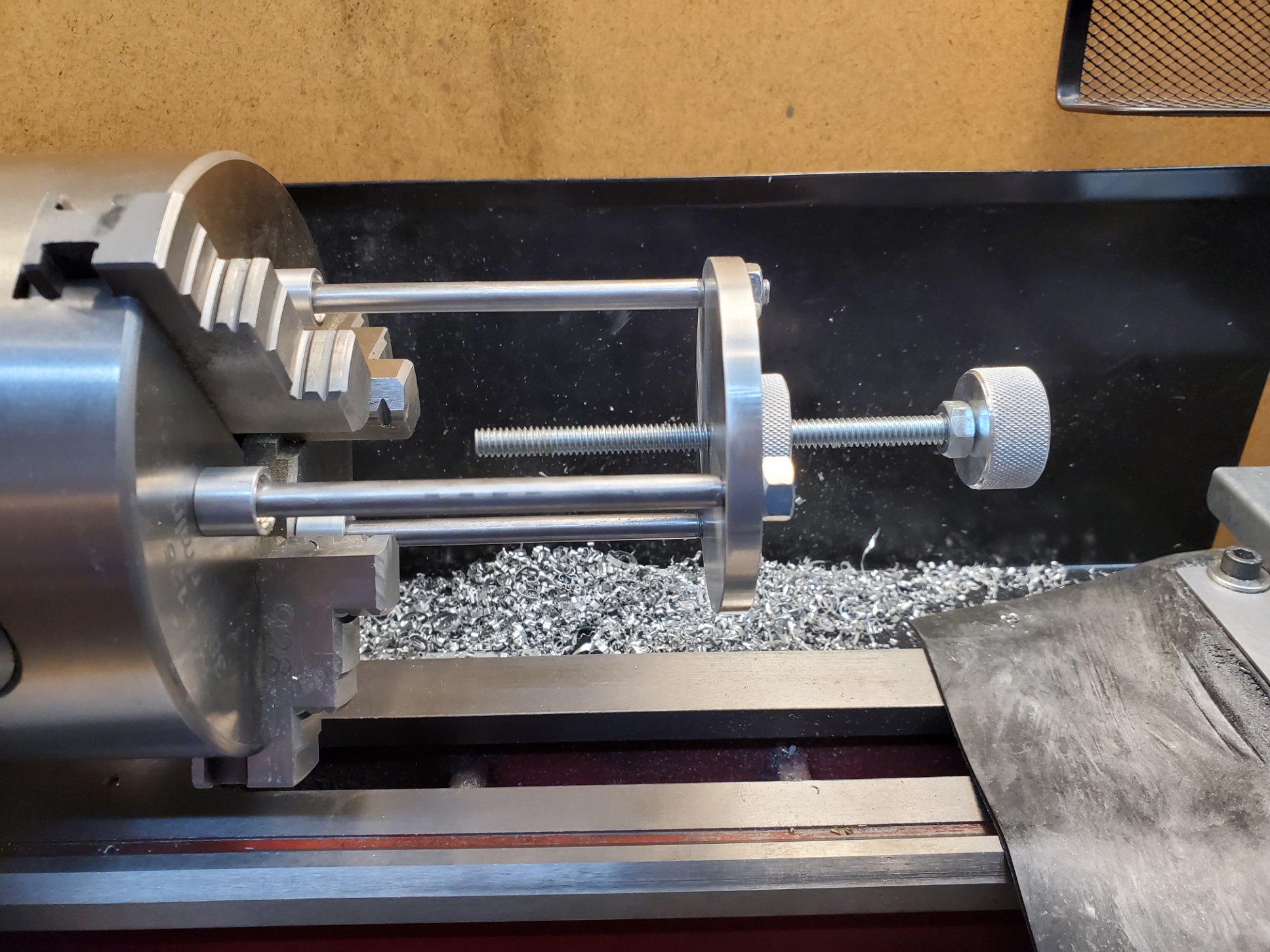
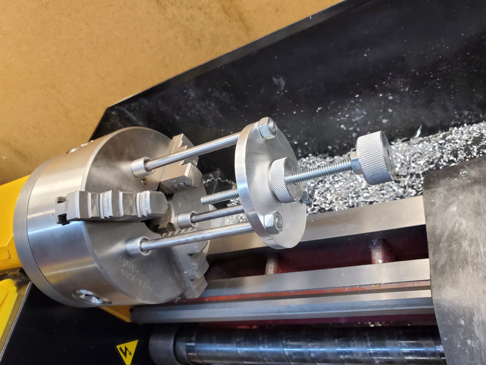
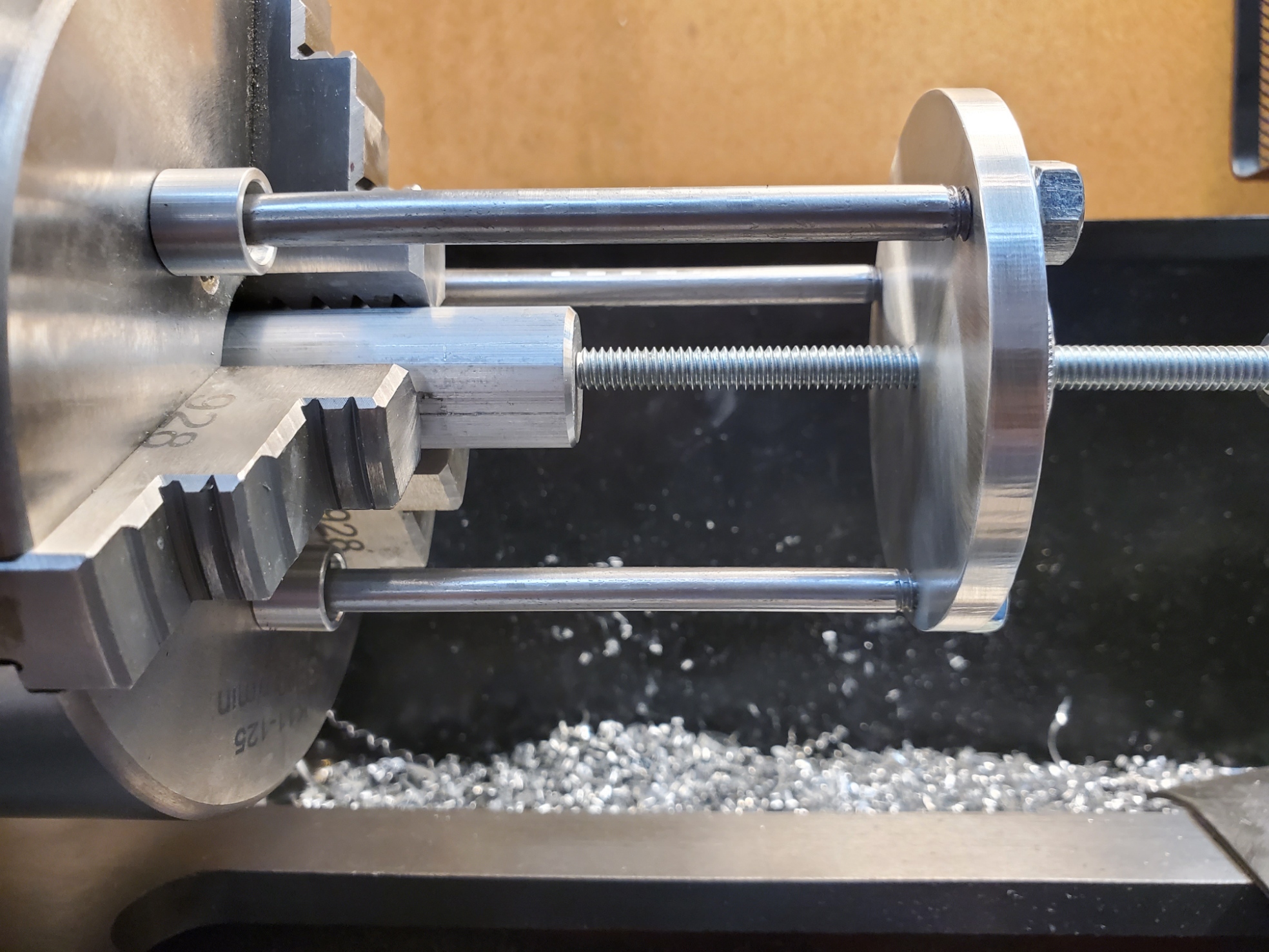
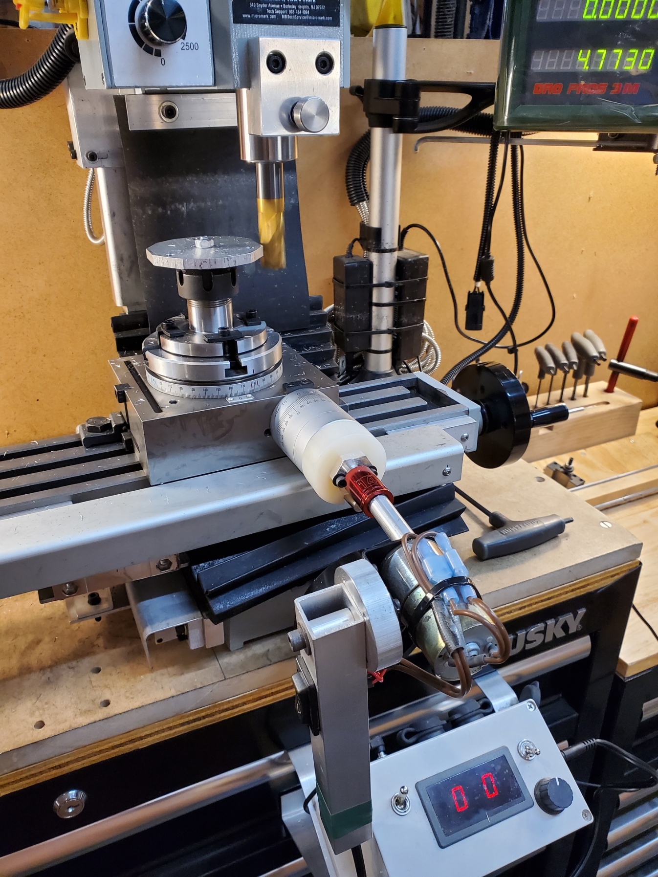
Here are some pictures of the stop in use on my 5" lathe chuck. The knob on the end is used to adjust the stop rod, while the knob in the middle is used as a jam nut to secure the stop rod in position.


When attached to the lathe chuck using the magnets, one leg of the tool should be positioned at or near the bottom and the other two above center as shown. This is to minimize the chance of the tool pulling the magnets off of the chuck.
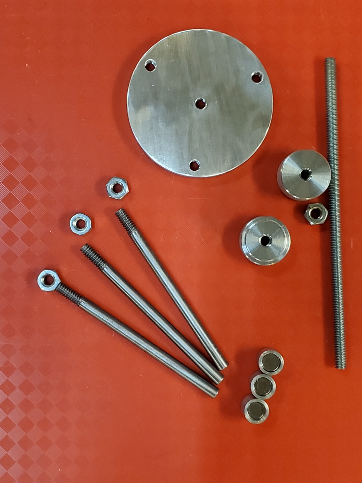
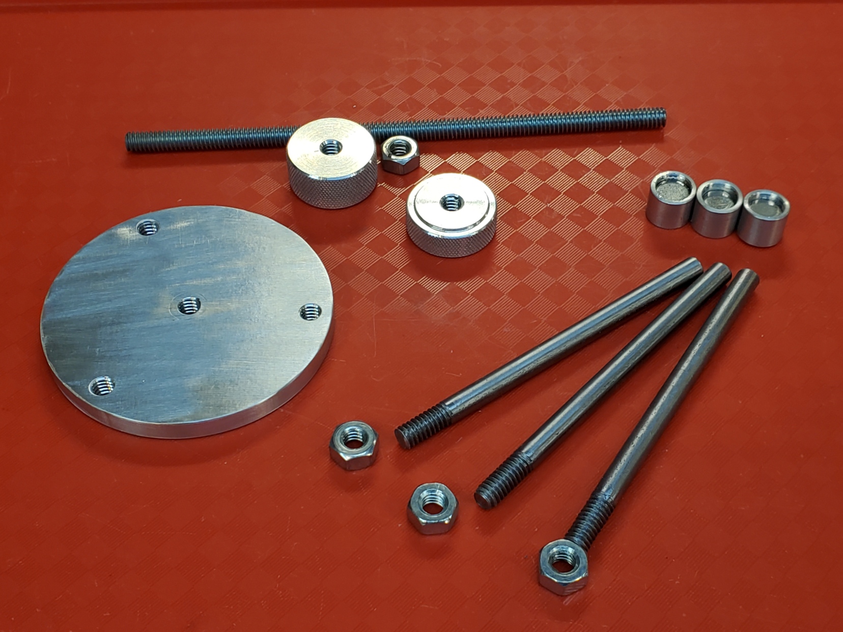
Here are some pictures of the parts prior to assembly.

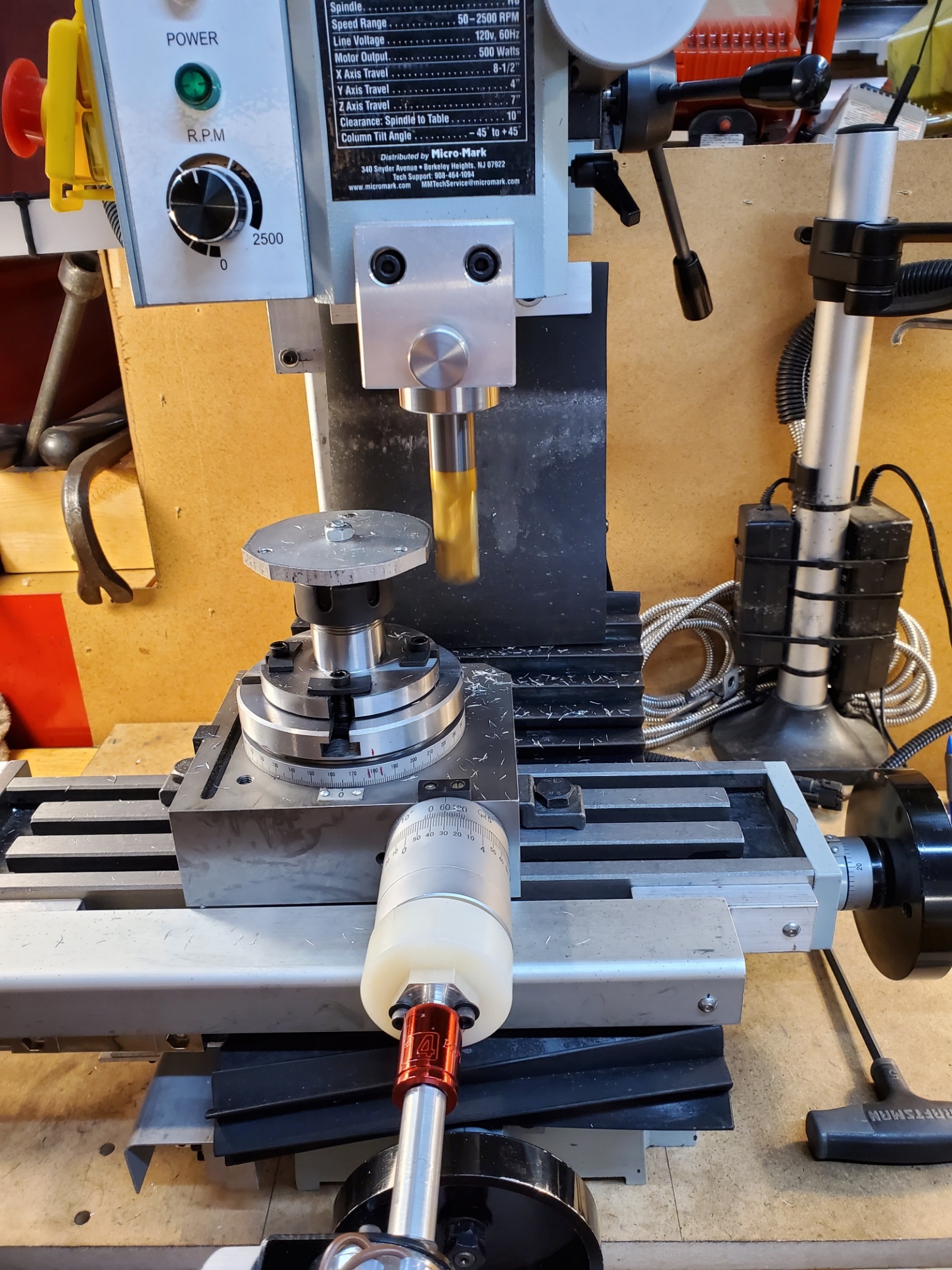
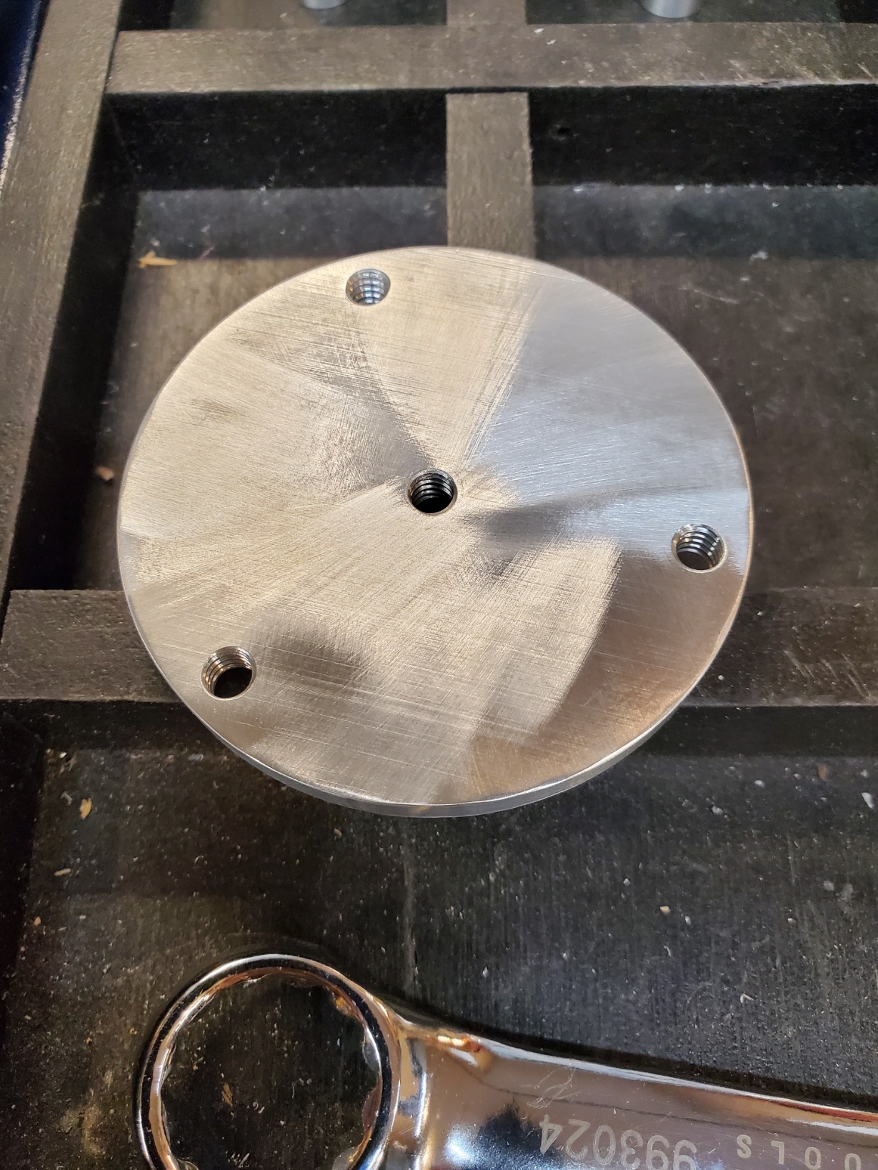
The main body is made from aluminum flat plate. First, I drilled and tapped the 4 holes in the plate. Then I rough cut it on the band saw and rounded it on the mini mill using a rotary table and my power feed. I could have done this on the lathe instead of the rotary table, though I try to avoid interrupted cuts when I can.

I made the body as large as I could and still have it fit the smallest lathe chuck I have (3").
The 3 legs are made from 1/4" drill rod, threaded a short distance on one end.
The two knobs are made from aluminum round stock and knurled on the mini lathe. The stop rod is 1/4" threaded rod, cut to length on the mini lathe and deburred. Common nuts were used to secure the drive knob to the stop rod, and to secure the legs to the body.
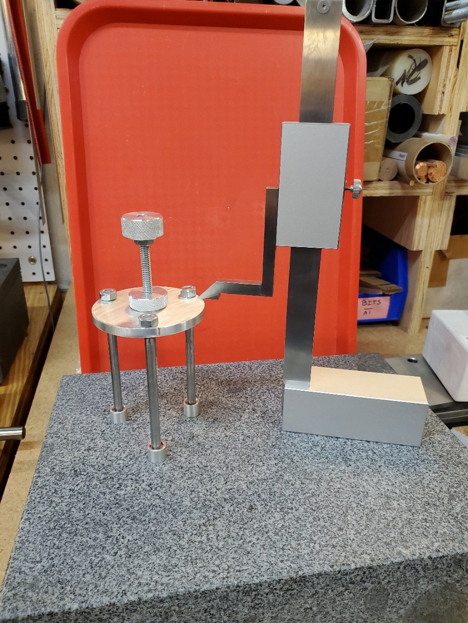
Here is a picture of the assembly process. I used a height gauge and a granite plate to make sure the legs are the same length.
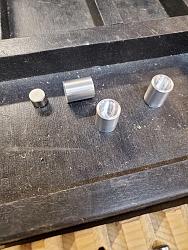
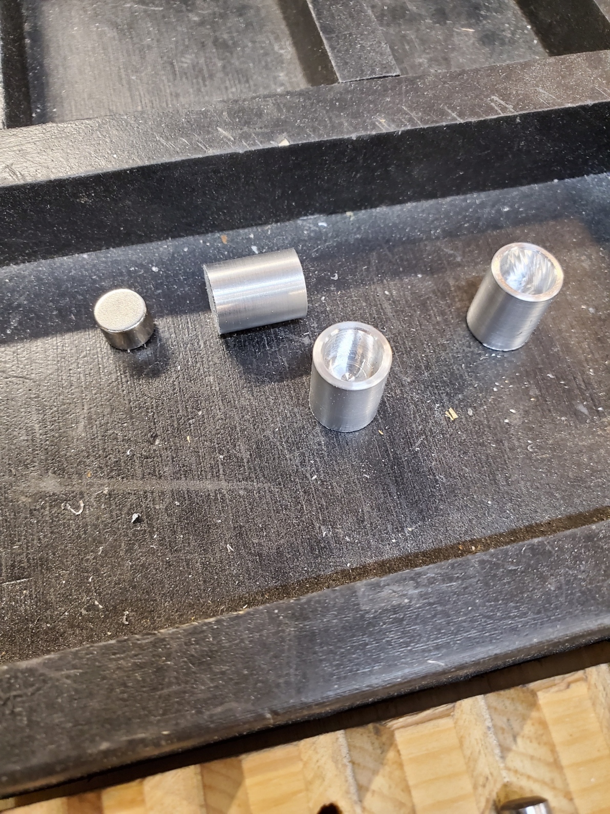
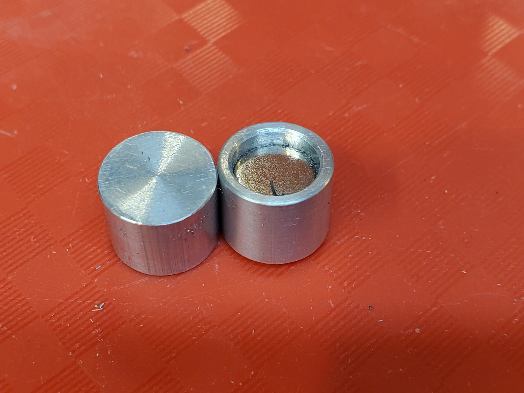
I made 3 feet from aluminum round stock and glued a rare earth magnet inside. The feet were made in a bucket shape with a very small bit of aluminum between the magnets and the lathe chuck. The feet are held to the legs by the magnets, and the magnets hold the stop to the lathe chuck.
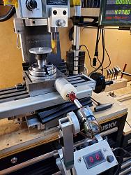
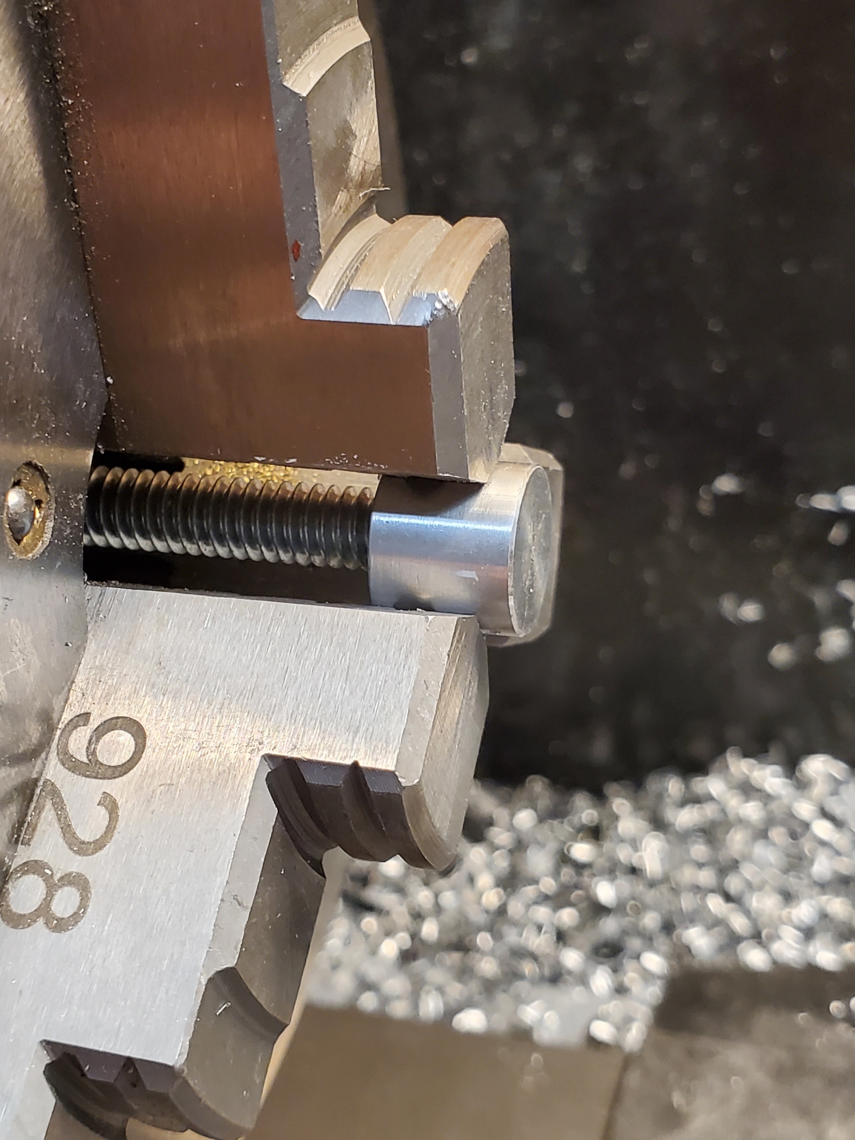
It is important that the feet all be the same effective height so that they can be used interchangeably on any leg. As anyone who has glued a magnet into a hole has experienced, the magnets do not always set at a consistent height. I used my internal stock stop to position each foot in the lathe chuck and I faced off the end of each foot to make the effective height identical on all 3 feet.
This is a perfect use for the internal stock stop. It allows very precise, repeatable positioning of the feet in the chuck for machining.
It should be obvious that the lathe should not be operated with this external stop attached to the chuck.
The book that inspired this design is:
Useful Machine Shop Tools To Make For Home Shop Machinists by Stan Bray, edited by George Bulliss. (No affiliation.)

The design in the book used grub screws to secure the legs and the adjustment knob. I decided to use jam nuts because grub screws will damage threads when used like this. Such damage is OK if you are certain that you will never have to take it apart or adjust it for any reason.


 Reply With Quote

Bookmarks