
 LinkBack URL
 About LinkBacks


The construction company installing the fiber cable for our area phone lines noticed that I have several machines while they were upgrading my landline service. yesterday their maintenance guy stopped by to ask me if I could or would do a repair for them.
retirement being what it is why have all of these machines if I'm not making or repairing something with them.
So I drove out and had a look at the problem.
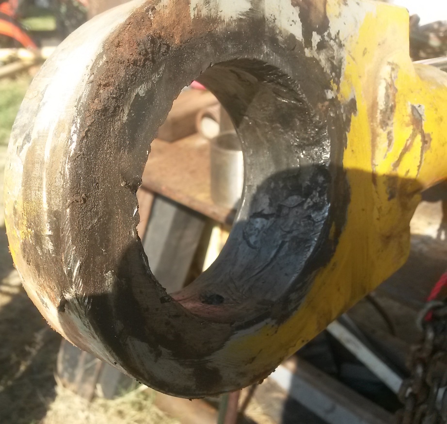
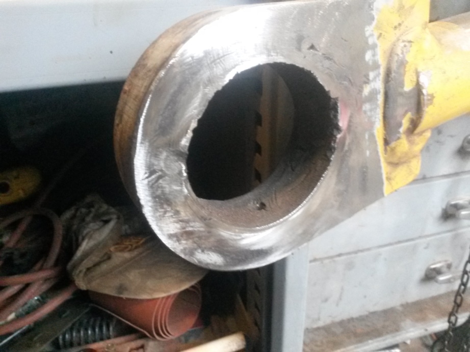
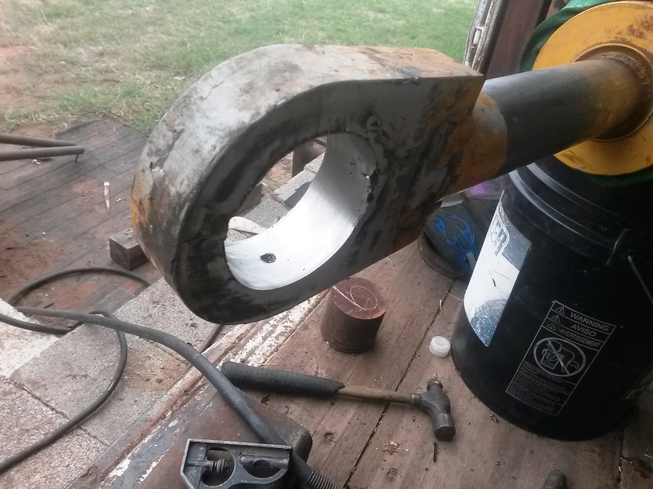
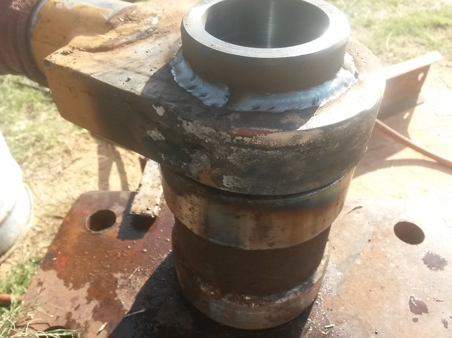
A Hydraulic cylinder with a spherical rod end that he said keeps shattering the bearing cup.
Sure it does it was the wrong application for the size bearing and there was no need for a spherical bearing to be there in the first place.
The superintendent said they have replaced the bearing a dozen times in the past 3 months and he wanted a solid bushing or sleeve type bearing installed in place of what was there.
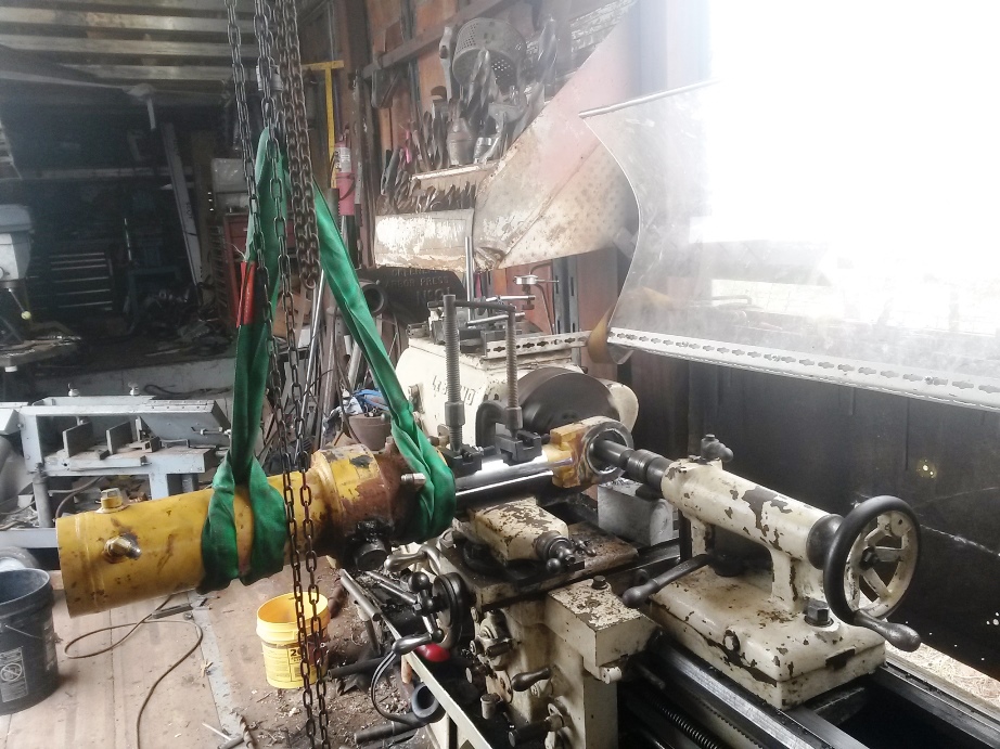
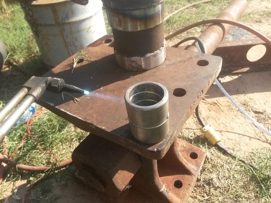
They pulled the cylinder off and brought it to me last night so here is what I had to do
First off I noticed that what the man wanted wouldn't solve his problem for the long term. What he wanted was to simply machine a thick bushing a little wider than the rod end and press it in then weld it in place. Which would have been fine except when the bushing would eventually wear out it would have to be cut out and another one made.
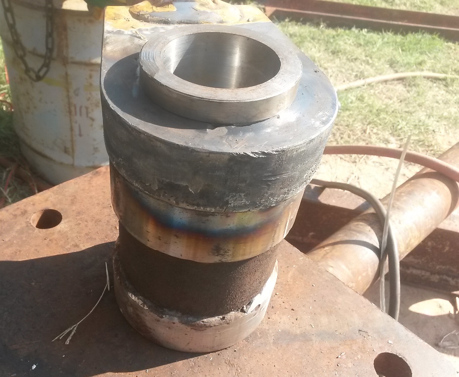
I decided to take this 1 step further by making the bushing then making a sleeve bearing to the size of an off the shelf standard sleeve bearing.
But the rod eye bore was severally damaged so first that had to be taken care of
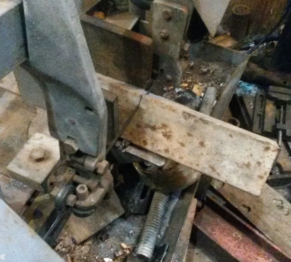
Now how to hold this thing in place so I can bore it out
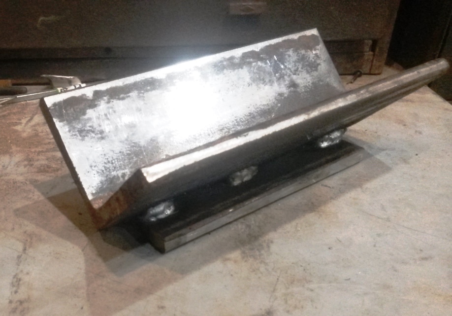
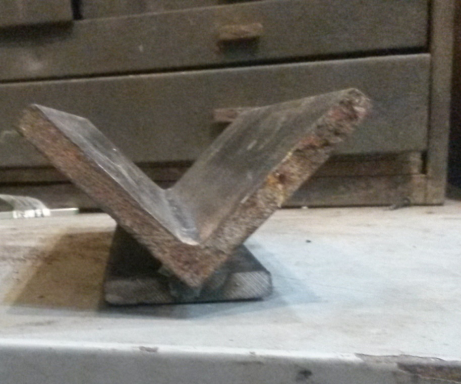
I know I will make a fixture and clamp it to the compound and cross slide First I cut a 8" long 3 x 3 x3/8" angle from scrap
next I cut another piece of the angle then clamped it down to cut off a strip to fit in the holding slot of the compound.
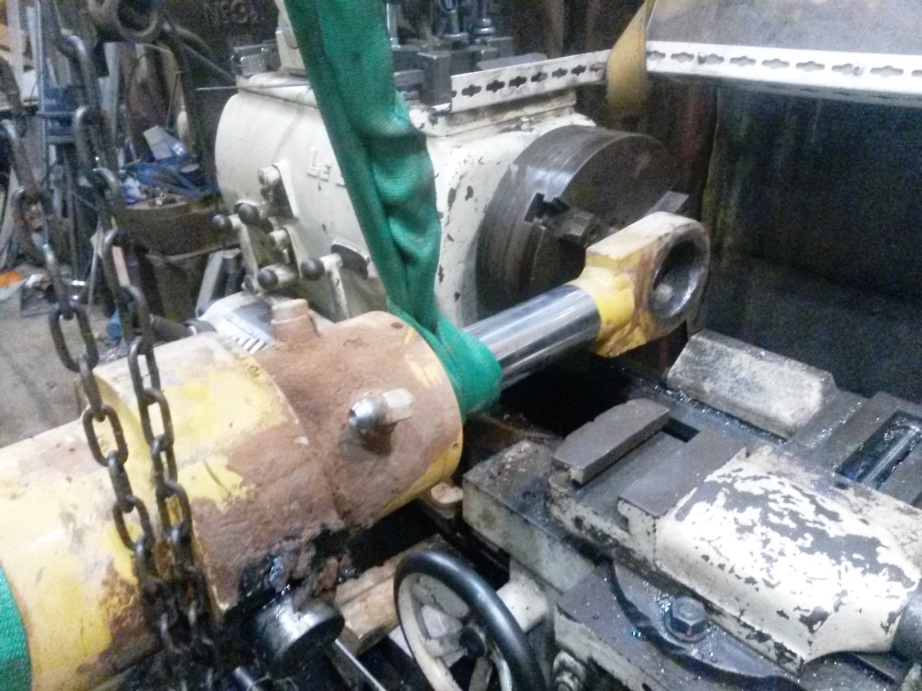
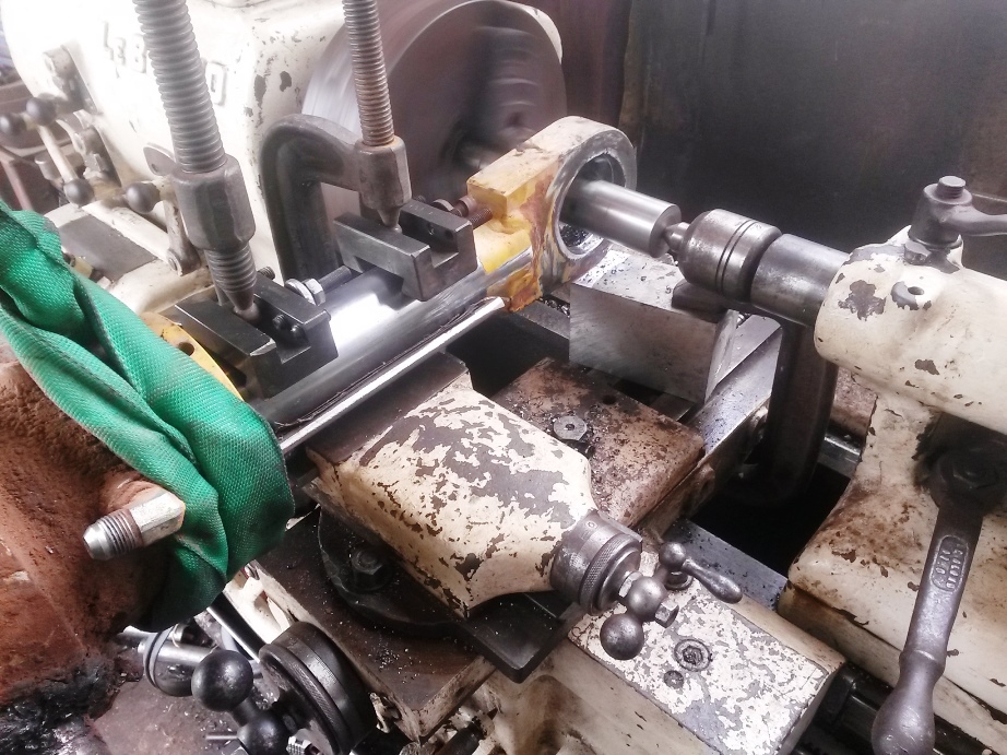
Next I cleaned up the face of the rod eye
Here you see the fixture with the cylinder rod clamped to it and the boring bar to clean up the rod eye
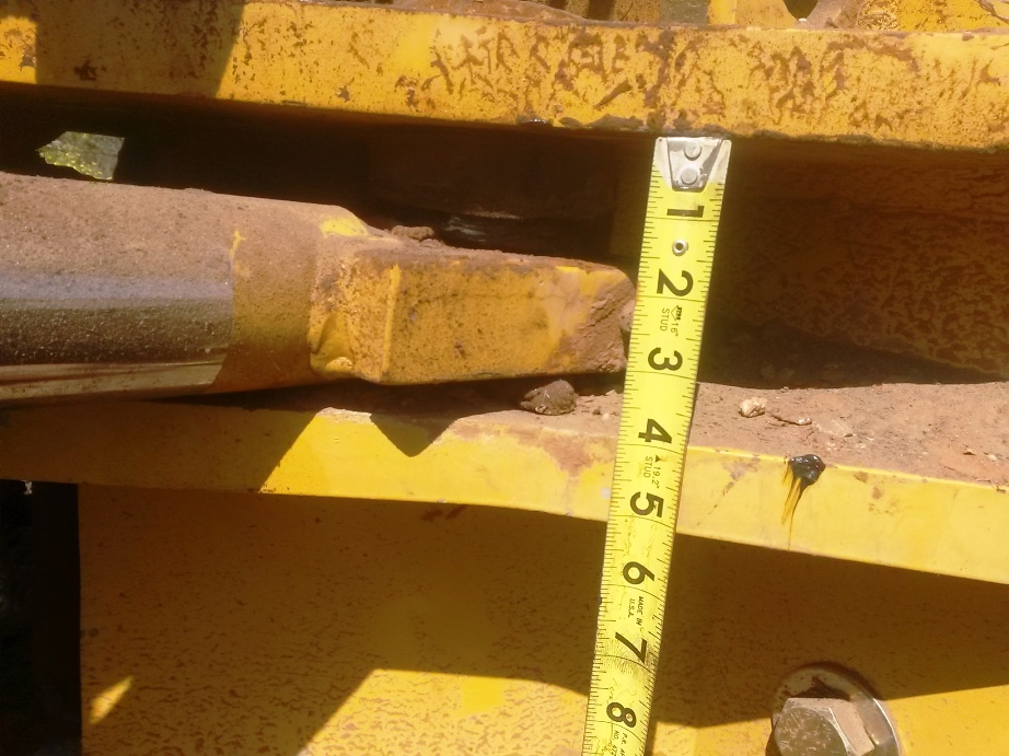
Note the missing paint near the end of the rod where it joins the eye. To make sure the bore was perpendicular to the rod I checked the alignment of the rod to be parallel tot eh lathe chuck by using a known straight cylindrical bar positioned against the cylinder rod then measured the distance to the lathe chuck face with dial indicator the magnetic base on the chuck I rotated the chuck until the needle struck the bar at the horizontal my chuck is 12 " in diameter so I was checking the bar that distance apart I figured it was close enough once I found zero in 2 places.
Another view Has anyone ever used tool holders as clamps
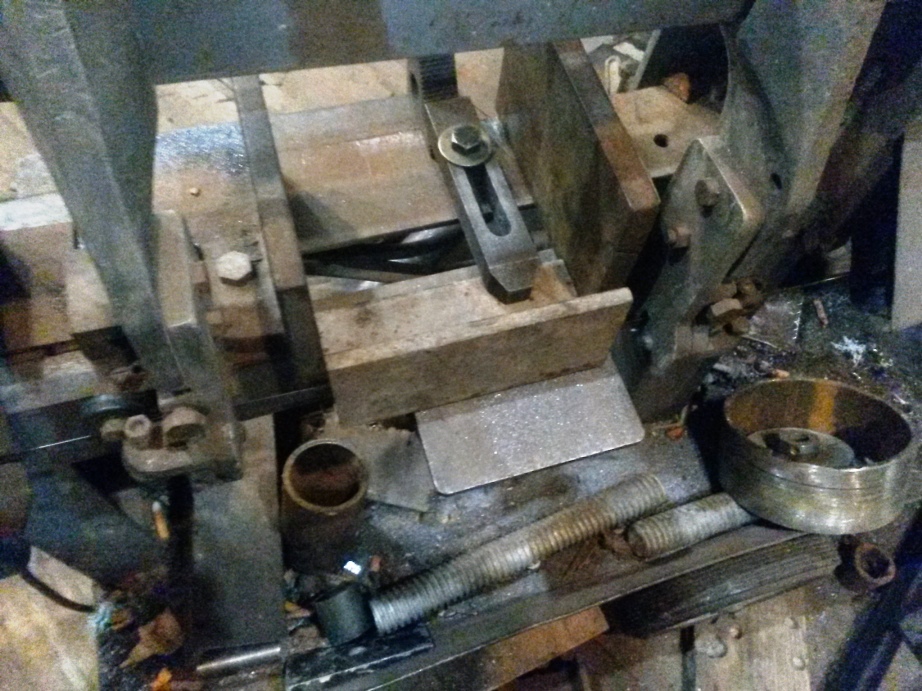
The fixture
the bore cleaned up


 Reply With Quote
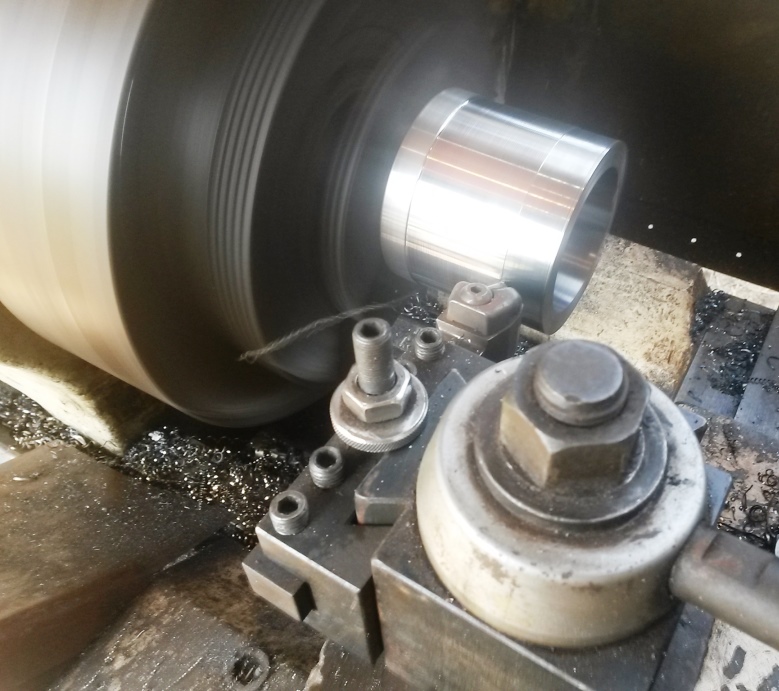


Bookmarks