Looks like a Nice, clean winding job. Is that Teflon around the outside? The EL34's look great...Nice find! Thanks for the update.
~PJ :popcorn:
Printable View
Looks like a Nice, clean winding job. Is that Teflon around the outside? The EL34's look great...Nice find! Thanks for the update.
~PJ :popcorn:
Around the outside I used a strong paper used for electric motor, should be mylar paper according to old man who gave it to me. Very rigid and in various thickness, I used 0,2mm. He gave me also a very nice mylar scotch tape, close to perfection to keep winding in position. Unfortunately calculations foresaw slightly different values, I got maybe a bit low inductance and resistence as anode choke. Some manufacturer has anode choke of high impedence (80\100H for 10-20hz use), I don't need low cutoff frequency, but I got some doubts about this. The good thing is that I got space in bobbin, I can wind maybe 5x of actual turns, and maybe this time, with lathe, luckily is only an inductor :) obviously I will try to do by hand
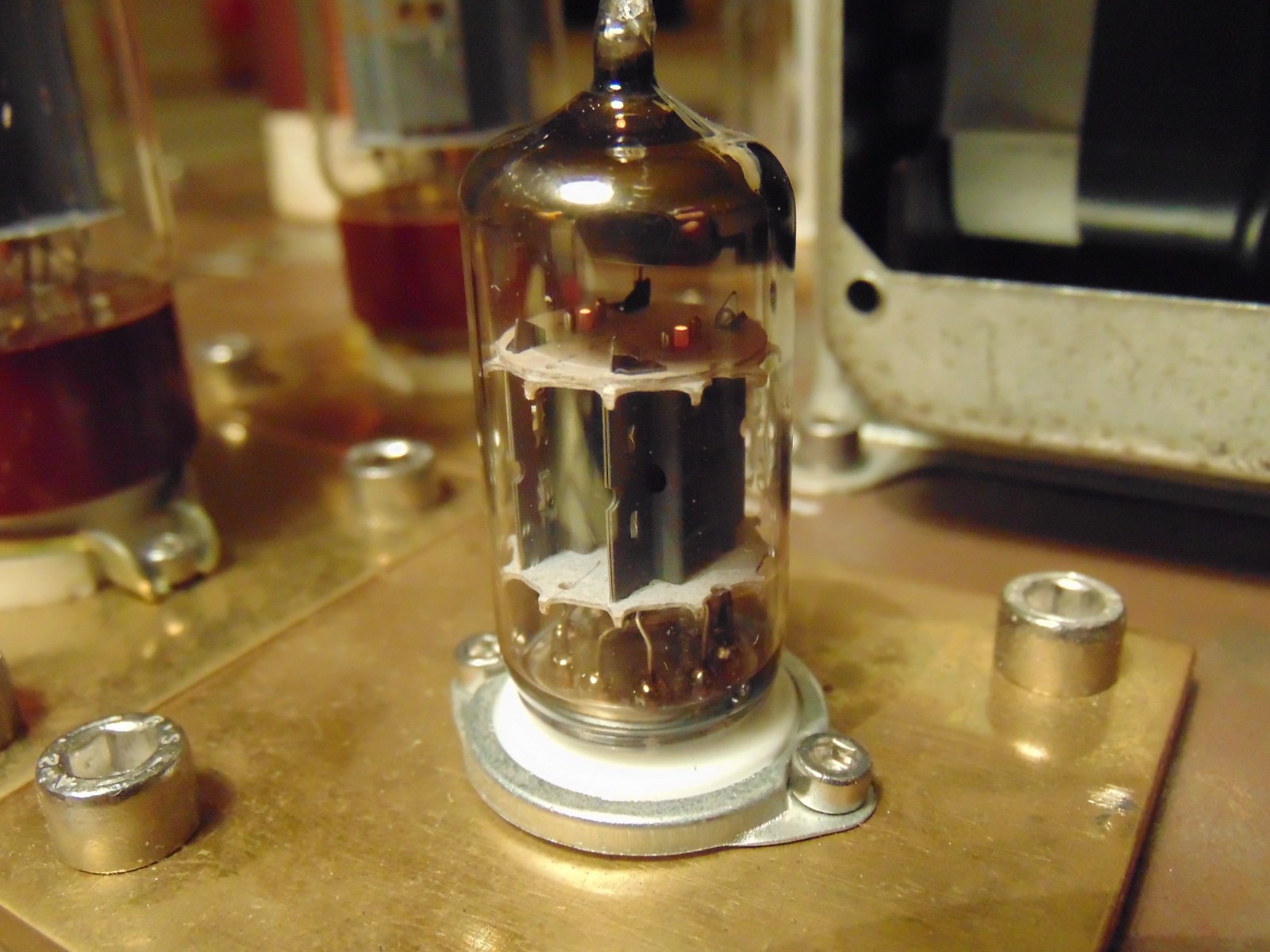
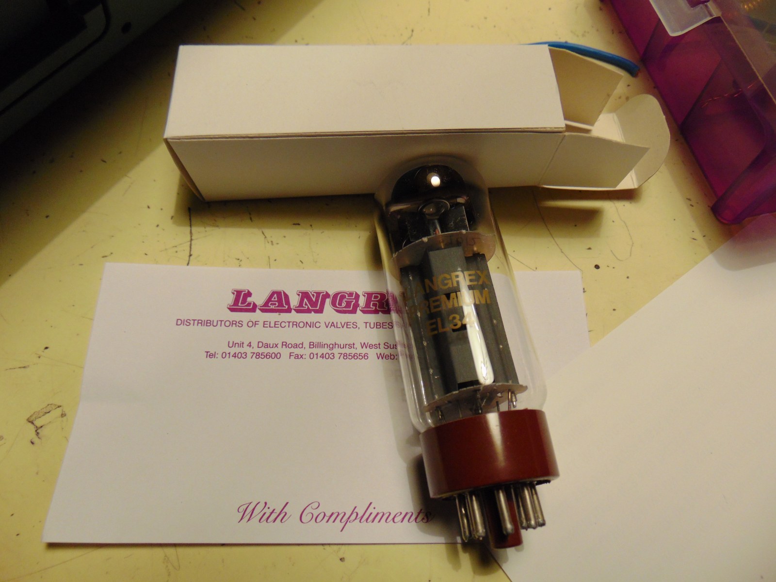
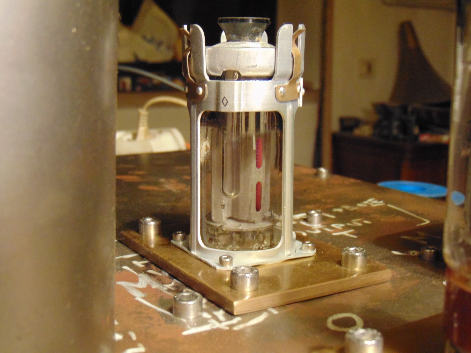
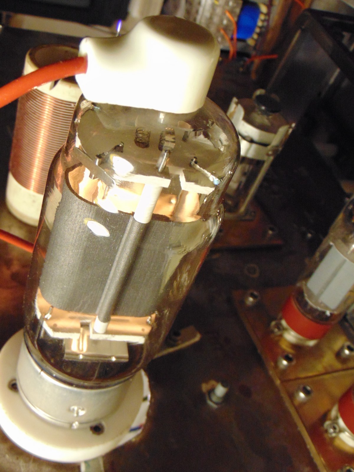
This El34 tube are made for Langrex, a uk company of tubes and electronic parts. For sure made in Cina by Shuguang factory, quad matched. Imho this production is a "good selection" of el34, maybe matched in factory during test. I would like to think so :D . Even if they were only fables, 15 euro shipped each tube is a good price. In my city shops I've seen similar price range tubes ( chinese, JJ, elettroharmonix ) from 22 to 45 each, even on ebay price are good.
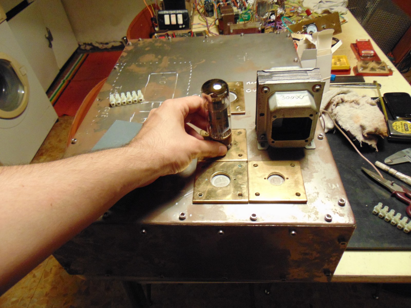
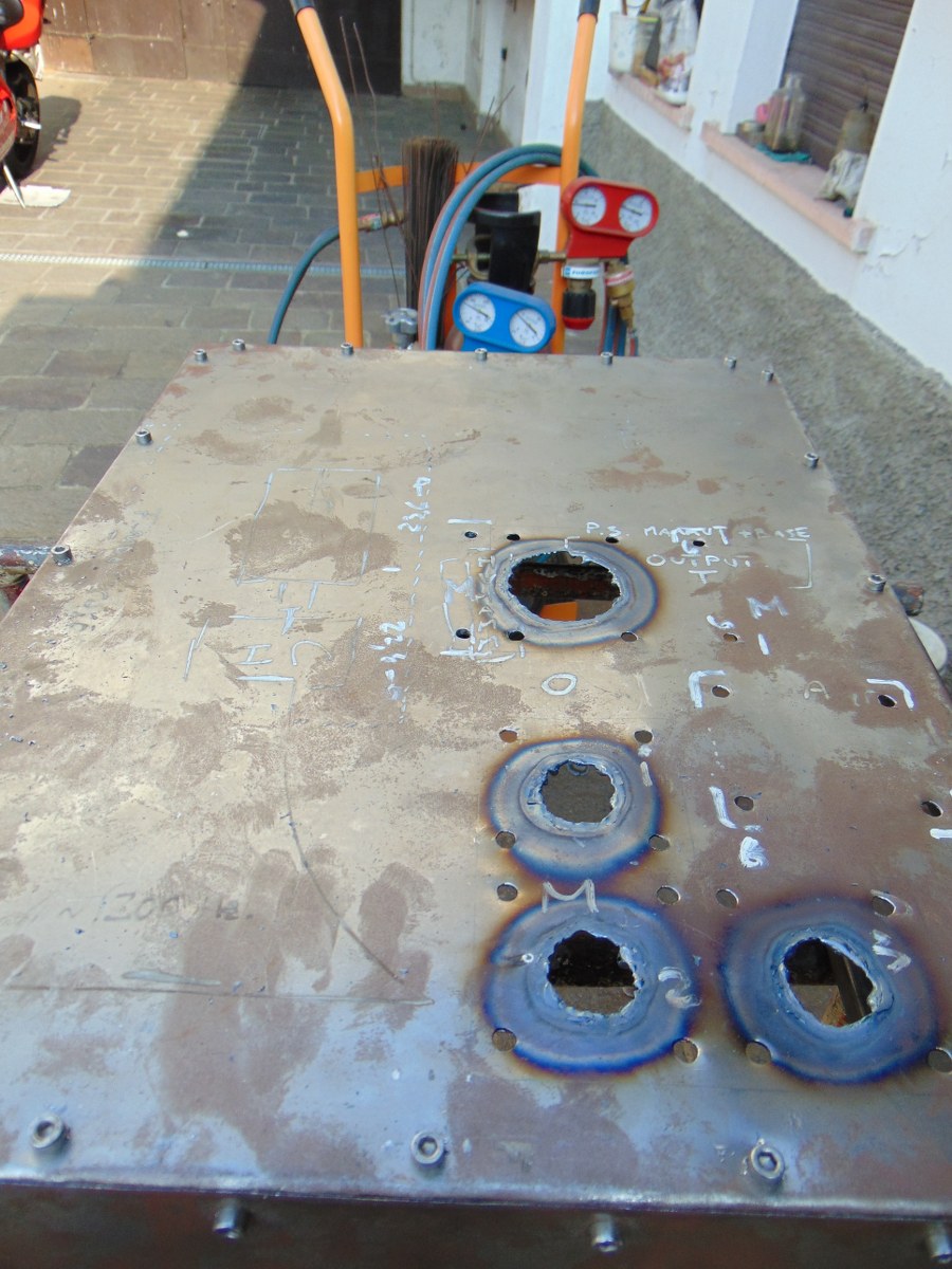
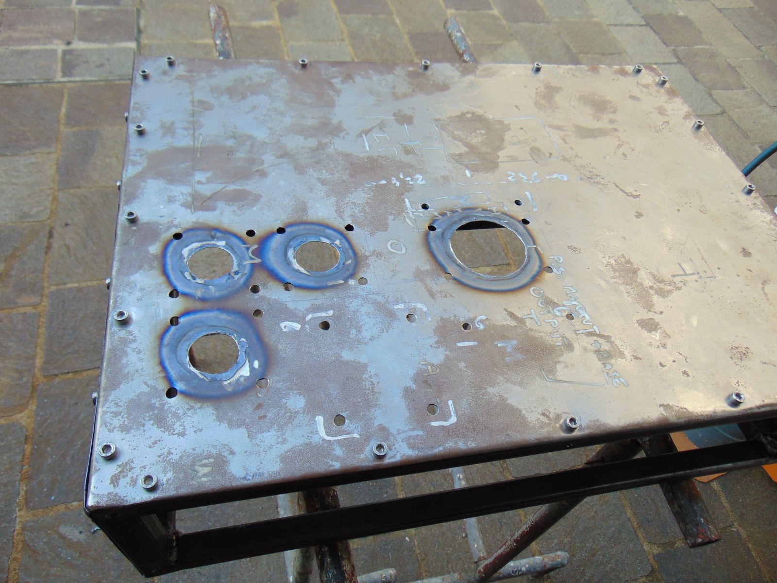
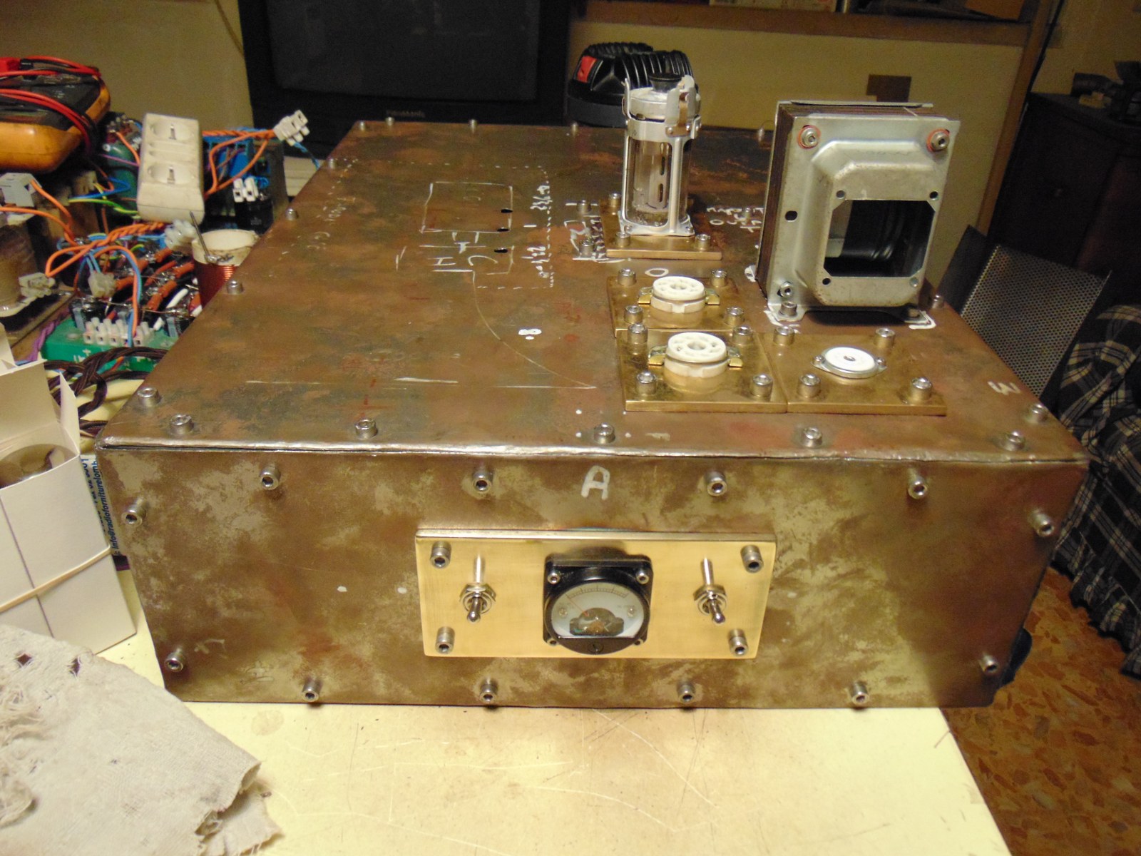
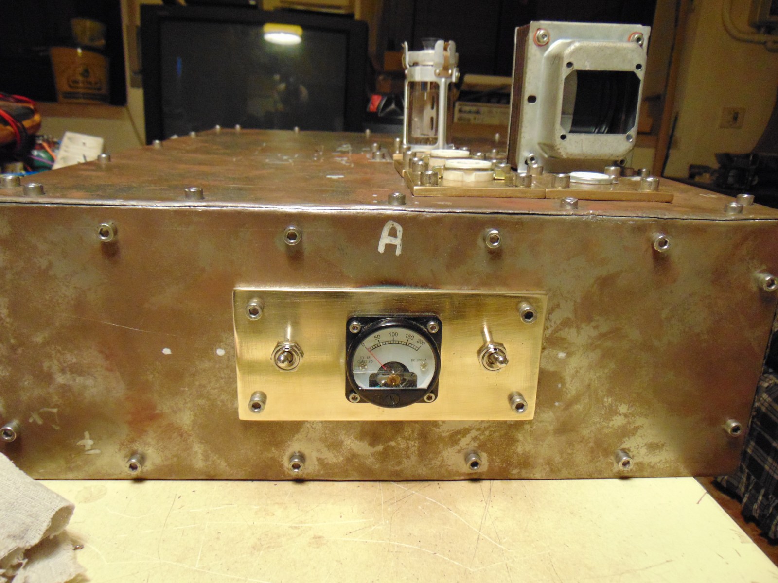
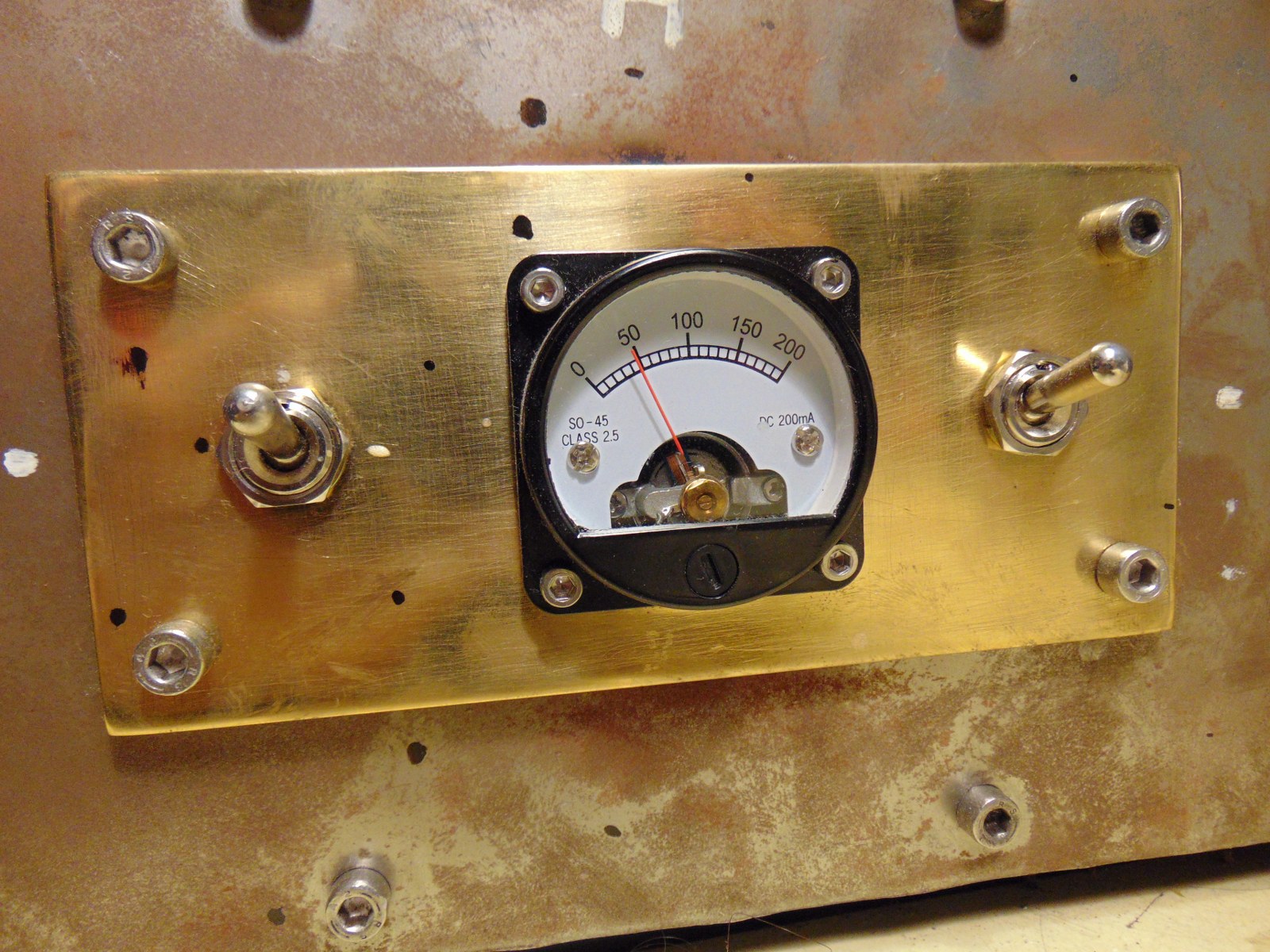
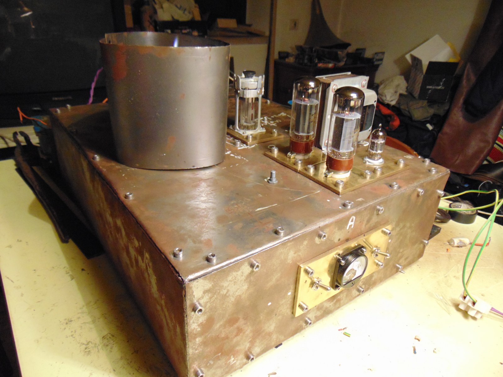
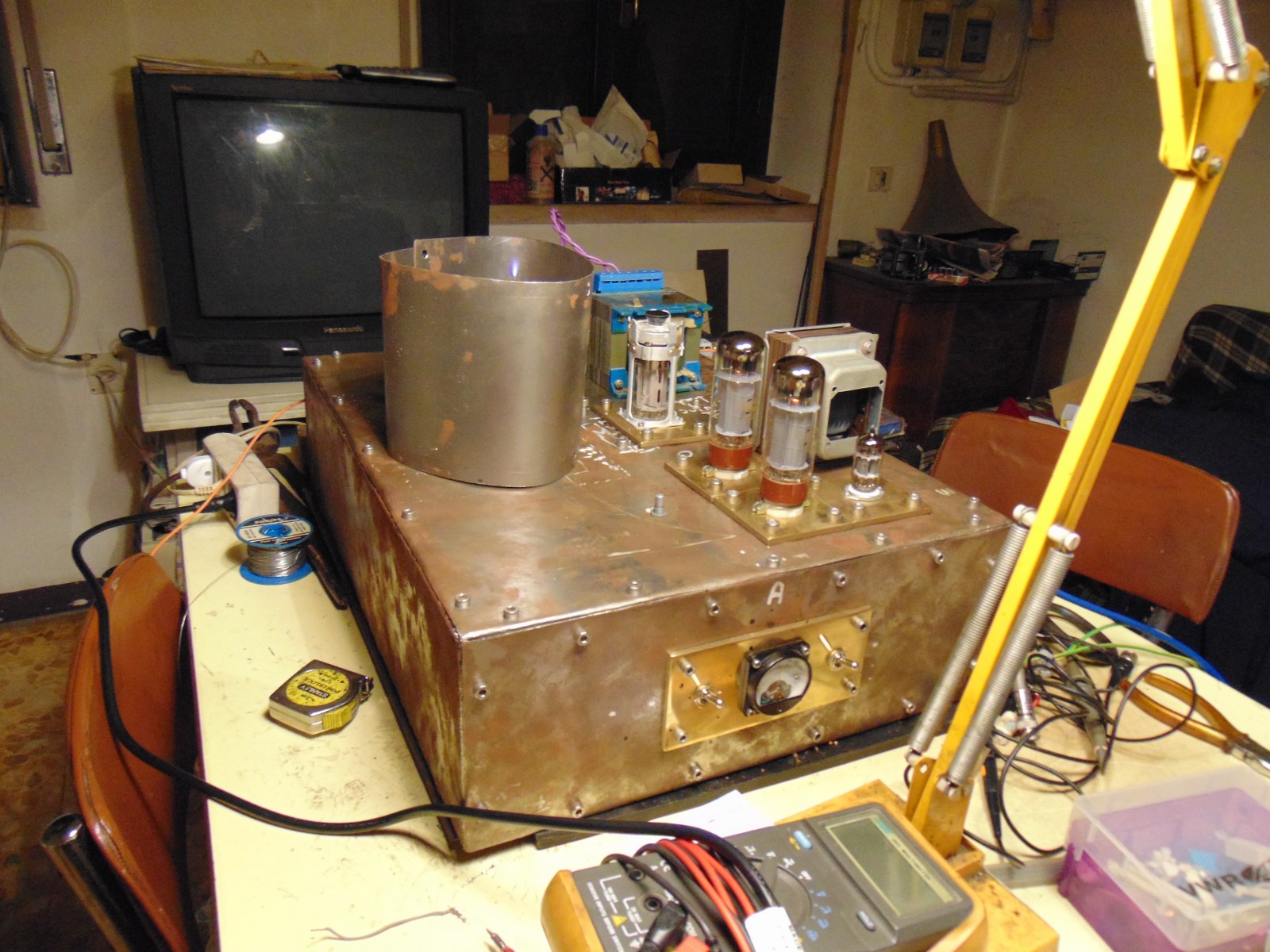
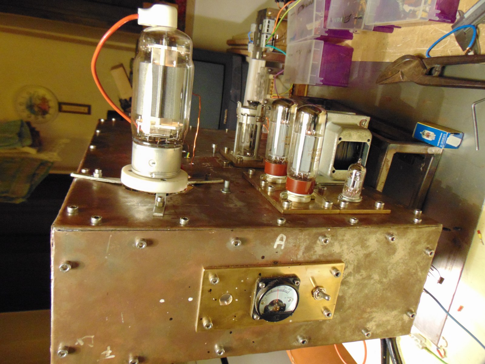
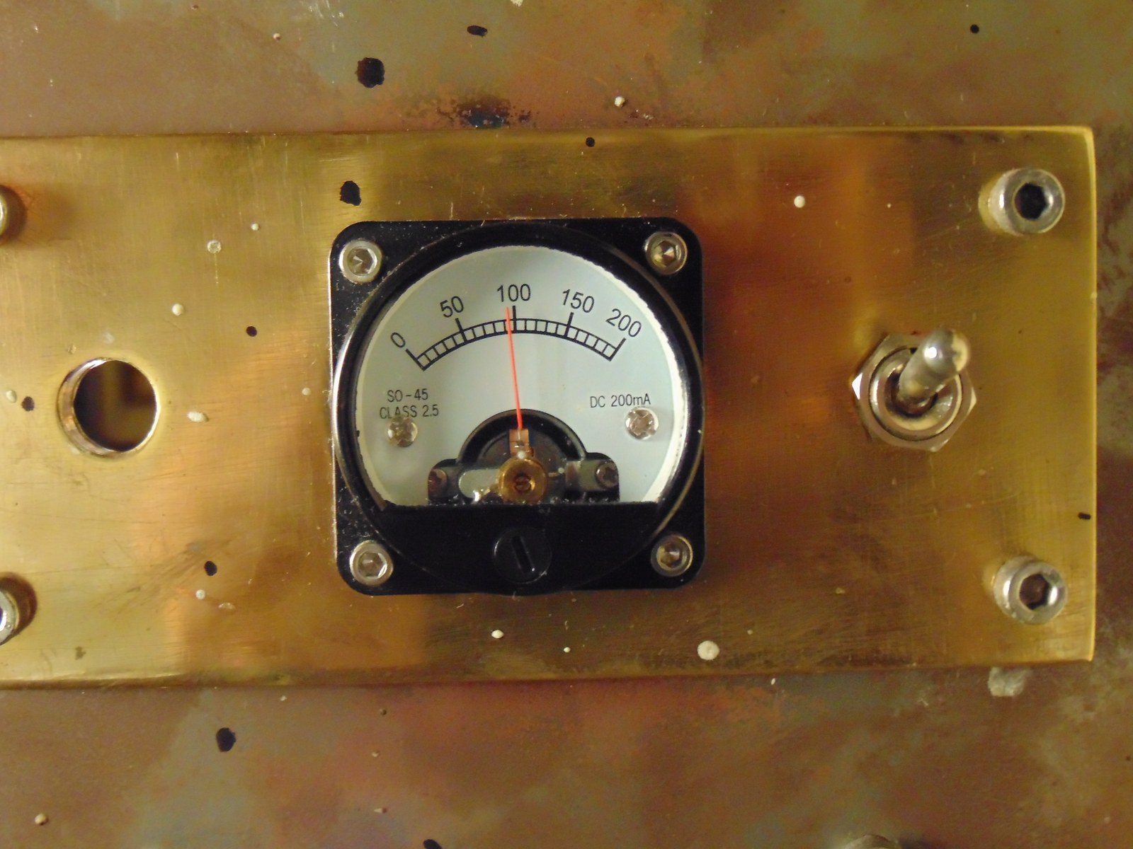
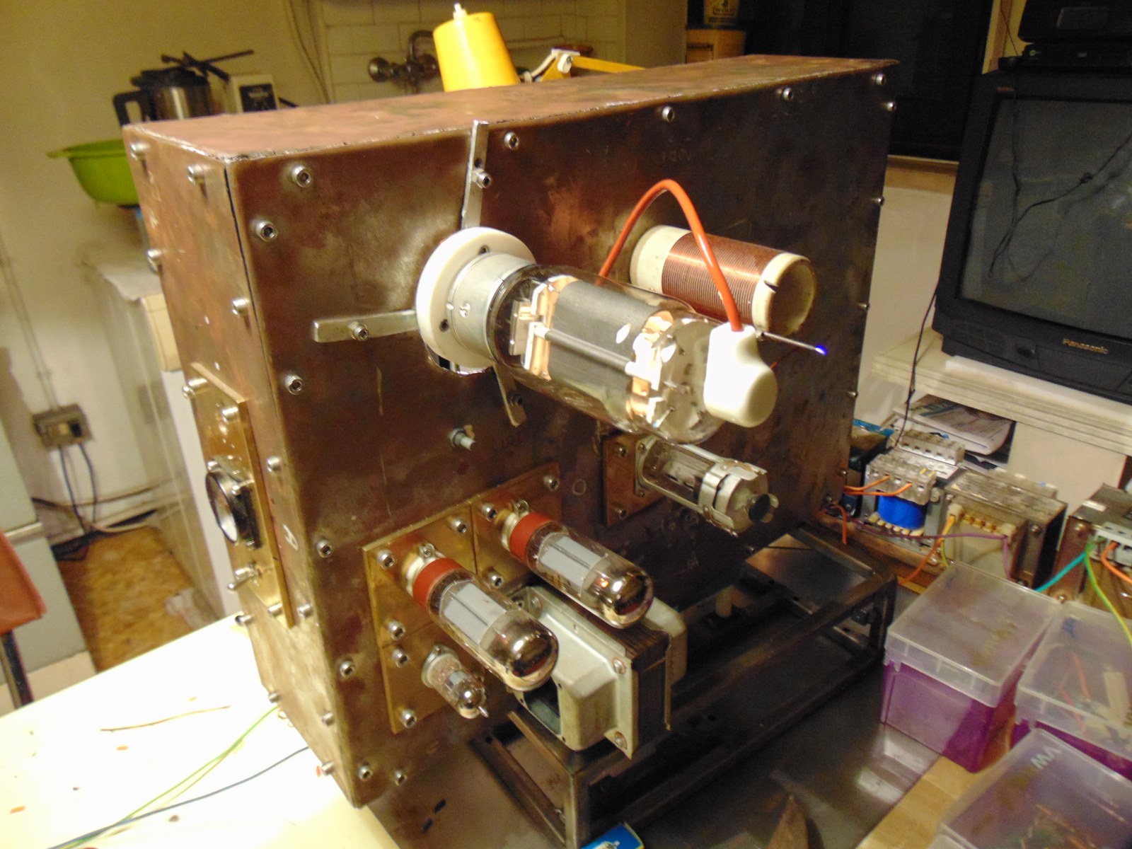
I try new layout, I'm trying to make a good use space. For final version, no potentiometer, no volume, and switches in the back, in order to not keep around half meter of 6 cables for power supply. I have to find a good amperometer and maybe a voltmeter till 2kv, not easy to find, unfortunately! This evening I made a couple of support for power supply and Hv unit, to Mount close to sockets.
I changed Gu50 position because heat, and thinking the worst scenario, the replacement of final oscillator tube with one of a higher class (Gk71 - 813 for example). I really want to keep gu50 in circuit, because it's good, but you never know... better to get hands on :D
I'm not sure if it's better to use milling machine to open large drill on thin steel, or maybe use the oxy torch, for sure a fast work!
Attachment 13902 Attachment 13903 Attachment 13904
Nice the old guy gave you some paper and Mylar tape. The paper, if made for xformers will be fine with a layer of tape over it. I know you are winding this yourself and it's a pain, but you can change your inductance with the gauge wire...but still depends on the frame quality, laminations & permeation you have. 80/100H does seem high but not sure in this case either.
Really good prices on the EL34's especially if they are Matched...wouldn't count on them being perfectly match but close would be great for this stage.
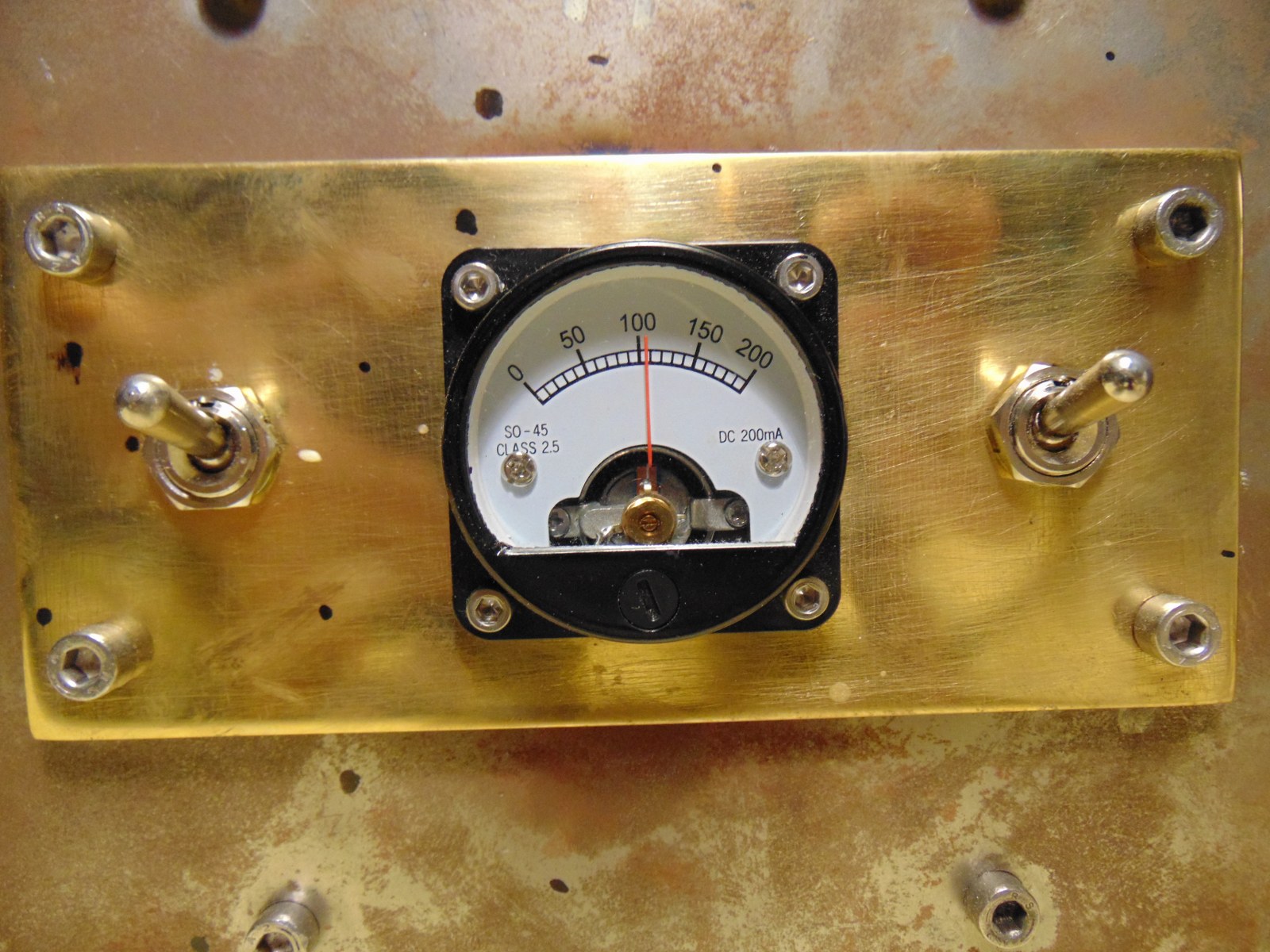
Glad you are shortening your wire runs it should really help in the isolation. Perhaps you could run the low voltage stuff on one side of the frame and the higher on the other. What is the amp meter for? For the amp meter you can always use an external shunt with an MA meter. A 2kv voltmeter is a bit more tricky to find but again you could build a small external voltage divider circuit...in both cases you'll need to rescale the meters and they will lose some linearity.
I'd think the mill would be better for the larger holes, but you need to work on the cutting geometry of the boring setup you have...although you might find a hole saw (~$15-20) the right size and go slow (peck it) with lube. Give yourself plenty of clearance to the hole in your brass plates for wiring and isolation. To me the torch would mess up your pretty work so far and need a lot of clean up.
Good progress! Thanks ~PJ
I'm trying to understand how plate choke runs in circuit, I read many things, but this site puts confusion in ny head:D
Magnequest Tech: All choked up on Grid and Anode Chokes
Reattanza induttiva online fast calculator
My need is a 100ma coil , for a 3,5k load in pentode mode el 34. (15 kohm internal resistence for el34 in pentode),
For sure, normal audio amplifier should reach 20 hz min frequency, for normal operation. My plasma will be start from 1000hz, ideal starting frequency, maybe it can fall to 500hz, but horn becomes big
Magnequest advice is to keep 8 times internal resistence of tube, talking about output transformer, and in the middle of page the formula of reactance. I have trouble understanding this site because data imho are confused
Magnequest Products - MQ Iron Listing/Pricing
Let's take for example BAC80 model, rated 80ma, 50H , 325ohm resistence (same current of my amplifier)
Formula gives for 50H and 20hz freq, 6280 ohm of reactance , that is +/- double than the recommended 3k load for pentode, but still usable as load for the same amplifier.
According to site, why to 8x the internal resistence of tube? can be a good rule for a low resistence tube, but not for a pentode imho.
Calculaton for my inductor, 3H , at 320hz give me a reactance of 6K, that's double of normal loading of my tube. In theory, if I filter the imput with and high pass with this value, everything should run ok, or I overlooked something?
I think I'll find out soon :rolleyes:
Ps: I used oxy torch, and file, because frame was to big to lock on milling machine
Ps2: I'm thinking about data
- 8x internal resistence = inductance es: 8x 15K = 120H (at 20hz)
- my inductor is 3H, reach 15kohm of reactance at 750hz
- if I want to lower frequency, keeping 15Kohm minum, I have to increase inductance at 7H for 320hz for example, or 25H for 100hz.
my question is: why 8x the internal resistence?
Attachment 13923 Attachment 13924
Attachment 13925 Attachment 13926
Stephano, I feel like I'm back peddling here at this point again. First I don't know if you are changing the EL34 circuit to a single class A or push/pull double...but you said pentode mode so that helps in looking at the curves on the cut sheet. Second you never said what your differential g1 voltage is. Third in your calcs I don't know where you got the 325Hz from but if you put the numbers in the calculator you get 6K-XL...yes. Yes the Ra is 15K for pentode mode (see below).
The Manquest Tech article is pretty dry reading and a bit jumbled IMHO. It does clearly state things in a way to sell their products and why. Basically your coil looks to be a low leakage CMC but the cover will help with shielding...but again shooting in the dark because of conductor size/type and core type. In your BAC80 example you say that it is double the 3K load...but on the cutsheet page D2 under a "distributed load grid tapping 43%" it does show 6K in Push Pull and I am Assuming that is an XL value. @¿@ Have NO idea where or why they came up with the ">=8H per kohm of R_plate measured at < 1/10,000 of rated output power". Especially with the <1/10k rated output power. They must have some serious equipment to be able to measure this and or it may be some Physics/EE thing I forgot after 30 years. The site is definitely for Hi End audio file components though.
Honestly, I can't say if you missed something or not so All I can do at this point is sit back and :popcorn:
I get it about the torch/mill size!
~PJ :popcorn:
Sorry, I thought I wrote in previous posts :rolleyes:
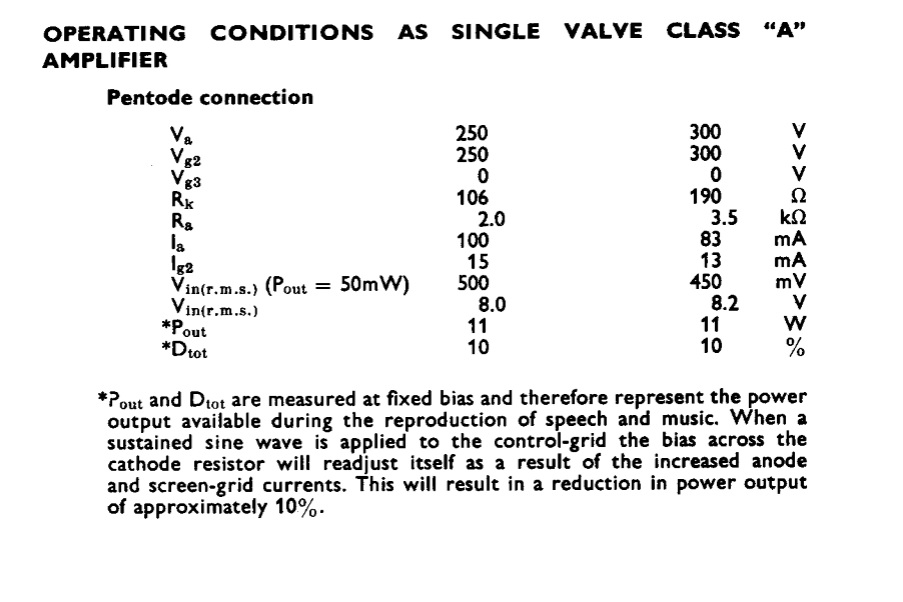
El34, amplifier part, for now follows datasheet specification, then :
anode voltage 300, grid 2 300v, Rk 190ohm, Ia 80ma, Ig2 13ma, 11w power output with 8.2v g1 load 3,5k
I'm also thinking about second working point, for same output , with different load.
anode voltage 250, grid 2 250v, Rk 106ohm, Ia 100ma, Ig2 15ma, 11w power output with 8v g1 load 2k
https://frank.pocnet.net/sheets/129/e/EL34.pdf
Is nothing more than the official data. I will modify the circuit if necessary, but I think it's a good starting point.
Forgot frequency, numbers and formulas for now. I see that in similar amplifier circuit, when it's used an anode choke instead of an output transformer, values of inductance change for some reason between the 2 parts.
Compared to normal output transformer (3.5k load , 15H), inductance numeric value of an anode choke for the same load is maybe 50H or more. I tried to explain to myself with the formula of inductive reactance of coil, observing the products and the results I concluded that:
-For an "X" tube with "Y" internal resistence, anode choke inductance should be chosen 8 times the internal resistence
putting in calculator 15k x 8 = 120H , and 20 hz frequency the result of reactance is 15kohm, same as internal res of tube.
I deduced that for normal hi-end audio (range freq 20hz - 20khz typically) (8x is the "rule" in order to make a good anode choke for "X" tube.
-second step, reactance formula is valid at a certain frequency. I don't need 20hz in a tweeter, range will be 1-20khz for example.
It's important that the low-end frequency of my inductor (anode choke) should have a reactance equal to internal resistance of tube.
My 3H coil for example, has a reactance of 15Kohm at 750hz. Taking the lowest frequency value for 15k, this coil should be good for an amplifier that sounds from 750hz to 20khz.
Using formula, I can keep 15k (I need this value fixed), I can also lower the frequency, at price of raising inductance of coil, then for example if I want my amplifier sounds from 100hz I will need 25H coil in order to have 15k reactance.
I think you're right about commercial sites, in particular this magnequest is pretty dry of info! I only tried to use this info to make a sense. Unfortunately even books have not satisfied my thirst for knowledge:D
One thing is sure! this post is pretty useful for my to keep record of all modifications done
I hope this page could be both of leisure and good reading even to the forum members:)
Attachment 13932
A good evening with a friend and some bourbon :)
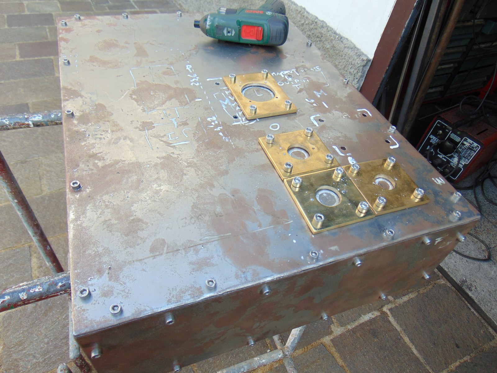
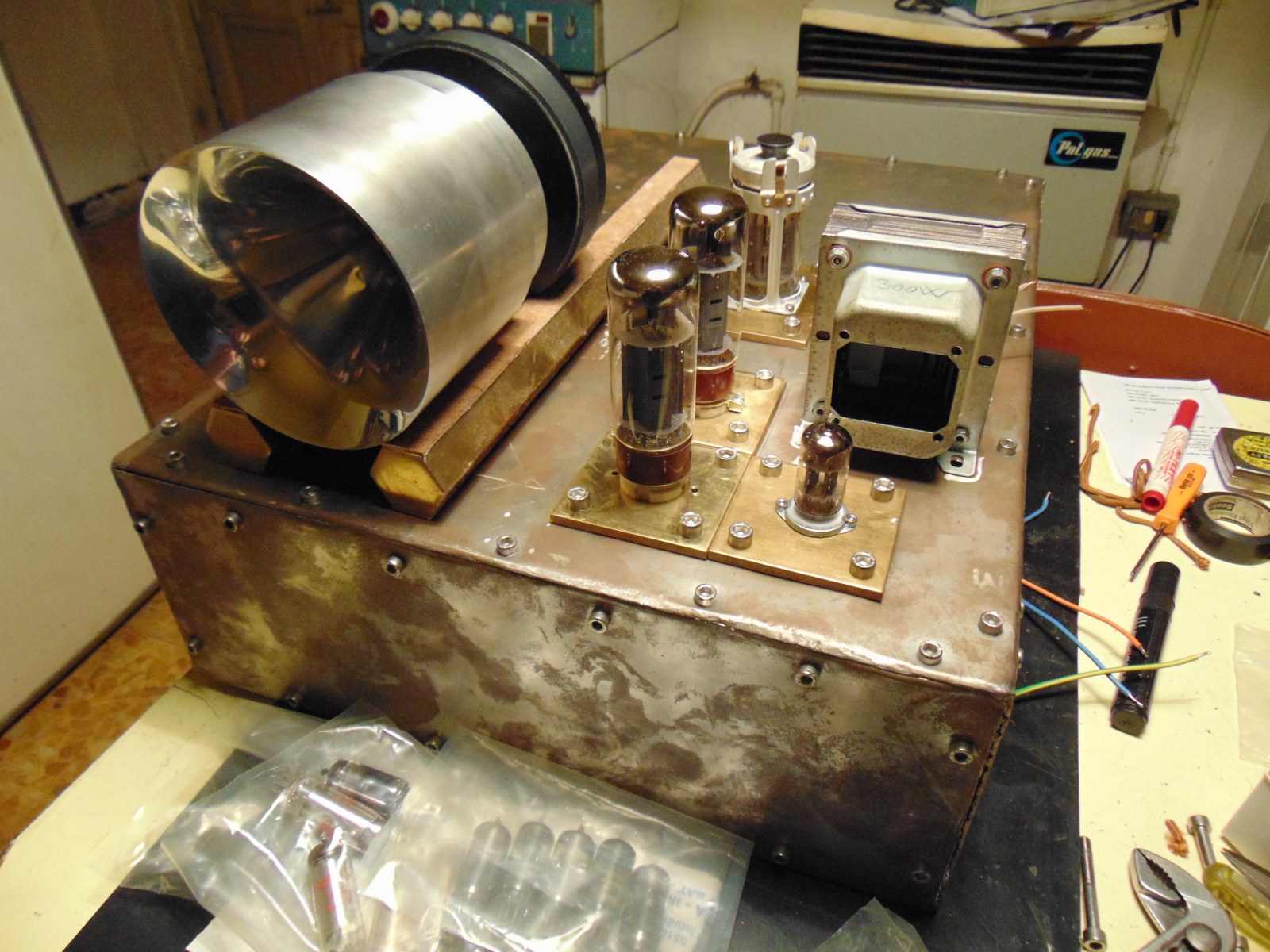
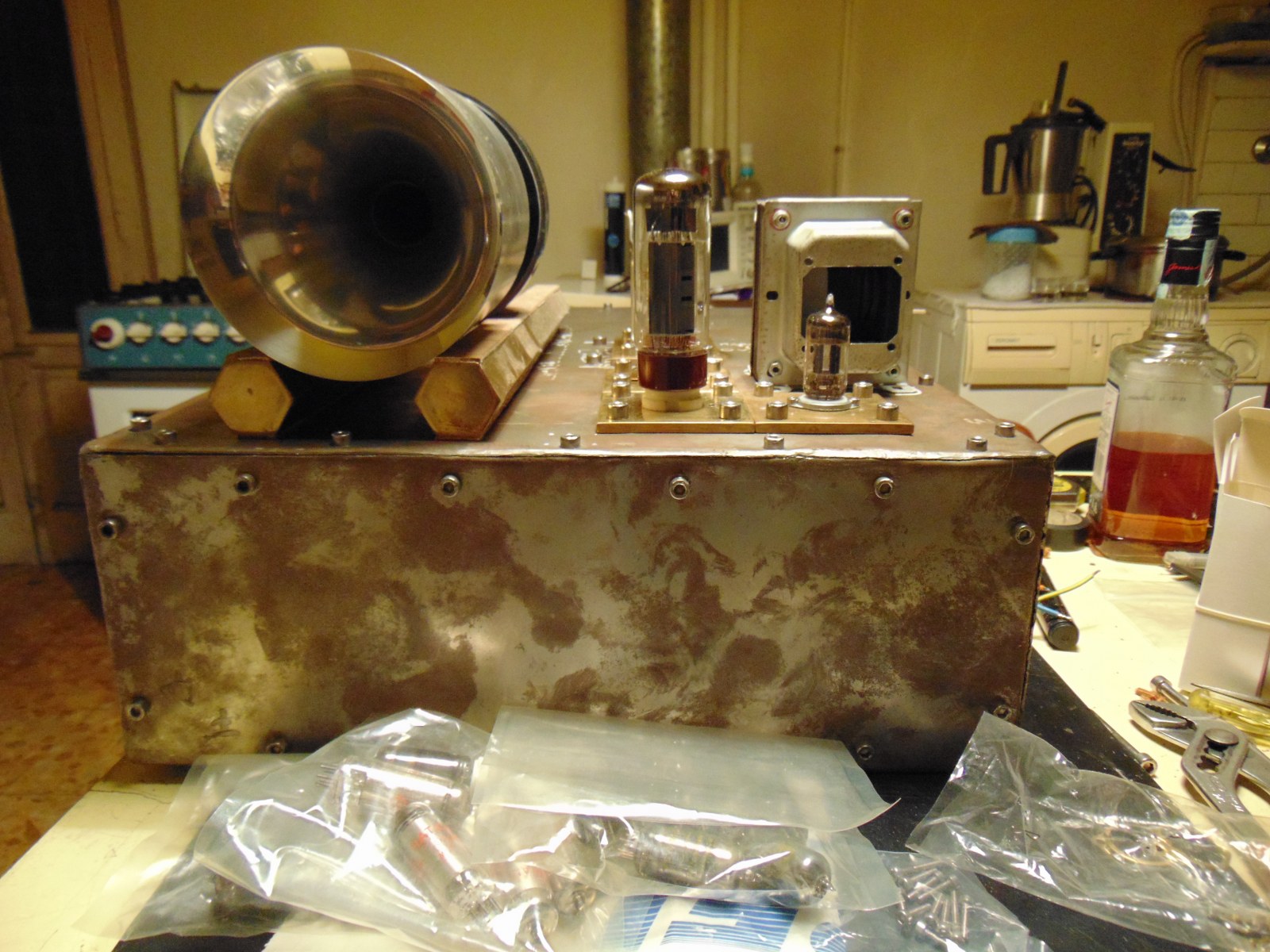
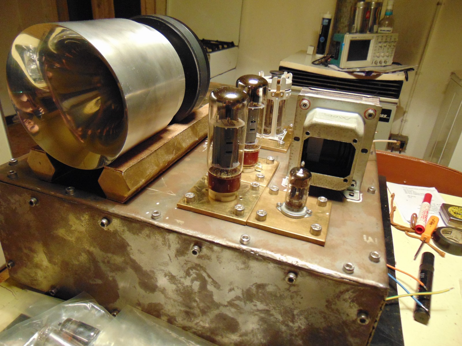
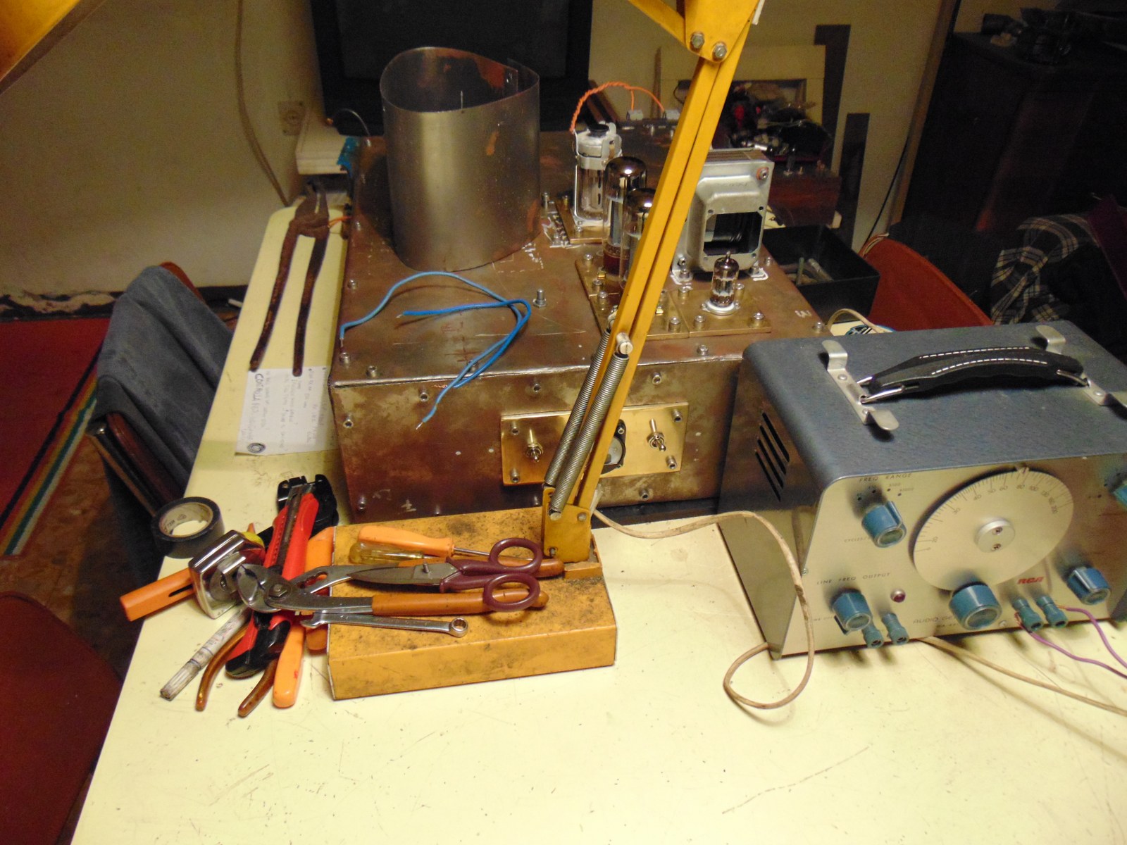
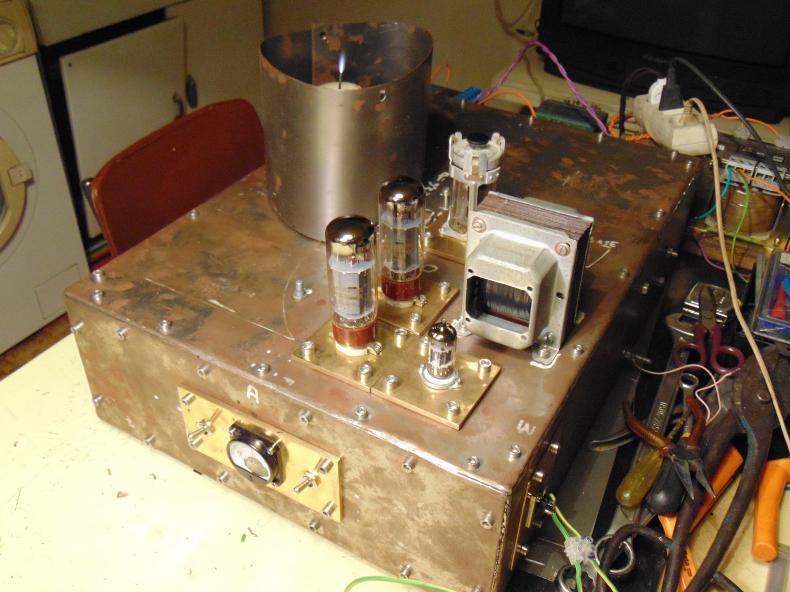
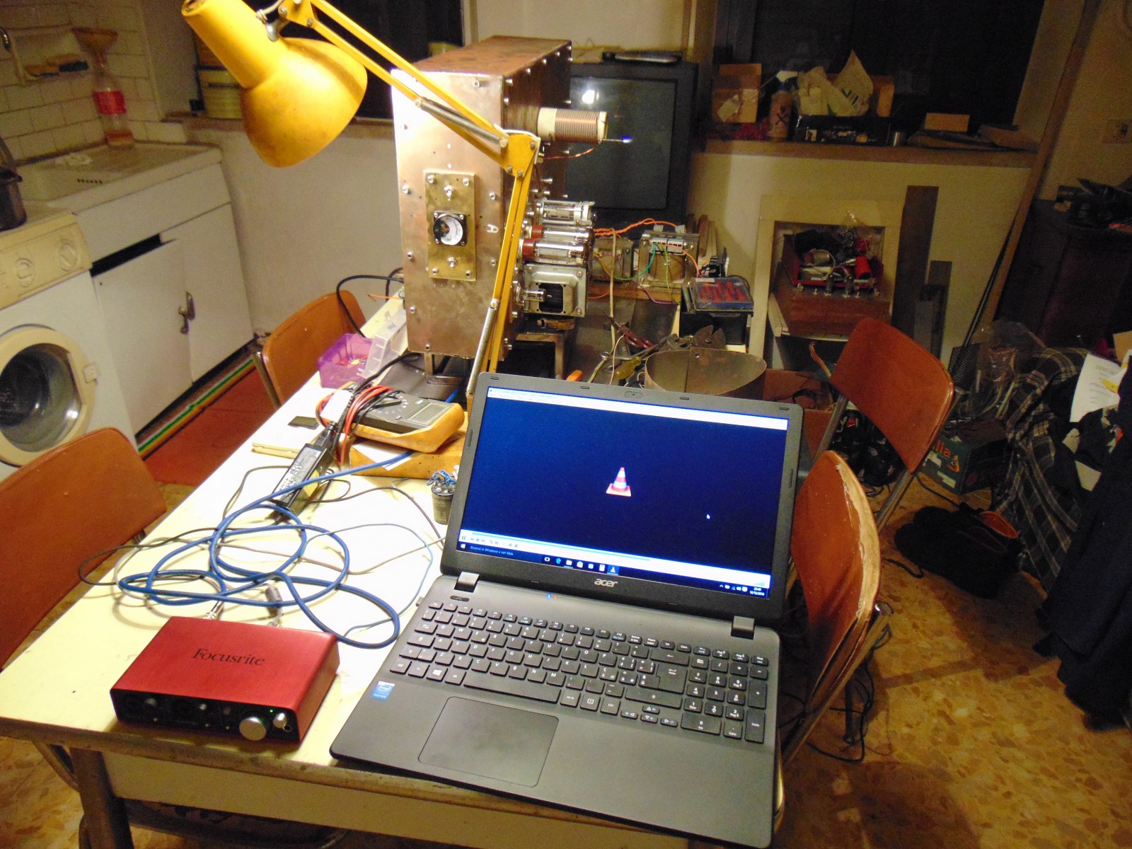
I'm going to put parts on frame, and trying to imagine a new plasma tweeter. Position of sockets is good, I'm thinking about powersupply transformers, switches and other parts. I think I will buy a single 500va toroid and put a couple of relays in order to cut high voltage and maybe filaments.
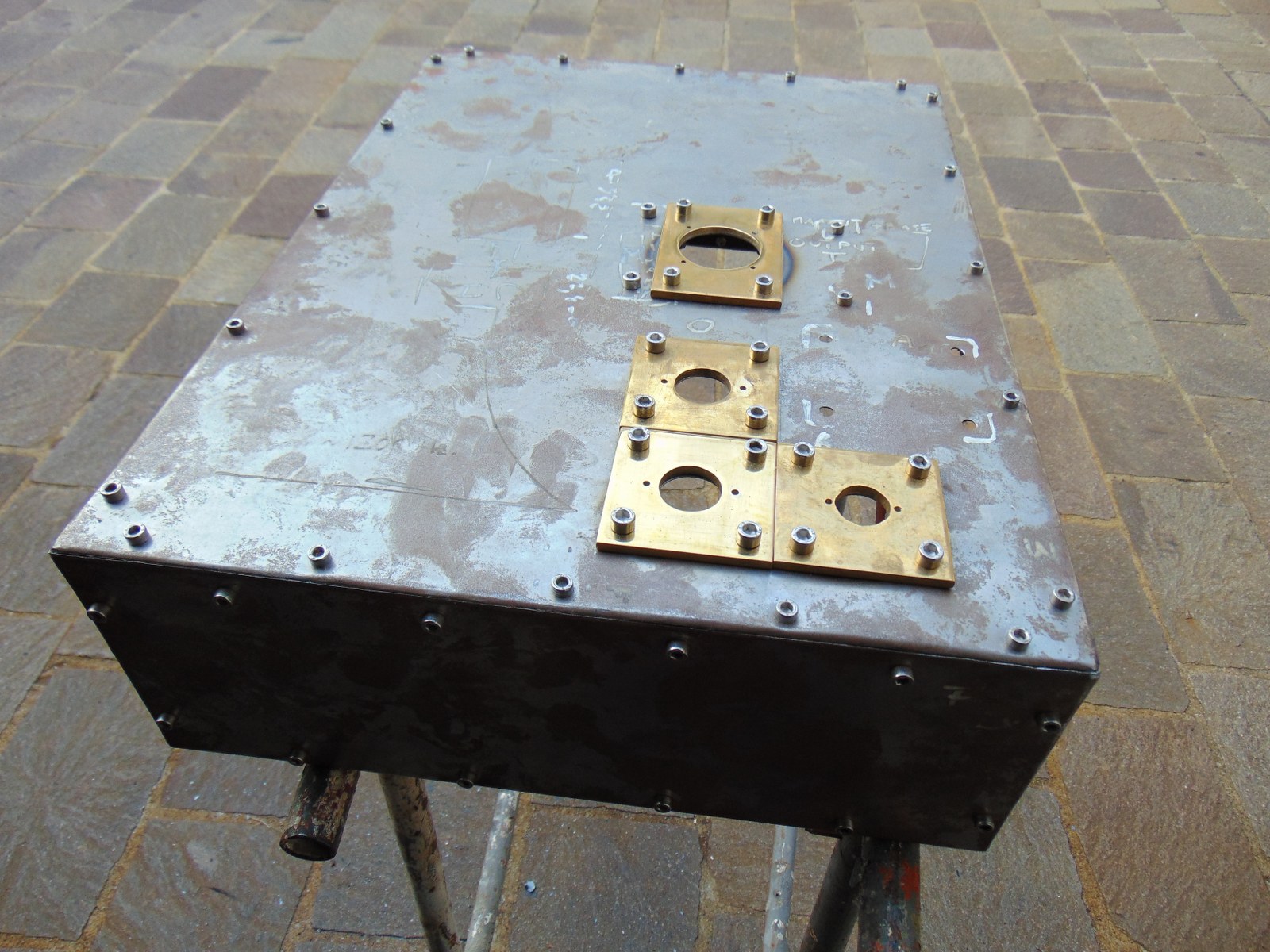
The 2 long hexagonal brass are only for picture, although I like them cut short.
Step by step this monster is on! I hope! :D
Attachment 14017 Attachment 14018
Attachment 14019 Attachment 14020
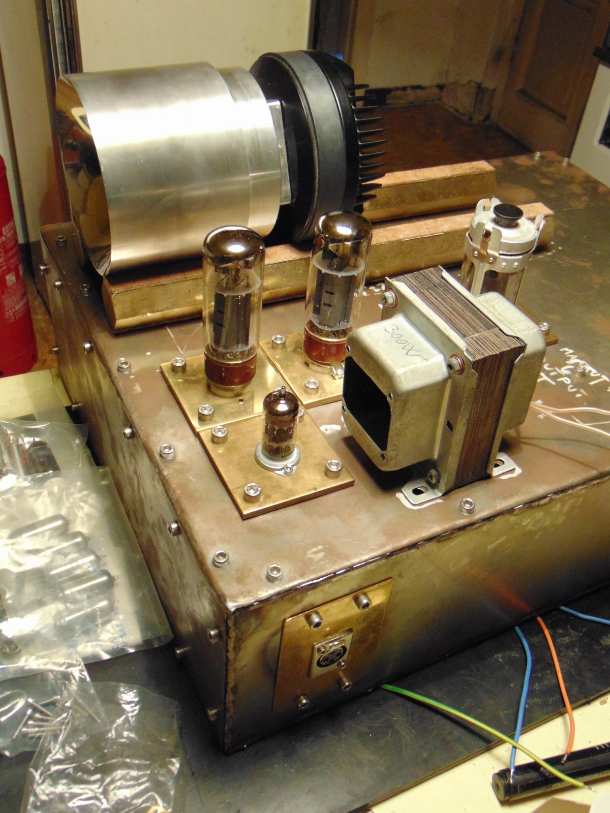
new front panel, as usual solid brass polished, I've improved layout of ammeter and switches for better cables position.
Next step, circuit!
Attachment 14092 Attachment 14093
HI all
... that's not a good evening, unfortunately!
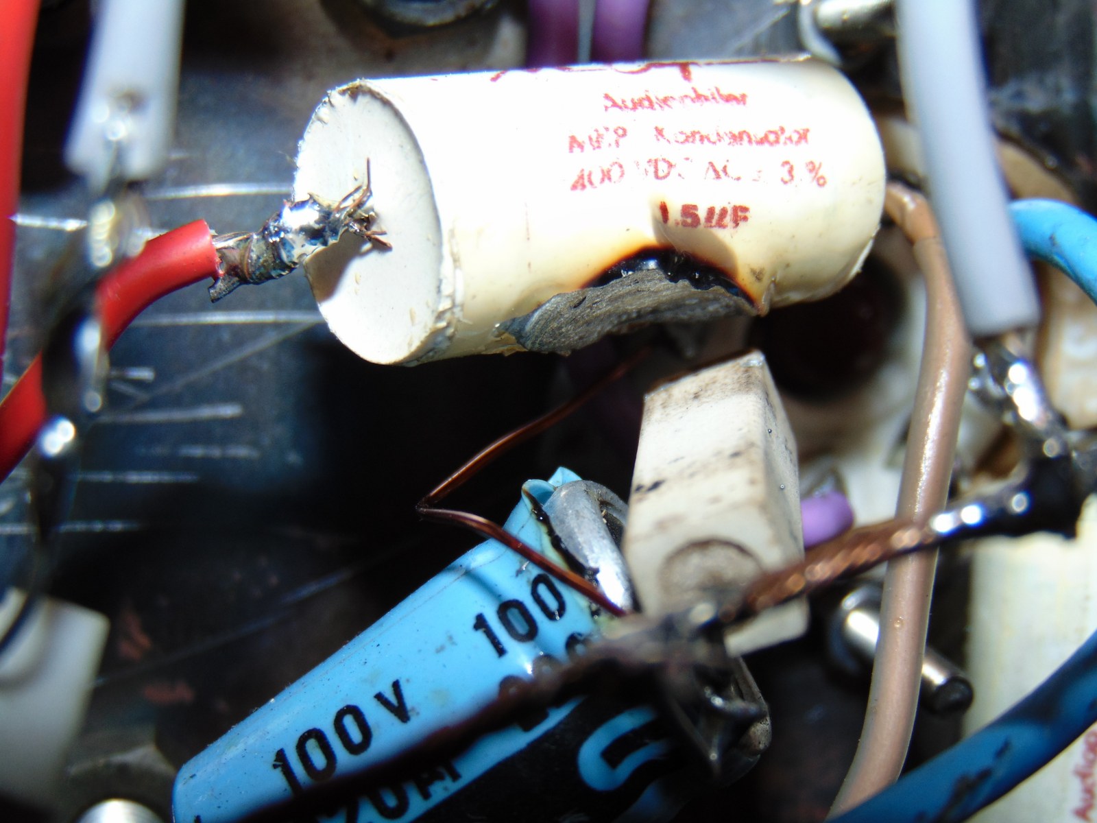
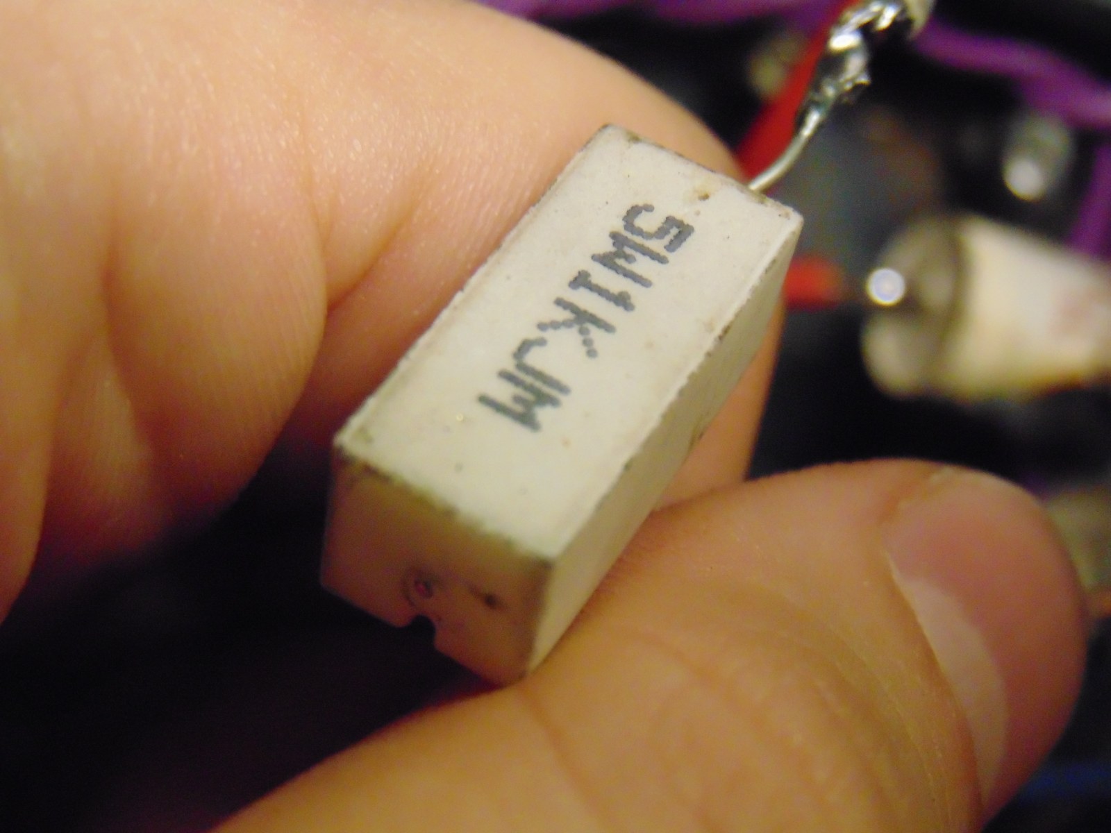
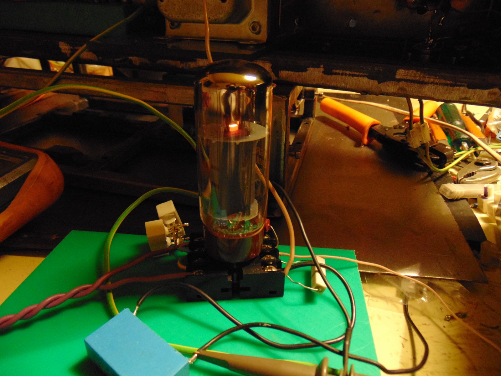
I've not seen that a crucial ceramic resistor broke its rheophore, leaving uncovered a part of the circuit.
Results: melted a mundorf capacitor, the outside of another cap, and damaged a resistor in only 10 seconds. There are also good news, flame is pretty big with only 50ma, imperturbable to environment, with or without semi-faraday gage. Shielded frame seems pretty good.
Autofire is more rapid than in the past.
Base is good, now I have to re-start tuning
Attachment 14219 Attachment 14220 Attachment 14221
Attachment 14222 Attachment 14223
Sounds like good progress! But maybe a "Bit under wattage" on the wire wound...and also way too close to other components. One thing about ceramic wire wound resistors is were the lead comes out of the ceramic. To much flexing of the lead and or too hot soldering close to the ceramic weakens the wire at the joint and they will break. They also make ceramic wire wounds encased in an aluminum heat sink you can mount to the chassis or a bracket.
For the foil cap you might try to find a replacement Spraque/Cornell "Orange Drop" epoxy resin type and can get them down to 3-5% if necessary. Pull the 100uf electrolytic and toss it...the bleeder hole is likely damaged from the excessive heat.
~PJ :popcorn:
Thanks for advice!
I did some calculation and attempts in order to understand better the trouble...
In summary:
-initial circuit run at 55v between gnd and cathode, with 220ohm cathode resistor are 250ma current, 3 times and something over normal operation. Not good, this working point destroyed first resistor
- I added a 2,7k resistor from power supply to g2 of el34, a little better situation, but Always too much current. 37.5v gnd-K, 170ma anode current. (normal working point "should" be 300v, 83ma with -15v Vg)
Components are new and show correct measure with multimeter.
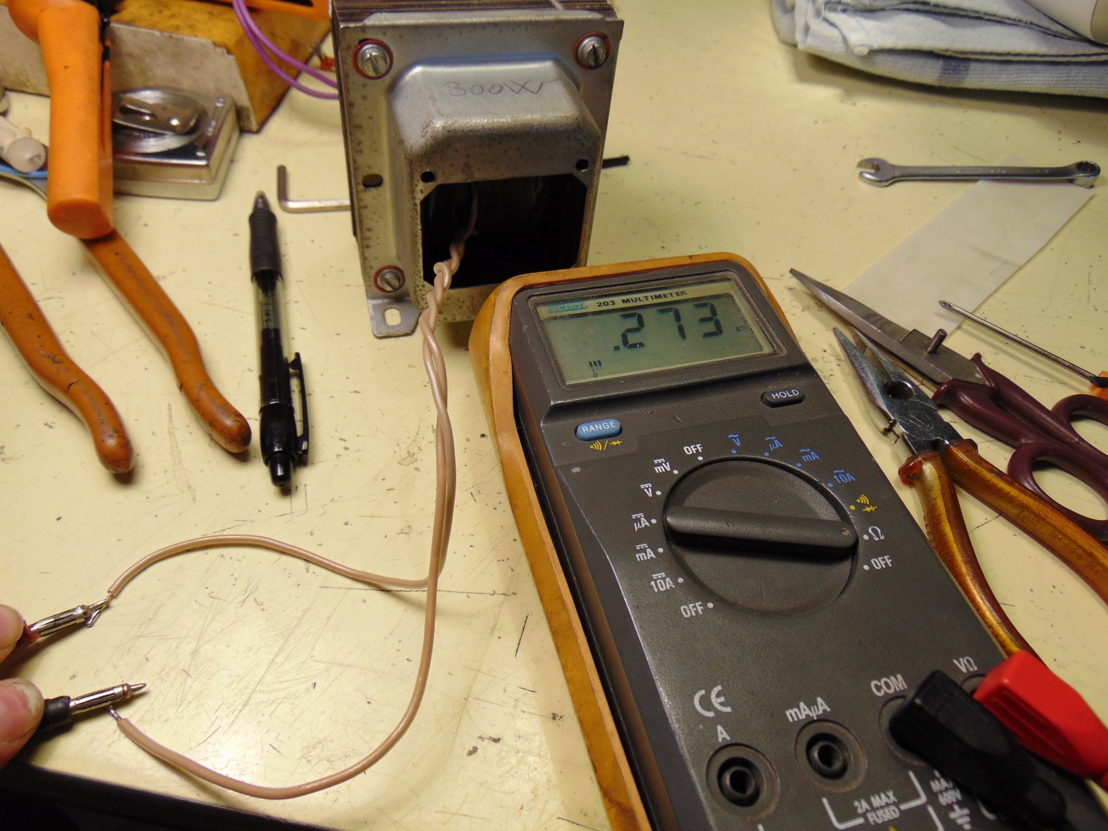
There remains only the anode choke, maybe the tube doesn't appreciate so much. Maybe turns of copper are not enough, and inductance need to be really higher, like in commercial product.
I got 2 way, for what I see:
- recalculate a coil with 100H of primary inductance. Lot of copper, this time I use lathe
- Try a high power alu resistor as you said, maybe 50w or more, and throw to the air some 25w. This way allows me to raise B+ for this circuit to 500v.
...everyday a new problem :cool:
New update
Second bad evening, due to circuit.
I was losing my head to look for the cause of the problem, last time I lost some capacitors and resistors.
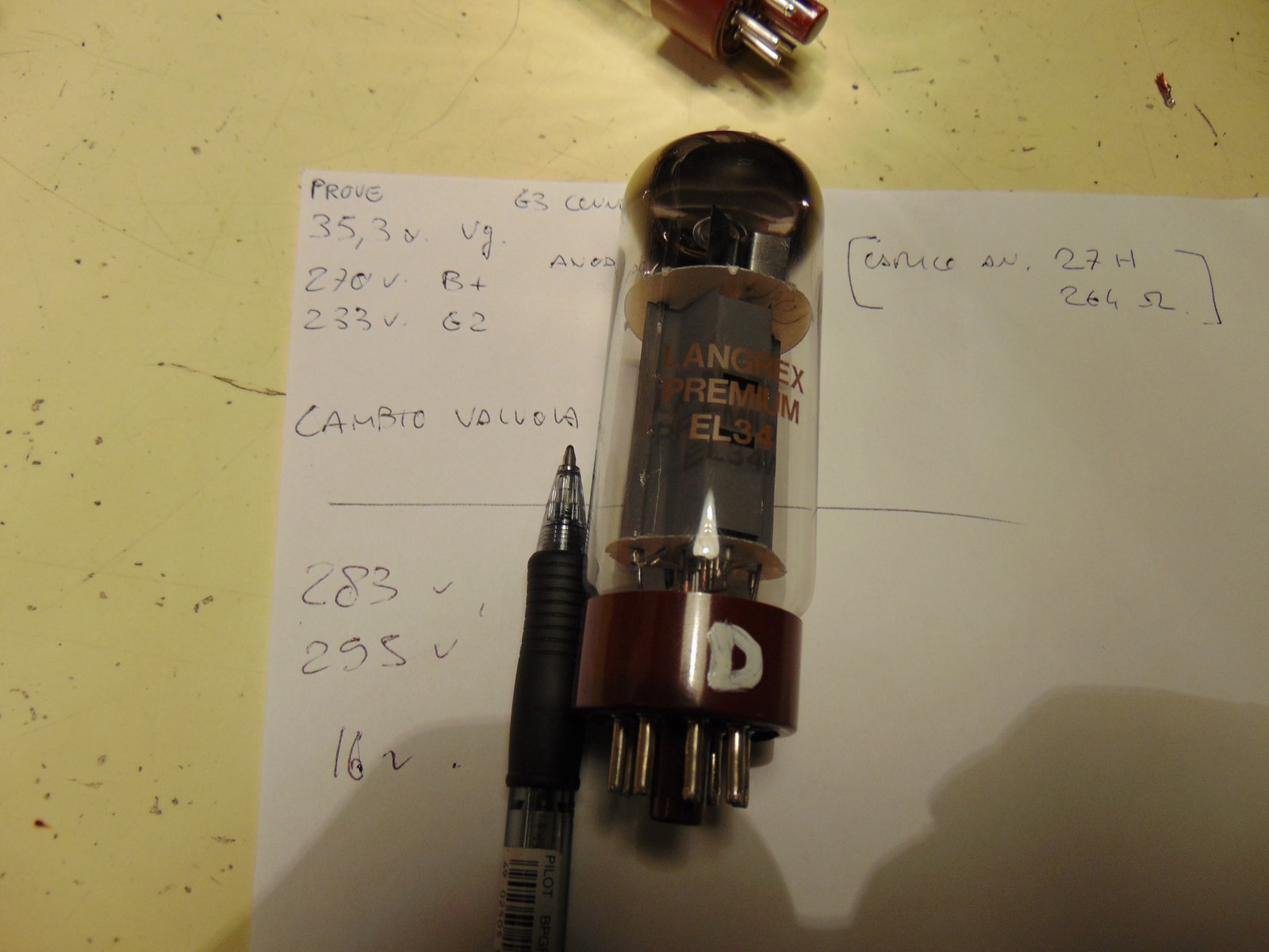
I found that one tube Langrex, "matched" quad, was faulty. In the same circuit, with the other 3 tube of the same lot everything is ok.
Bad tube runs at 35v of bias, +/- 160ma, current so high that powersupply suffered.
A couple of number:
- Normal value: B+ 300v , 290v on g2, 16v between cathode and ground, with 220ohm are 73ma of current. Good working point
- Bad tube: B+ 270v , 233v on g2 , 35v between cathode and ground, with 220 ohm are 159ma of current. This combo melt cathode resistor.
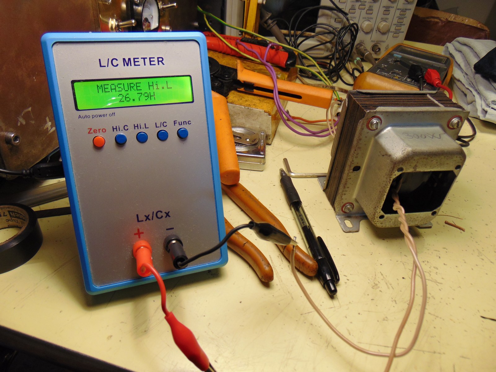
I modified also the anode choke, now 27H, and 273 ohm (+/- like a good output transformer) This thing has almost no influence on results, for now.
I'm writing a mail to Langrex, through ebay, in order to inform the seller about the problem.
Attachment 14265 Attachment 14266
Attachment 14267 Attachment 14268
Yup, a 5W resistor won't hold up to 13.75 watts very long...surprised nothing else went. Can't understand how a matched tube can be that different unless the cathode was shorted internally somehow¿ And the Bakelite base of that tube is singed! @!@ Hopefully your power supply is OK and they will send you a replacement?Quote:
-initial circuit run at 55v between gnd and cathode, with 220ohm cathode resistor are 250ma current, 3 times and something over normal operation. Not good, this working point destroyed first resistor
I'm assuming this is the same "Cathode Follower" circuit you showed me before. That's not a typical setup for a CF...Might want to take a look at that as I suggested before. Think I sent some links on them way back in the thread...if not Google it.
~PJ :popcorn:
Yes sir! Circuit is similar, updated for different tubes, in order to have more or less the same power of oscillator part, a good old rule with old transmitter, as I read :)
CF part is good as in the past,luckily something works! With 300v anode supply I get half voltage output to drive oscillator.
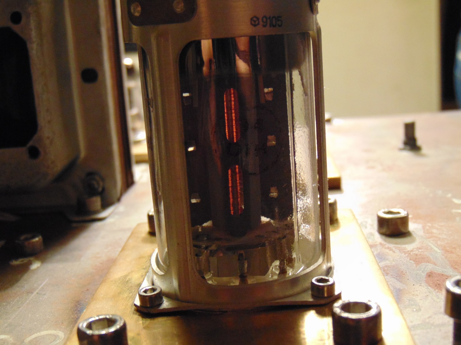
Not enough to bring the hell on earth, old good full flame with bright red plate near 200ma 1,1kv :lol:.
Still enough to achive a big, not extreme flame with still grey plate. I will play with coils and working frequency, even if I think that actual freq is good. Although I must say that this circuit performs better with tubes really hot.
The most spectacular working point tried, unfortunately I got no pictures (and maybe I never wrote here, because it was crazy) , was 1,3kv with ammeter in heavy over range, up to 250ma, with the typical sound of pointer against block. Small flame and pesky bright white from anode... That's why tubes hate me :rolleyes:
I hope ebay seller will reply Tomorrow, I think as you, some short circuit inside, or some strange grids structure, no signs on bakelite base, or visibile inside, the trouble should be inside.
I hope for a replacement, even if I bought a quad matched set ( I don't believe ), and I wonder how they can add a single tube with no matching reference.... I think I should close both eyes:flame:
Hi all!
I tried some circuit with fun tonight.
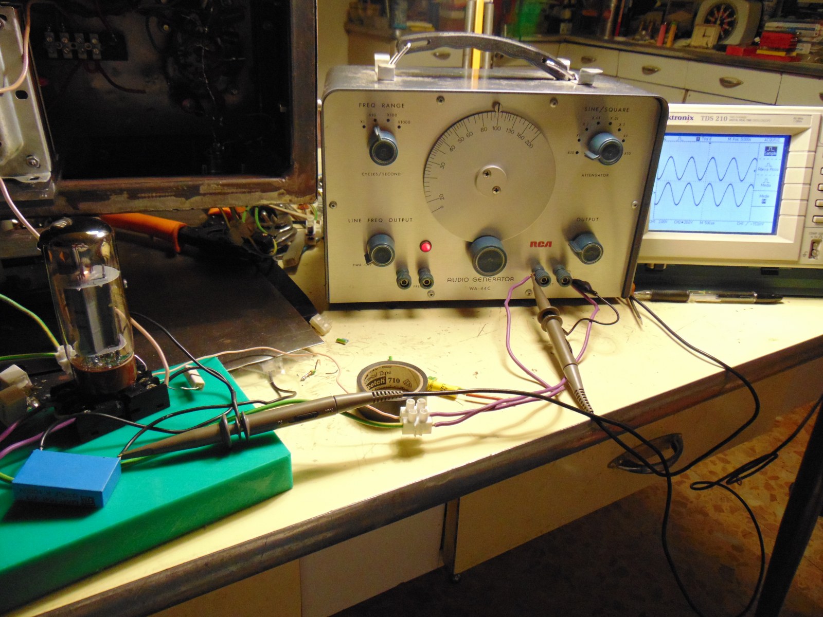
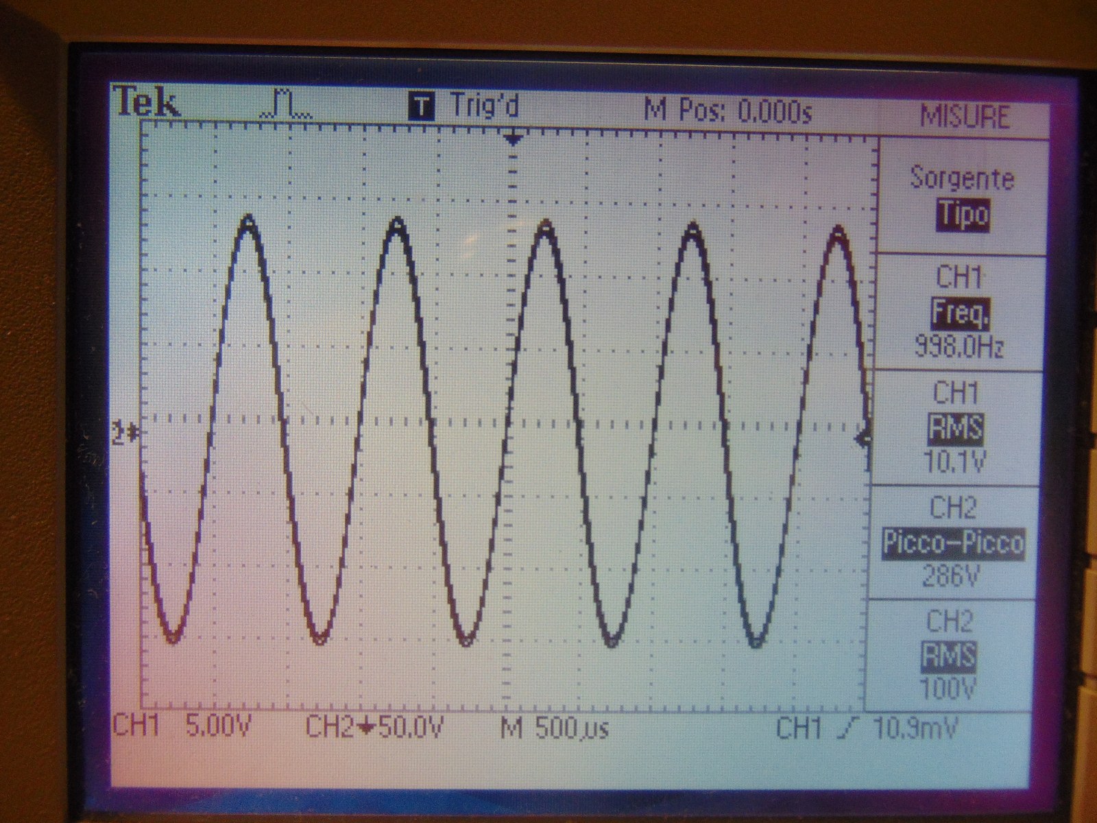
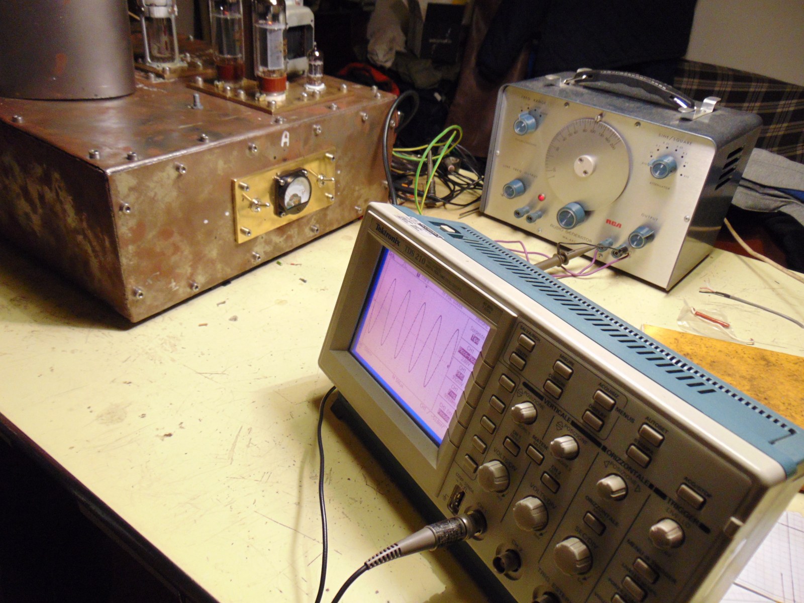
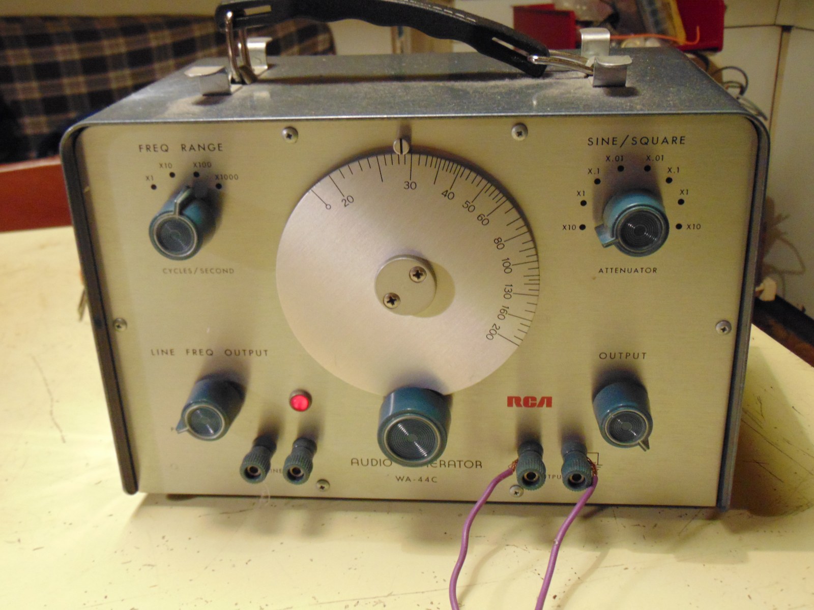
Because of many trouble with circuit, I wanted to test single el34 tube. I decided to make a fast amplifier on a relay socket, driven by old audio generator, capable of delivering 10v rms at 1khz, according to datasheet enough for undistorted output. El34 in triode now is good, but I have for the second time sockets-parts issues. Hope to find the cause soon
I will try in the coming days different bias and pentode mode, plus a better driver. Now tube is running at 52ma, with light warm cathode resistor, I'm on the right path
I also measured my ecc82 first stage, 35v rms output with less than 0,2v rms input, with a nice sine.
For the trouble with seller, he sent me a spare valve, which it is , more or less, a confirmation that there is no a real matching.
Attachment 14509 Attachment 14510 Attachment 14511
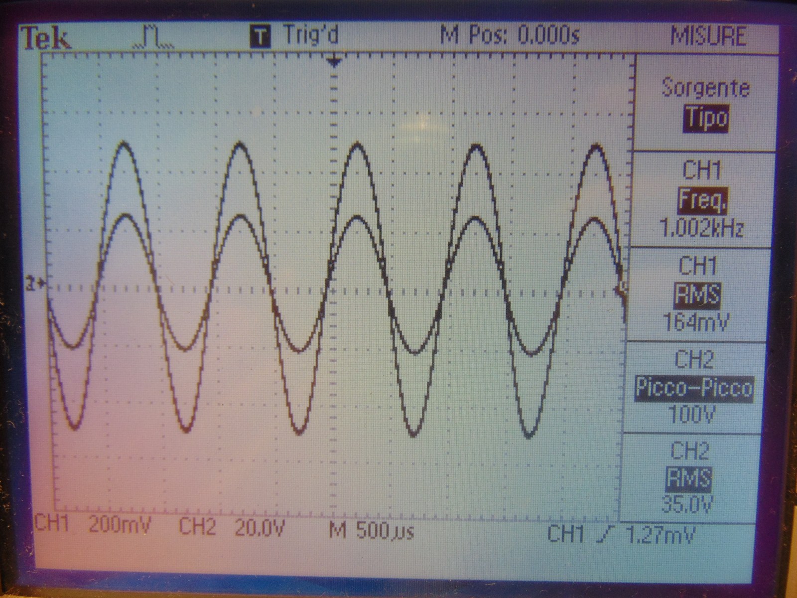
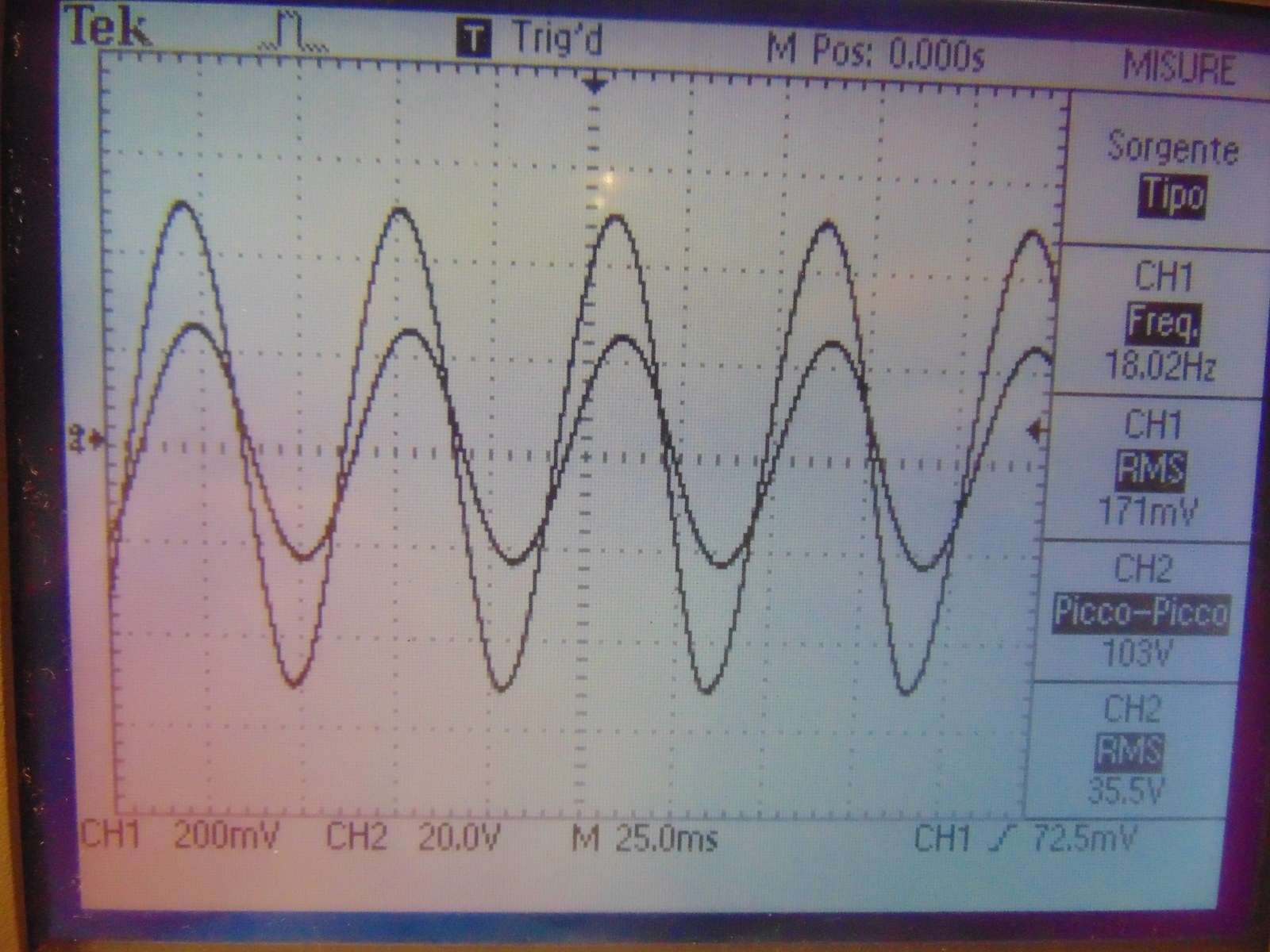
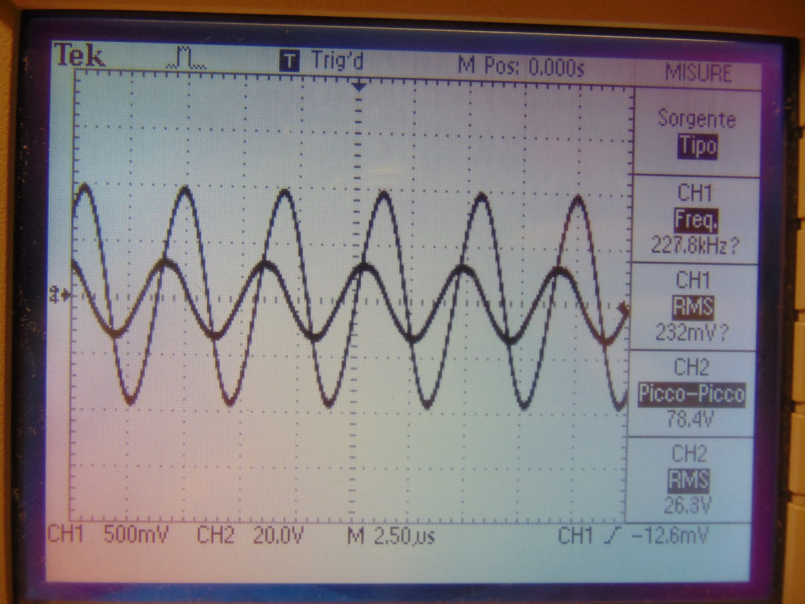
Ecc82 driver, last picture with 227khz :D
Attachment 14512 Attachment 14513 Attachment 14514Attachment 14515
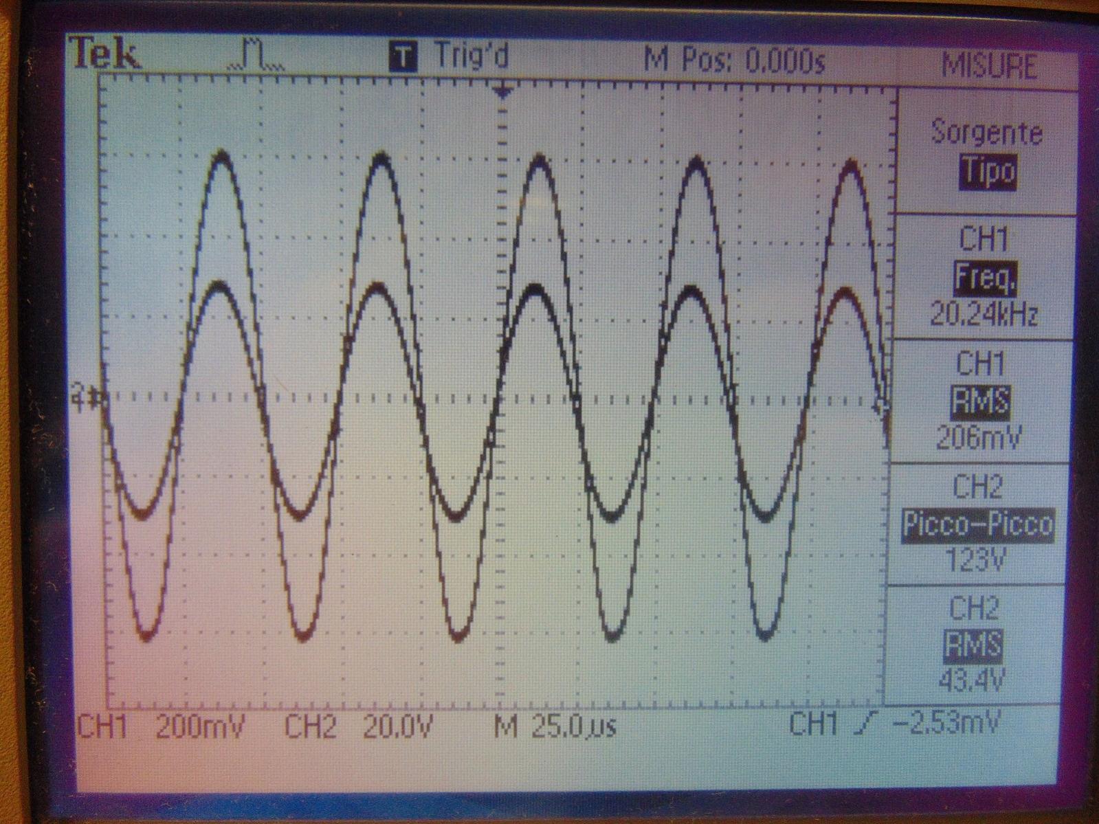
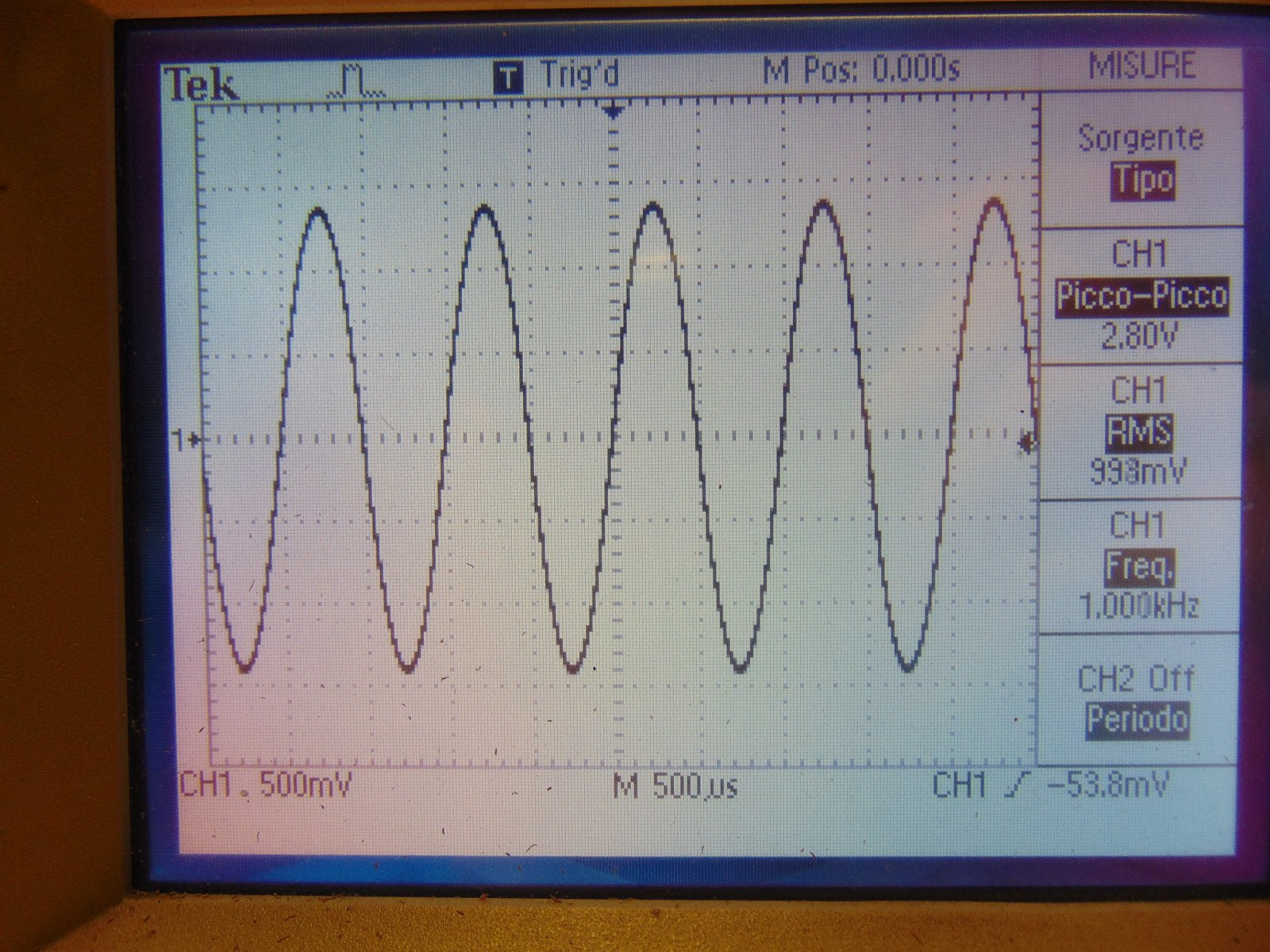
Hi Stefano, I'm not sure what I'm seeing on the scope...assume channel 1 is the EL34 and channel 2 is the ECC82 signal outputs¿
Is this the spare tube? We both new they weren't matching these to any real spec...its a huge deal to go through all of a production run and matching tube curves plus aging times and precision setups. That is precisely why they Cost so much. This was just Advertising to suck you in.
Those old 833's I had were matched by RCA and went for about $300 a pair back in the day!! These were on Ebay and don't even say matched pair Nor have gold Grids and definitely are Not RCA! But here is a real find on Ebay.
The sine waves look Very good at 1khz, spec voltages, but found it interesting that at 18khz channel 2 leads channel 1 and at 20khz it lags a bit? It appears that pushing the voltage on channel 2 is creating a phase shift...maybe slightly over driven. The good thing is even at 228KHz all you are getting is a ~90º phase shift and no distortion...that is impressive...be curious to see if it comes back to normal with a 35v on the ECC82.
You seem to be on a good path now, Congrats!
Until then, ~~ Keep your voltages nominal, your gain to 85-90% and your eye on the prize! Sparks will fly. :p
~PJ
Hi!
the tube is still traveling, Hope I will have in few days. You're right, pure advertising about matching, like many Others dealer. Next step on metal frame, I have buy belton, or anyway new high quality sockets, not chinese, something good, in order to have at least some more quality.
833a, love this tube!
Ch1 is Always linked to signal generator, ch2 on output of el34 in first set of pictures, and output of ecc82 in second one. You have a very good eye! I noticed that at 18khz output sine appears a bit translated, I will do a better thorough test to see correct levels at diferent sample rate. It curious too the 227khz test, I did for pure curiosity, but I did not expect this results ;)
Thanks for the advice! coming soon new tests!
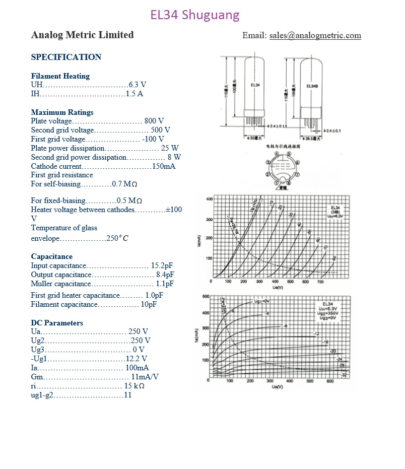
ps: this is the chinese datasheet of el34 tube. Ecc82 is a 6189w special quality, siemens
Attachment 14516
Hi!
Today I received the single spare el34 from Langrex, for free, it's a good seller for this.
I tried the faulty tube in new circuit, still gives bad results, I think I will test my new glock (arrival scheduled for this week) at shooting range with tube as target :lol:
I made some experiments with ecc82, single ended, one or double triodes connected. Both circuit give good results, for a se amp with el34, a single unit should be fine.
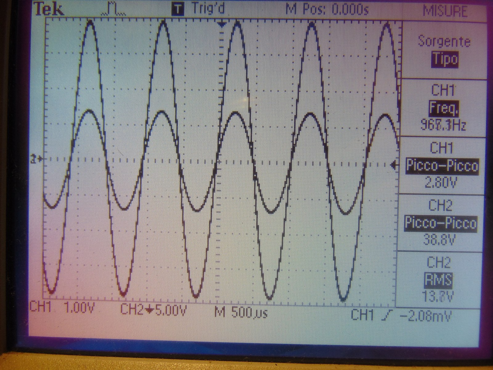
With 1v rms input (2.83v p-p), I got 13.7v rms or 38.8v p-p, enough to drive el34, maybe the right choice.
I tried el34 triode at 52 and 78ma, with same B+ but different cathode resistor. Unfortunately I can't find ceramic 8 ohm resistor as dummy load, I only see the anode amplitude for now. 52ma gives a better swing, and a colder rk, 78ma give imho too high temperature on 10w resistor and less amplitude. I will try soon with 8 ohm load and another output transformer
I tried also el34 in triode mode with good results, I think I will build an amplifier for my setup, this tube worth!
Attachment 14562
Ecc82 single ended, half triode
Attachment 14563
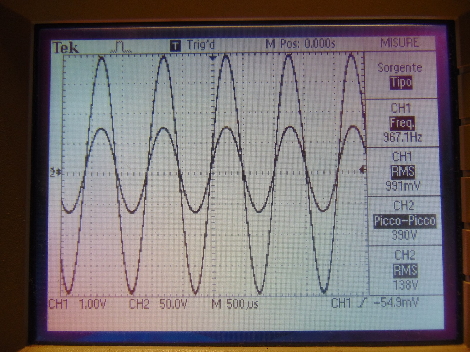
El34 triode, 19,5v bias, 375ohm cathode resistor
Attachment 14564
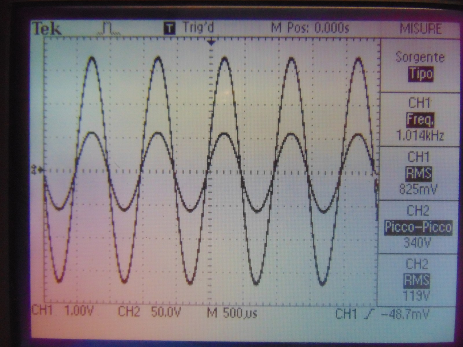
El34 triode, 16v bias, 220ohm cathode resistor
Attachment 14565
Looking Good Stefano! :clapping: Glad they comp'd the tube for you!
The 16v/220 KR seems to lag just a skosh but the 19.5v/375 KR leads a bit more than a skosh...might try a 330 ohm at the 16v. That should put it at 0º...and the amplitude looks better at those lower values. It should be plenty of gain for your need but will depend how well you couple it and the quality of the oscillator/HF circuit.
Not sure what to say about the 8/10 ohm...more henry's might help???
Keep up the faith and the force will be with you! Great work!
~PJ :popcorn:
Hi all!
Big update this time!
After a night, my plasma speaker is running!
Trouble as usual:* 2 new capacitor purchased from an Italian shop (the same of noval defective sockets).*
Few words about, I did a fast run, no hum, no noise, good and loud sound. The shielded frame works perfectly even if I soldered fast some components inside.
I have to try for my curiosity the range with microphone and software, 1khz is loud, maybe 2khz is the usable fq.*Finally I can tune the circuit, there is lot of work to do, tubes run in full safe operation mode now, I can squeeze more power from both*hf unit and modulator (remaining in datasheet range).
Next attempts:
- pentode mode amplifier unit
- raise driving voltage of oscillator at maximum (datasheet)
- try higher mhz working frequency, different coils and cap (flame is fully silent)
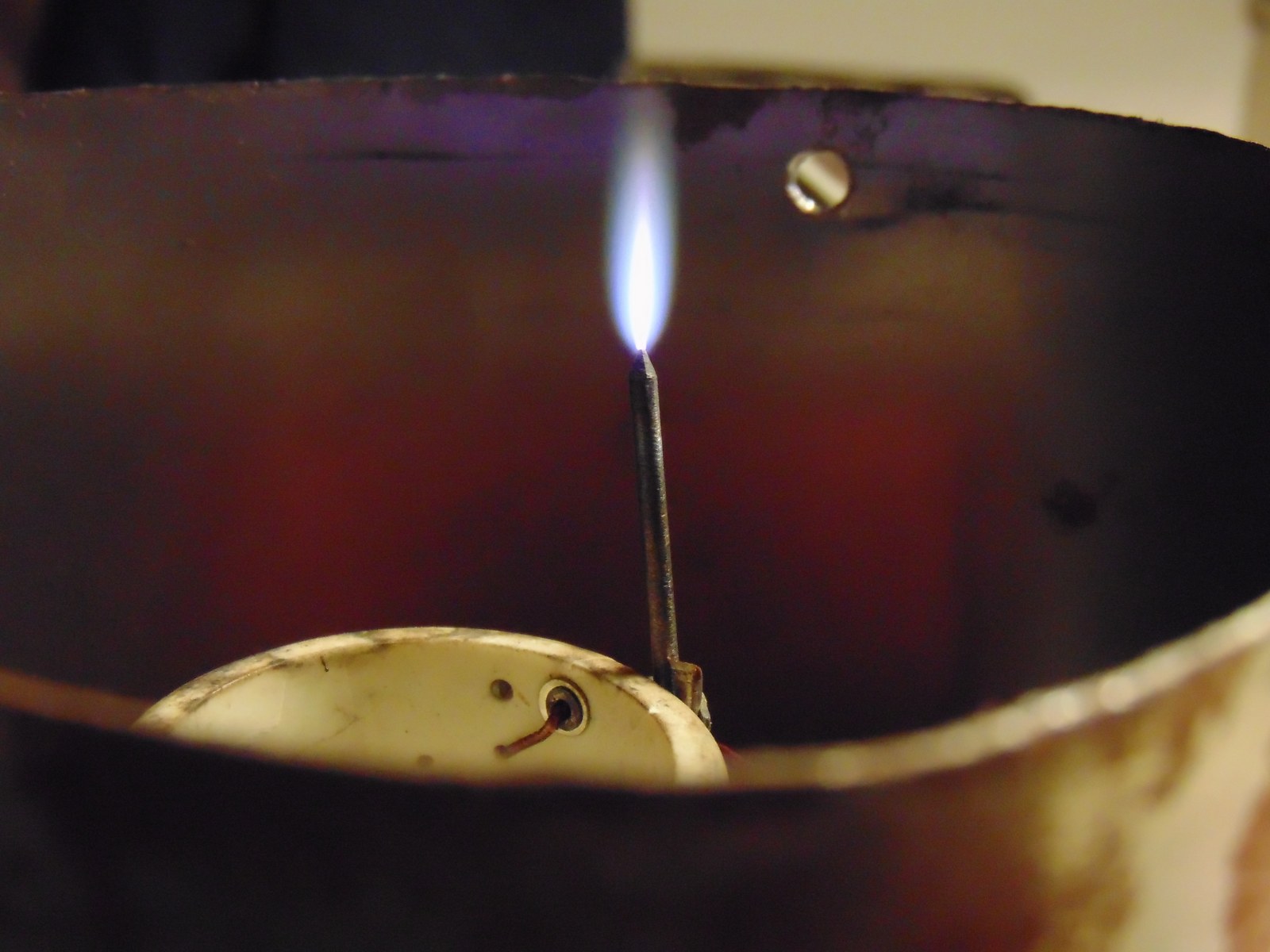
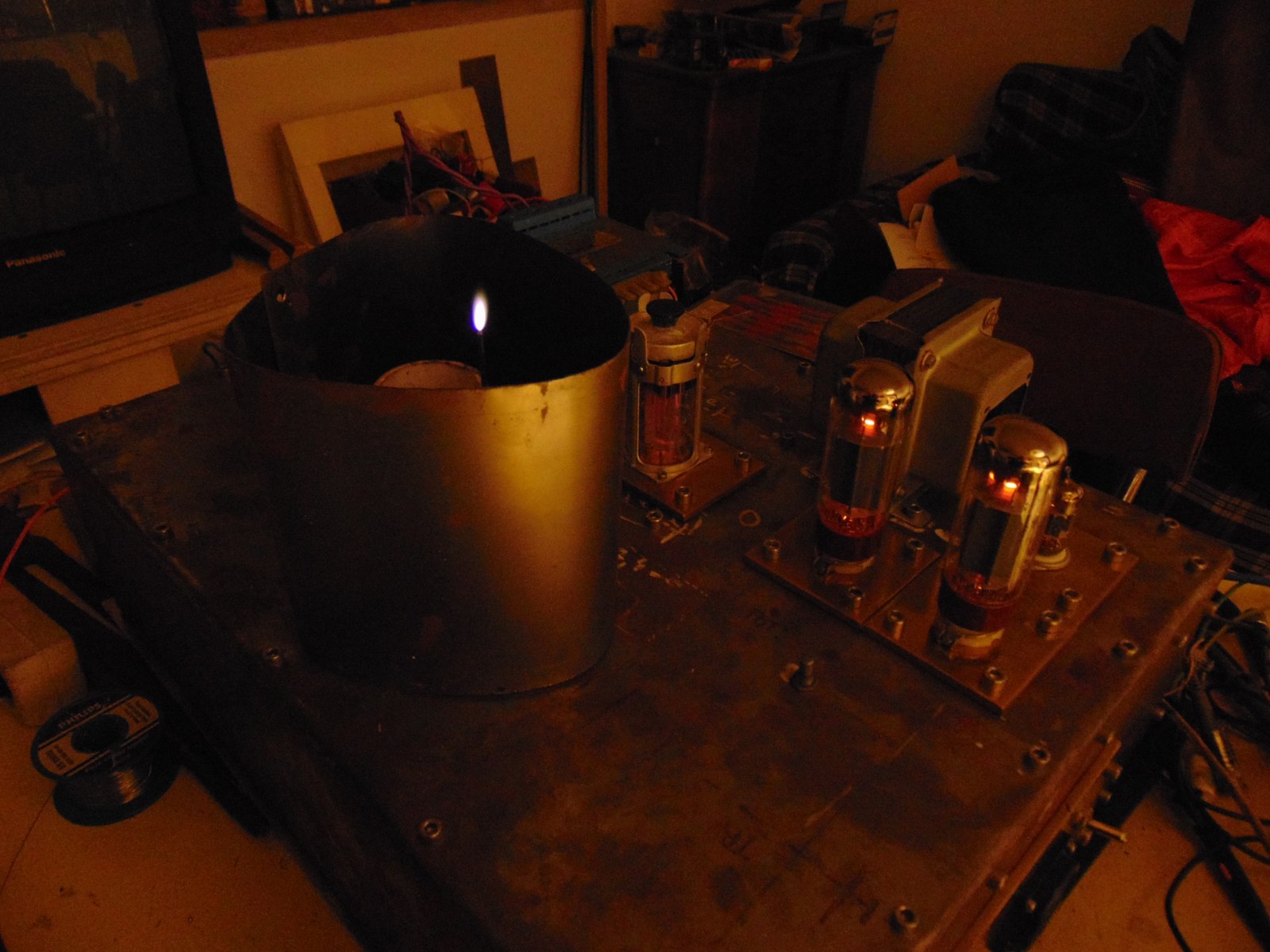
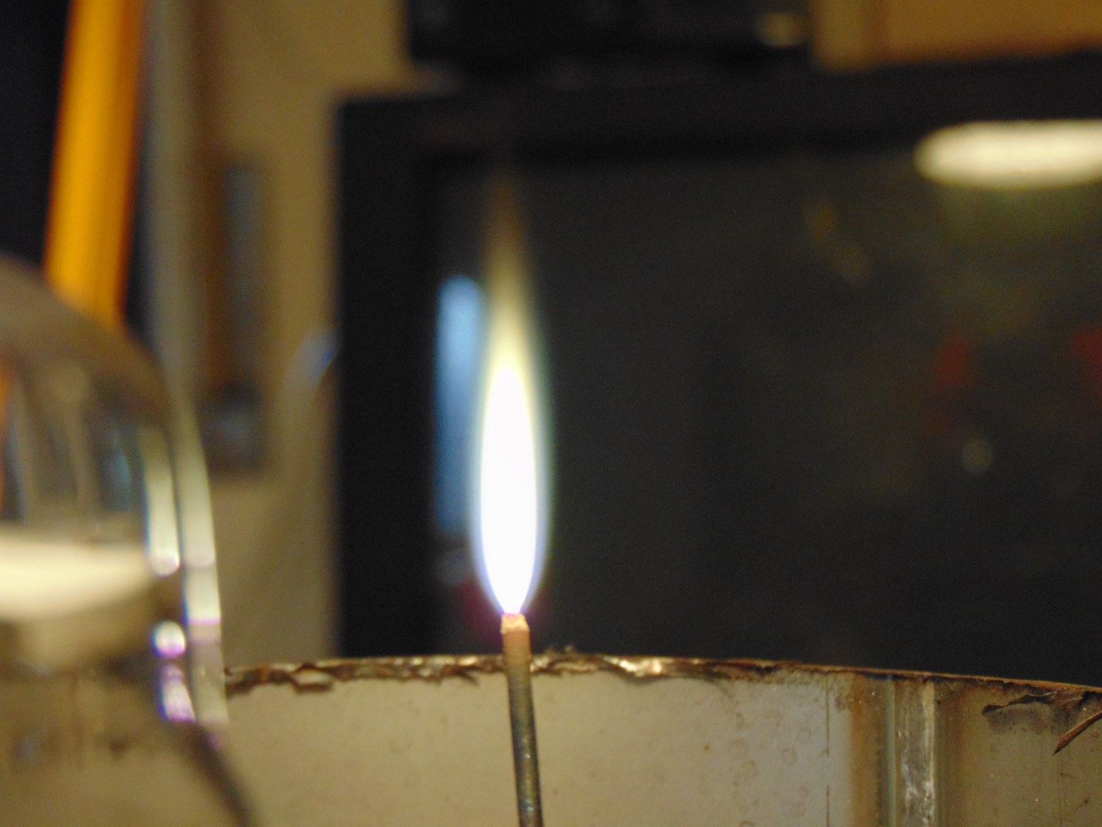
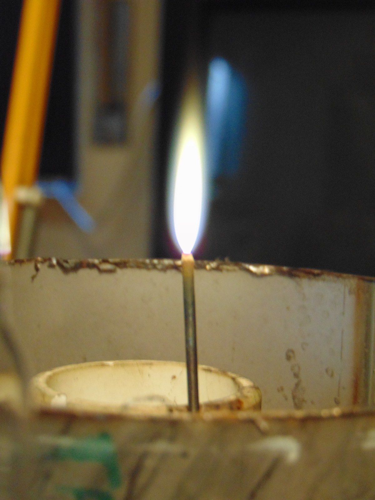
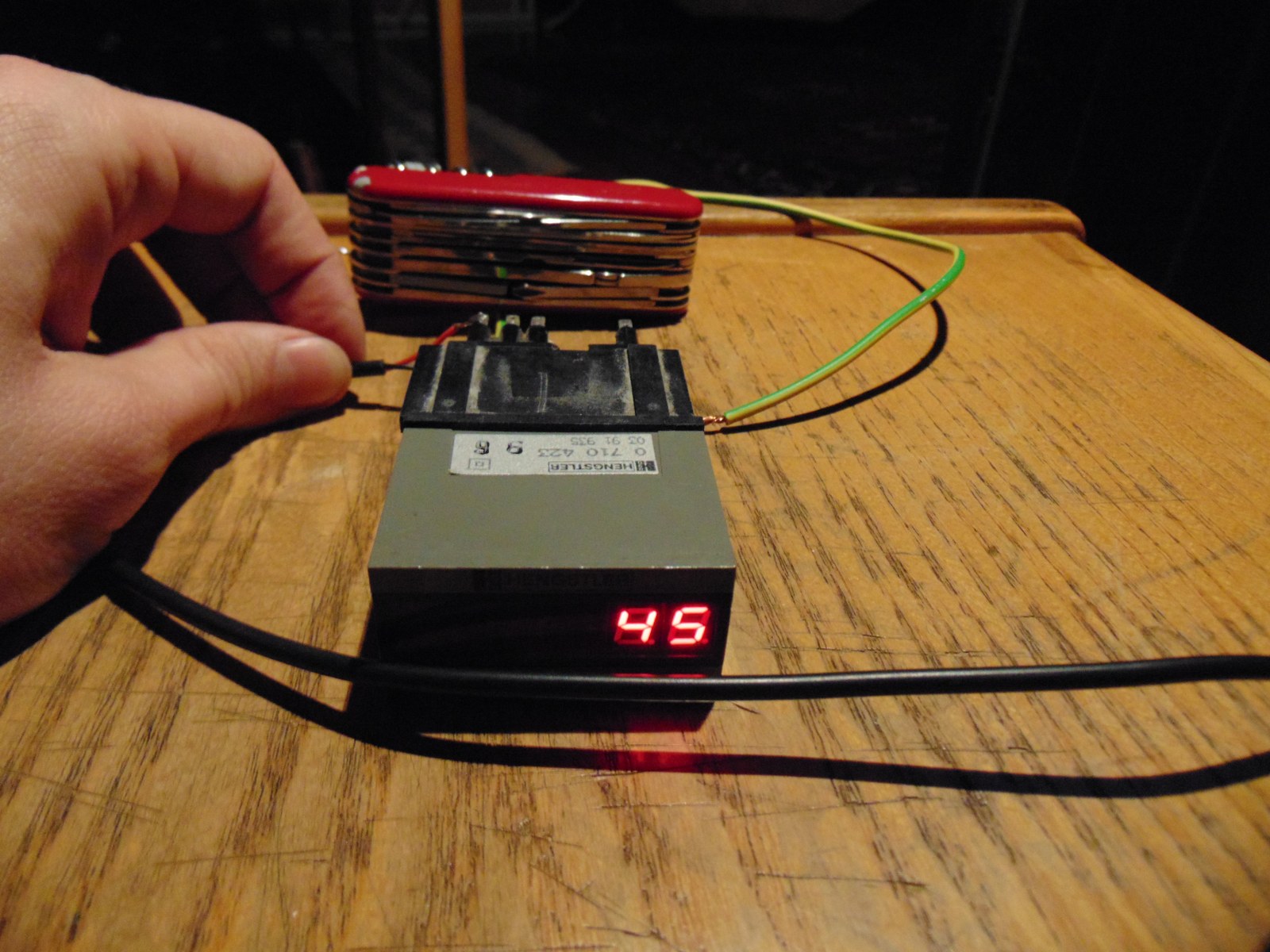
With my new modulator circuit flame runs from 10 to 20mm, from 50 to 110ma at 1kv.
No red plate, no red grids, power transformers run at low temperature.
Autofire is Always running, no strange behavior noticed.
In few words: circuit is stable and well running, now is labor limae!
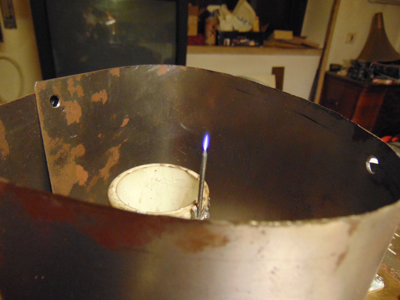
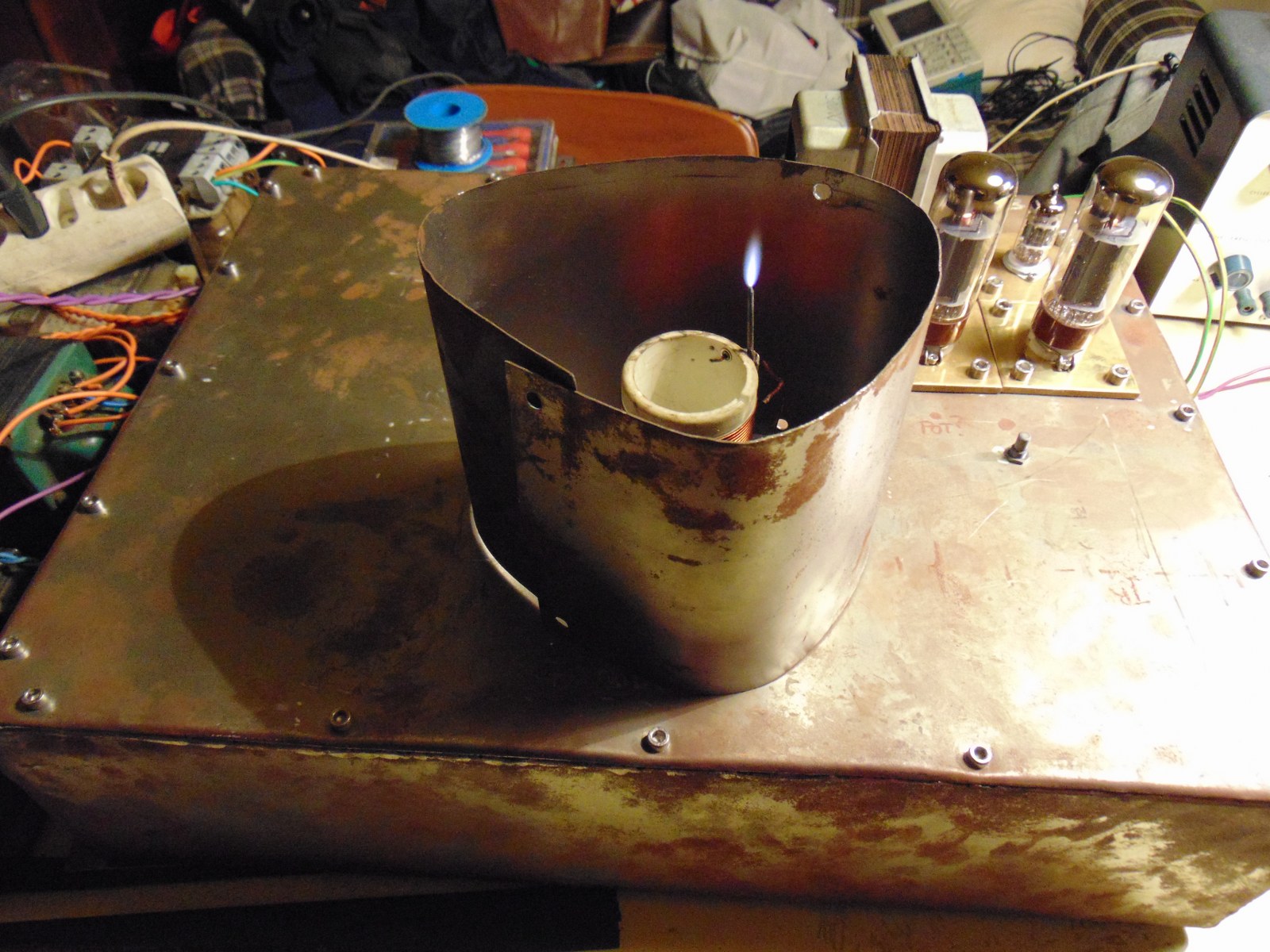
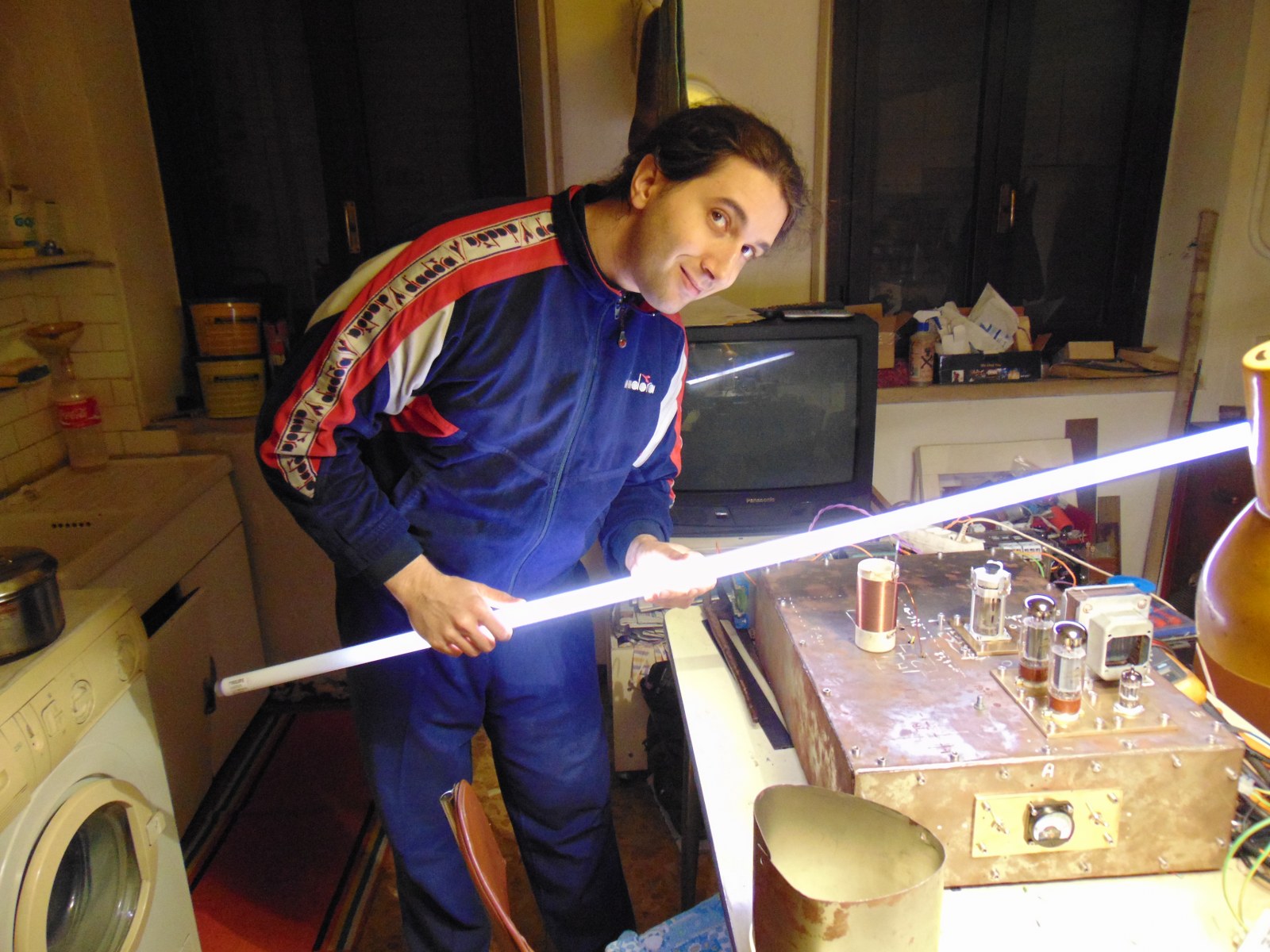
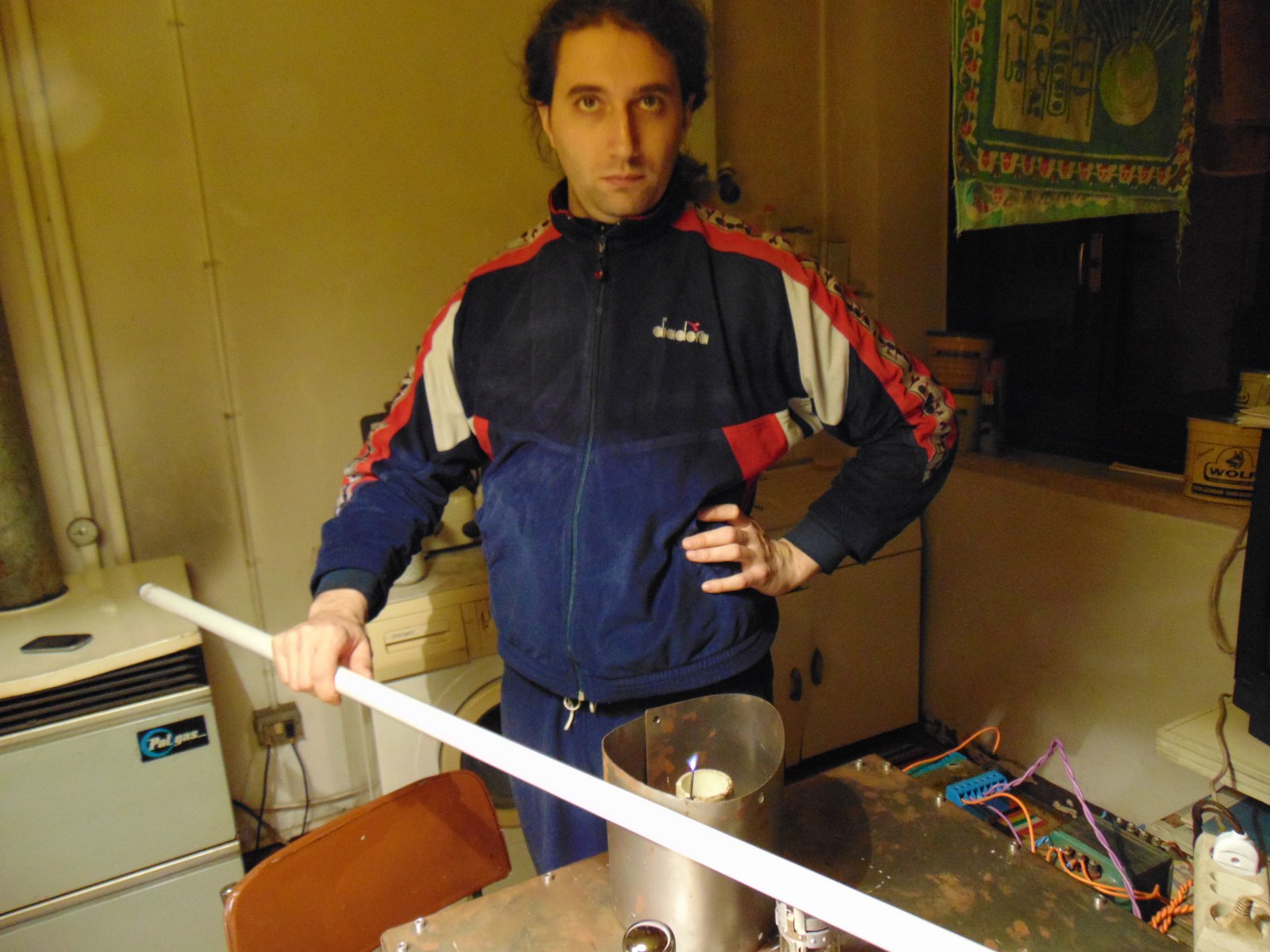
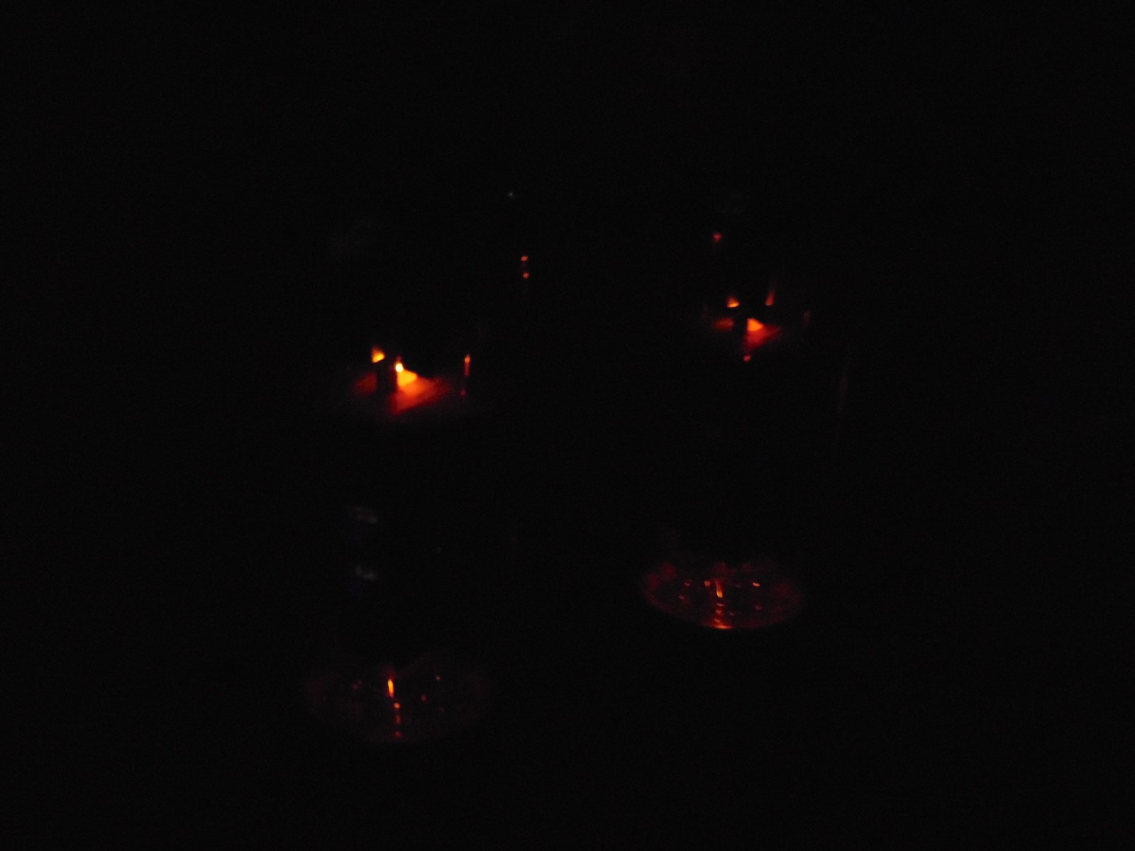
For comfort I used semi-faraday gage, it works perfectly, see differences in pictures with neon, at the side is not possible to fire neon, even the rf emission on top is really reduced compared to full air coil.
Attachment 15347 Attachment 15348 Attachment 15349
Attachment 15350 Attachment 15351 Attachment 15352
Attachment 15353 Attachment 15354 Attachment 15355
Attachment 15356 Attachment 15357 Attachment 15358
Attachment 15359 Attachment 15360
Been a bit anxious to know how you've been doing with this great project. Excellent news and progress Stefano! The Plasma Flame looks perfect and if it's quiet and tubes running as indicated, that is wonderful. Was that flame at 1KHz? Your makeshift cage also seems to be pretty effective. Are you still planning on running it horizontally into your horn? How are the ozone levels with this plasma size?
Small advice about raising the input voltage to max data sheet. Typically you would want to run it at about 80-90% to stay out of distortion range and not generating too many harmonics. A test at max is fine but running should be below.
A little confused by this...is the flame not completely silent now? What frequency are you running at now? Not sure a few MHz will make that much difference for all that work.Quote:
- try higher mhz working frequency, different coils and cap (flame is fully silent)
Very happy for you and the progress you've made...a long way over a 18 pages and a years work!!
Till The next installment, :popcorn: ~PJ
Hi PJs!
Thanks! Yes both the pictures of flames are close to 1khz, I've seen that with full flame there is some more fuel to low frequency and a bit more volume (but not so much). Makeshift cage is made from 0,8mm steel, a scrap folded with no glory :D , but really effective looking the neon result, I'm impressed!
Imho ozone now is not so much, even at high flame, you can only smell a little with nose over flame, in normal room I don't think it is a problem.
I want to make quartz chamber as the initial idea, coupled with a 900-1000hz cutoff horn, that means +14-15db of spl, plus the full degradation of ozone.
Max g2 imput of oscillator is 250v, now I'm running at 160v, near 65% , I'm not so sure about giving more volt, can be useful as study, but not for sound maybem you're right about distortion
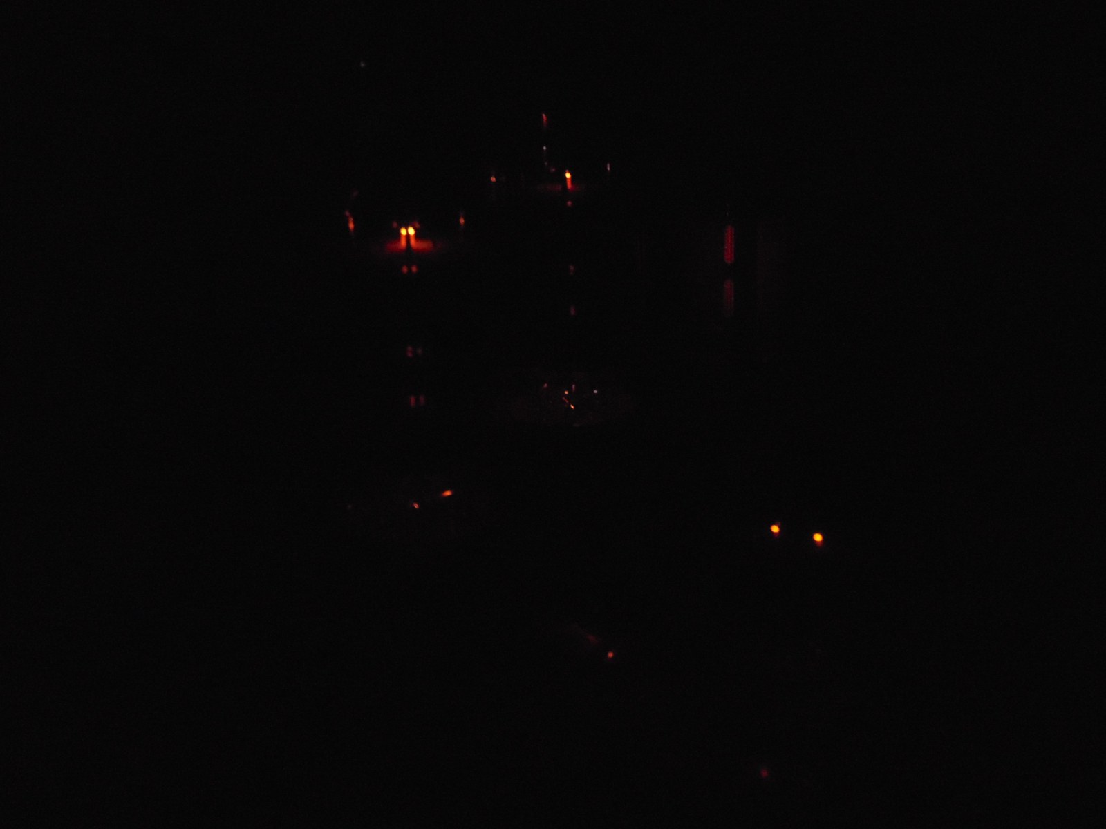
Flame is completely silent and with a good shape,now freq is 12mhz, I want to try 25\30mhz, flame for sure will be shorter. I want to make this experiment to see what will happen to sound, honestly I think the actual frequency is good enough.
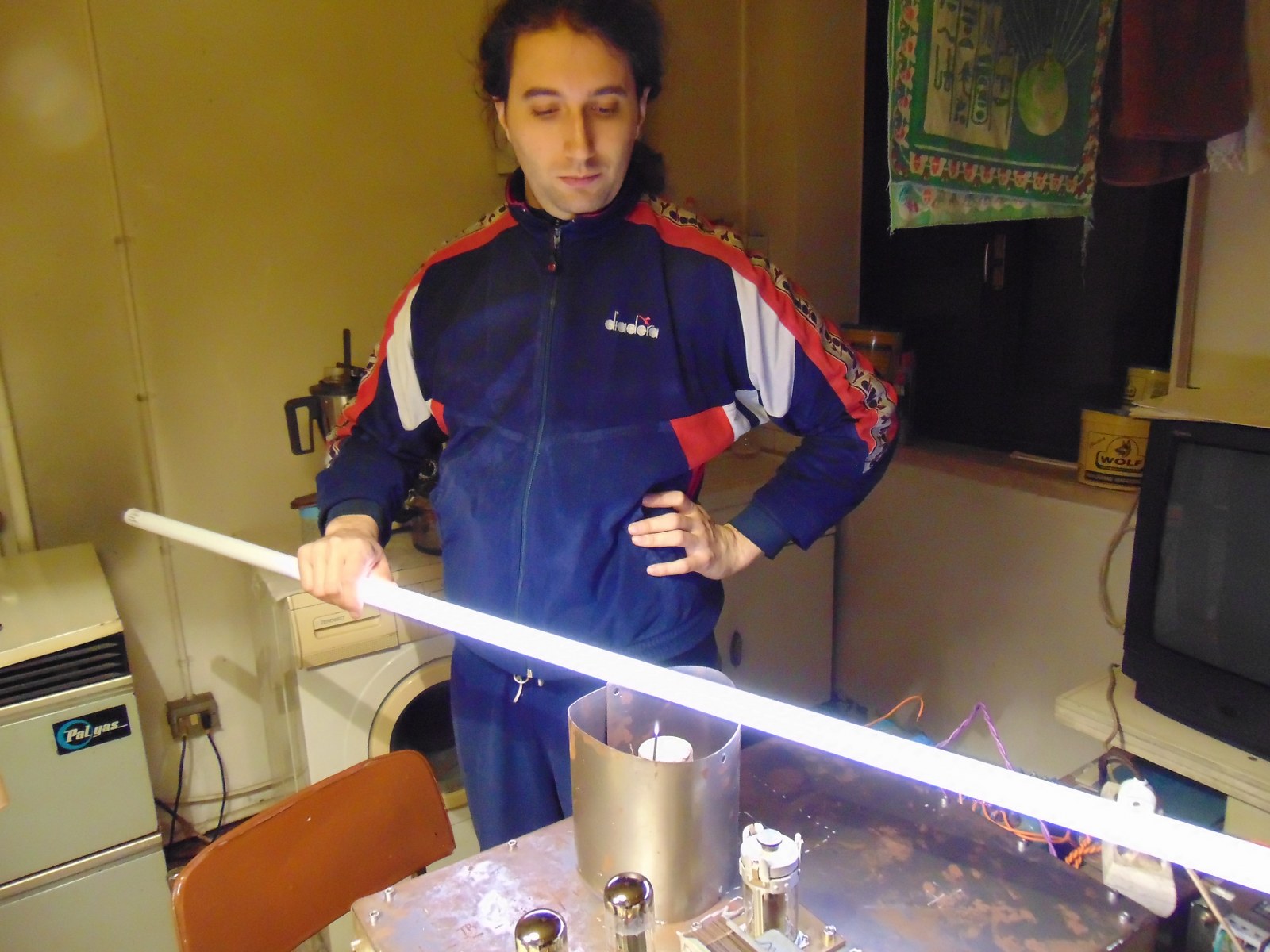
I'm thinking about position of flame, orizontal horn for sure, with vertical coil and a sort of ceramic connector for tungesten - copper wire, I have to found some good old isolator and Mount it over a teflon round bar.
I'm thinking for other options :rolleyes:
Hi!
Something interesting today!
No tech or dissertations, only video and some feelings about plasma.
How does it sound? Sound is amazing! (not because I built it :D )
Circuit is running as fullrange, with no input filter, not the best condition for music, but very good for test.
There is some clipping at full volume probably due to presence of bass, overdriving the el34 amp.
Highs and mids are something different from normal diaphragm speaker. Sound pressure is high, with a good aluminum horn and a very good coupling I bet this circuit can face my sensitive fullrange system.
I'm at the beginning, circuit is running in safe mode, I have many things to try and to adjust.
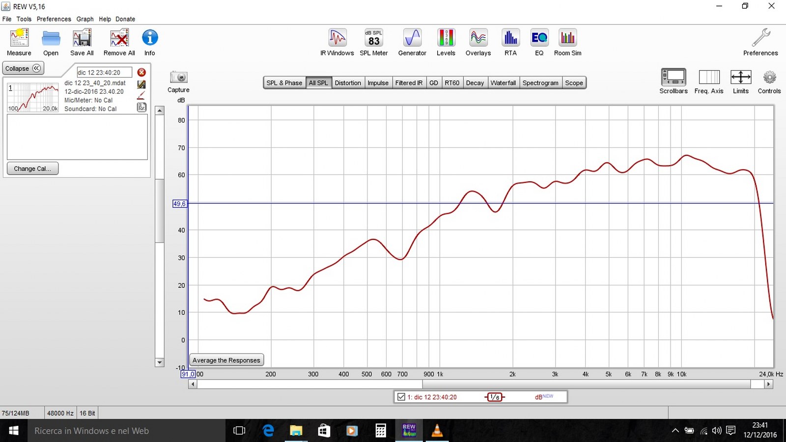
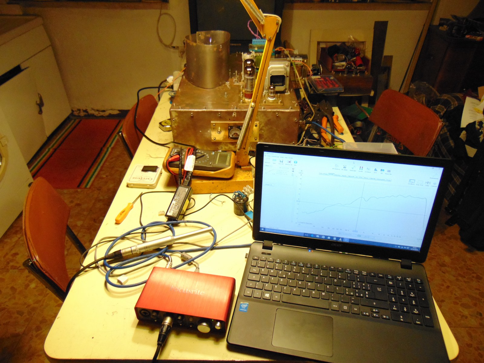
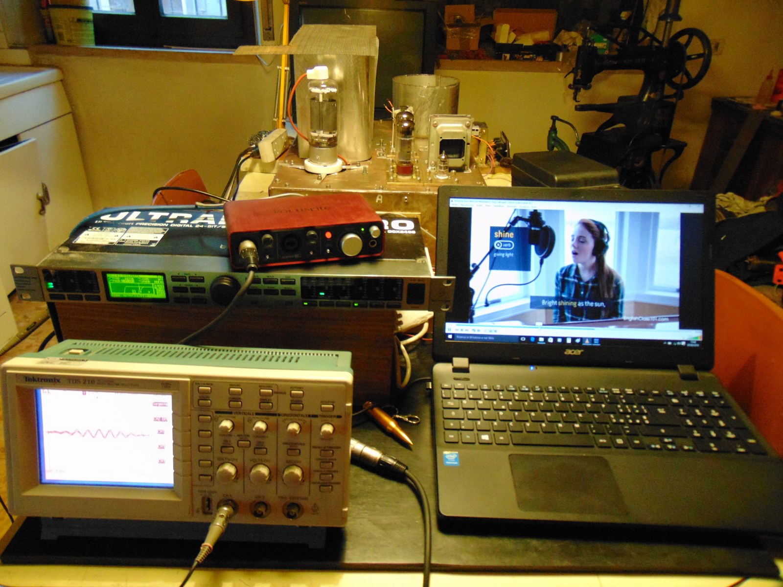
I did a fast measurement with Rew in the room, just to know more or less how this thing works. I see a very good response from 4k up to 20k (sorry but I have poor microphone, it reaches only 20k) I hope with some ideas I have to gain 2k range. It's still impressive how much sound can produce at 1khz, considering size flame and driving.
The funny thing is that it took me so long to make running the circuit hot (do you remember red cherry plates?) , consuming lot of current, and now I got the same flame size with half clean current!
I post 3 videos, recorded with camera, not best quality but better than nothing :rolleyes:
https://www.facebook.com/stefano.ran...1212254124884/
https://www.facebook.com/stefano.ran...1212406048682/
https://www.facebook.com/stefano.ran...1212316966455/
Ps: flame in orizontal is perfectly straight
Attachment 15445
Attachment 15446 Attachment 15447 Attachment 15448
Attachment 15449 Attachment 15450 Attachment 15451
Attachment 15452
:clapping::thumbsup: Actually quite remarkable considering the simple protocols for these tests and you were streaming audio from a video probably in MP4 format. It doesn't surprise me the DB levels that you achieved, with good clean interfaces between stages at proper power levels. However I noticed these were run without running the Calibrations on your sound card, and ECM8000 mic they are likely skewed a bit. For me the Ears have it in the long run as to the f response once you take a look at some detail in the RTA.
I can't remember if your frequency generator has a sweep function but that would be where I would be heading once I calibrated the sound card and mic. If it doesn't it might be available in your REW software and I would also run a 24 octave RTA test with the mic at 1 meter. Once you take it through those places I would probably use some solo classical piano to get a feel for what it can do in real life. The celtic was great to hear but violin strings have some interesting harmonics for this level of testing, imho.
Personally when I test speakers for my ears and a room I use a vinyl of Liz Story's Peace Piece not only because it is beautiful (imho) but the pacing and individuality of the notes on her Steinway give you a clear indication of what the speaker/system can reproduce particularly the last bar or so.
If I may pontificate a bit more :embarrassed: : Consider that you have built a wonderful analog tube amp with tenacity and verve that feeds an incredible plasma speaker you designed and Built! :hattip: But when you feed it with an mp3 or 4, these are nothing more than an "Interpolated" version of an "AC" audio signal (an algorithm to simulate the sine wave). For MP3's anything above 192K begins to add artifacts and at 320k about 1/3 of the signal is artificial. I was shocked a few years ago when I developed a circuit that would decode a 19.2Khz (narrow BW ~±.2Khz) signal from an audio MP3, that I had to build a 4 stage modified Butterworth filter just to get it out of the "Interpolation". Beyond 192K sample it started to fail because of the artifacts introduced. Even adding stages didn't really help. The Scope doesn't lie and 24 octave RTA shows it on a grand scale. None of this changes the fact that it is a Digital age anymore but even AAC Lossless has some, and imho Wav/AIFF is the better way if possible if that is all you have to drive it musically...keeping in mind any conversions are just interpolations! Best of all, I recently heard that England is experiencing a rush back to vinyl (Yeah)! If you could drive this from a turntable I bet you would be surprised by what you hear!! Nuff Spew. :p
Terrific Job Stefano, my hat is off to you....Congratulations Sir. On the downhill side now!
Thanks for sharing. ~PJ :popcorn:
As a newbie with just a few posts under my belt I was directed to this thread as an example of how things can take off on here. I read the first page and saw that there were 18 more so I skipped to the last one to see how things were going. I'll try and catch up with the rest later, but it is just to easy to spend too much time on the net reading interesting stuff, I like to make interesting stuff and finding time for both is always difficult. I work slower now than I did 55 years ago.
I notice that I have several things in common with some of the people here.
Stefano, I share your enthusiasm for motorcycles (you may find my web site and Facebook of interest). I live in Spain and suffer the same problems as you when it comes to buying what are regarded as industrial tools. The shops here don't sell to private people. Fortunately, I make 5 or 6 trips each year to the US, mostly to race but sometimes for work. When a trip is coming up I scour eBay and have stuff sent to a friend there. I have enough air miles to be allowed 2 free checked cases of 23kg each. If the trip is for a job then I fly business class and get a luggage allowance of 3 bags of 32kg each. So I usually come back loaded with hard to buy stuff here.
C-Bag (you must have a real name?), A mandolin player I see. that reminds me when I was between 8 and 11 ( I know that from where we lived at the time) my mother decided that there should be another musician in the family, she played the piano. My elder brother worked away from home and nobody ever expected much from my younger brother so I was nominated. The mandolin was chosen as my weapon. We lived in a country area of Australia then with no music teachers within a large distance so I was enrolled in correspondence lessons. The lack of a real teacher and my total lack of any musical talent eventually shone through and I was allowed off the hook.
PJs, I'm with you on the use of HSS tools for threading in non-hard materials. You can get a very keen edge which is difficult with inserts. I know that many people shy away as much as possible from screw cutting but really there is no need for fear. I am completely self taught as regards machining, in fact anything requiring manual skill, my education was theoretical, but being too ignorant to know that it was difficult I never had any trouble doing it.
Although I got interested in electronics at 8 years old when first introduced to a crystal set, and later became a ham operator, I never did develop any interest in hi-fi and fancy speakers so I don't expect to be able to contribute much to this interesting thread.
Attachment 15551
Ok, now I'm officially intimidated :) For the record my name is Tony too and when I went to register my usual net name was taken so I used a good pickin' buddy's call sign as it wasn't taken.
I'm not sure folks who play classical, which was probably what your mother was wishing you'd play, would call what I play mandolin. I play mostly bluegrass and in bluegrass the violin is called a fiddle. Unfortunately they still call a mandolin a mandolin in classical and bluegrass. But like the difference between fiddle and violin, the approach is 180deg different. The joke is "How do you stop a bluegrass musician from playing?" .......put musical notation in front of him. When people ask what Bluegrass is a banjo picker said " 3 chords, a cloud of dust with sad stories sang through the nose in a upbeat way!" Nuf said.
Hi "Tony" Foale,
Just for the record I'm a novice to machining and mostly self taught, although I've been around shops all my life and careers. Thanks to HMT's and the great people here and Projects, I may be approaching the amateur level now.
I got into electronics about 7-8 grade also. Galina radio to my first hand build O'scope in early teens, but had converted TV's to O'scopes earlier and worked summers for the local repair shop too, then to EE college...but never really used it as they were laying off EE PhD's when I got out. I was a tweener of tubes to transistor gen and started my education with the Radio Amateurs Handbook but never could pass the blinking key test for a first class license yet aced the rest of it. Stefano's Cone project peaked my interest and morphed through 19 pages now to this very difficult project of a plasma speaker which has always interested me all the way back to the 70's. Even though I haven't done tube stuff for at least 3 decades it's been great fun...And he has pulled it off other than some dial in, polish and pomp. Tenacity and verve is something I admire greatly!
I really enjoyed the article in the paper. Interesting it brought my trip in 01' to mind. I took a month long trip to Australia after an intense 3 year project and rode a RS1100 from Sydney to Melbourne down the coast. Just after leaving Sydney it started raining and by the time I got to Narooma I was a giant (6'6") drowned rat and stayed the night at a great pub. I thought about keeping the bike to finish my trip to Adelaide, then Coober Pedy...but did the train and bus instead, then 2 weeks in the outback camping and off to Cairns for some diving and sadly back to Sydney and one last Oysters on the Rocks with a pint and a fine cigar. Definitely a bucket list trip meeting great people and some golden adventures. I've ridden for 40+ years until an accident in 05' on my Sprint 1050ST. Been a family thing since childhood and dirt bikes. My Bro still rides HD's now. Always too big to race but ground 3 side cases off my 73' Z1 as a wanna be and got Gary Nixon and a few others to sign my Bell Hat. Also built a custom/blueprinted 68,69,70 Bonney with a trick Tiger Head from a pile of stuff I got from flat track racer I knew, way back when.
BTW, don't let C-Bag fool you, I know for a fact he has audio chops well beyond mine on top of his musical talents and mad shop prowess.
Based on seeing your DP sensors, flow bench and other projects, my hit is you can add to any conversations going on here. It's about sharing our ideas, thoughts, builds & Stuff with our peers and young guns freely here at HMT's IMHO. Jump in the water is great.
~PJ
I've been lurking in this thread for months now. and like so many other threads it has morphed completely into something about as far from the original subject matter as possible which I have to say is probably why I visit it every time a new post has been made.
About as close as I can relate to any of the most recent postings in this thread would be C-bag's description of bluegrass.
I am one of those rare persons on this planet who just about never listens to any kind of music at least not for more than a few minutes at a time. to my ears it doesn't matter the type be it classical rock metal acid disco rap country, bluegrass or whatever by the time it reaches my ears it sounds like the screeching of fingernails on a chalkboard, but then again so does the voices of most groups of people I encounter unless I am looking directly at any single person.
However this wasn't always the case as a young Teenager I used to look forward to the few random times when the famed Mr Earnest Tubb would come to our farm for a little pickin with my dad they having gone to school together as kids. I once met Him again at a USO show long after I had gone into the Army when he saw me sitting near the front row he stopped right in the middle of his song and singled me out.
Hey frank does your dad still make the best Hooch in Texas? When I told him that he had passed away. MR Tubb had me come up to the stage and do a duet with him as a tribute to my dad You have never heard a worst adlibed version of Waltz across Texas in your life but you should have seen the faces of 200 GI's when he calld me up
Good one Frank.
Ive been auditory all my life and music has always been a big part of it even though no immediate family played. Not until I took up guitar did my Okie G-pa and my Portuguese G-ma say they had both played mandolin when young. My great G-pa's it turned out were both musicians. But my parents on both sides only played the radio :) I didn't start playing until I left home because everybody was such a critic. I'd been playing mandolin for a couple of years and we would always go out to breakfast with everybody on Saturdays and on the way home I'd always listen to friends who were dj's on KUOP the University of Stockton radio station. They would play all the many flavors of acoustic music all day long on Saturdays. As luck would have it, they played Rose and the Maddox Bro's big hit "Philidelphia Lawyer". After it got done I said to my then spouse " how did Rose ever get so famous with a voice like that!". I all but got hit, my X saying don't you dare talk about Rose Maddox that way! She was my grandparents favorite singer! You'd be lucky to play with somebody so famous!
I said yeah right.....and as we pulled in to the car port I could hear the phone ringing. I ran in and it was our fiddle player and he was all excited because, yeah, you guessed it, Rose Maddox was playing the big concert on 4th July in the park and we were picked to back her up. Since her bro's died she would just have some local bluegrass band back her up. We never did get a chance to practice with her and our band would open and then back her up. We met her right before we were to open backstage. We had just gotten her best of albums and went over her songs. Since we had our instruments the guitar player said to Rose how about we do a song? She called something and we knew it. The guitar player who was classically trained started to play it in the key on the album and Rose said"hold on there son! I've been singin' in Reno for 3wks and we're going to have to drop er down a coupla frets!" So she would hum in Tony's ear(I was in a couple of bands where there was two of us Tony's) and he'd call the key, and she would have to do a vocal kick because she couldn't come in from a instrumental kick off. We did part of that song and I thought uh oh. Rose also felt no mercy for musicians who couldn't keep up and had fried the backup band the month before on the big stage at the big Grass Valley bluegrass festival in front 1,000's of fans. I tried not to think about it and the fiddler said to me as we went to do our set " what have I gotten us into.."
Our set went good and Rose came on to thundering applause. She right away stepped in front of our female bass player and once again hummed in Tony's ear, he called the key and she started singing and we came in. This went on for a couple of songs and Rose turned to me and said "what do you call your band?" I said we are Flatland String Band. She said, " a string band?" I said yes. Rose said " oh, you don't blow it, you pluck it".....the crowd roared and my face was so red I glowed. We went on like that with Rose strategically stepping in front of our pretty bass player every time she move out from behind her like she has eyes in the back of her head. Here Rose had been helped around and onto the stage by her niece, but after that first song the crowd just propelled her along and she was moving around like a kid. About a hour non stop in she called a song and it was a friend ours who was sitting in on banjo's favorite song(because of the banjo kick off on the album). He started in and Rose off mic said "hold on son" but Randy was in hog heaven and goin' for it. She tried again, hold on son and when she saw he wasn't hearing her got on the mic and screamed "STOP!" I swear the whole town of Modesto stopped and the first ten rows of seats had to pick themselves up off the row behind them! Poor Randy looked like he'd been shot. Rose just said, lady's first! And we went back at it. We did 90min and Rose said her thank you's and "for my last number I'd like to do a song in the key of love". We all just stood there while she grinned ear to ear...."the key of F!" And the crowd roared. I got to see first hand how a pro feeds off a crowd.
Unfortunately a few days after we heard she'd had a heart attack and thought we'd go down in infamy as the last band she played with. She came back from it and sang for several years after. I've been blessed since to meet some of my biggest hero's who would probably be unknown to most, but some of the best mandolin players in the world and the nicest folks.
So would I be correct in assuming that you are a 2 finger guy most bluegrass guys I've known played more 2 finger cords than anything else
Nope, I have always used all 4 fingers especially my pinky. I was into Joe Pass chord melody style jazz guitar before I got bit by mandolin. So it was natural to use all 4 fingers, what wasn't natrural was long linear stretches that the mandolin takes. All the bluegrass mandolin players I know use all 4 fingers because you can't do Monroe style rhythm chop chords with just two fingers as they would ring and like Mr Bill said "that ain't no part a nothin". :)
Hi all!
I'm back!
I'm trying to do an experiment with old 813 tube.
Few words about, old circuit tuned for last plasma tweeter is completely out of focus, the circuit is running, but very bad. Flame is tiny, and the circuit draws few current, but it's normal. Volume is not so high, but the quality of sound at first listening is always impressive like my last prototype. A very good thing: There are no troubles about noise.
Attachment 20041 Attachment 20042 Attachment 20043
Attachment 20044 Attachment 20045
Hi all
New update, I changed lot of parts of circuit, in order to have more efficiency, spl and distortion, I'm in the right way.
Tweeter perform well from 300hz to 20khz now, lot of work to do to reach perfection!
I will build soon a coiler, I need to build special transformers for audio gear.
I also built a very nice electrostatic headphone
https://www.youtube.com/watch?v=C2tjZlkDZ_I
Attachment 22578 Attachment 22579
Attachment 22579 Attachment 22580
Attachment 22581
:clapping: I applaud your tenacity with this project and glad you are still pursuing it!
PJ
Thank you PJ!
That's a long project unluckily :(
It's not like a normal amplifier, more or less a matter of a couple of resistor to achive the result, this plasma is really a beast.
I'm glad there are encouraging results, I'm a bit scared at the same time about the horn size for an ultimate version, 300hz tractrix horn is more or less half meter wide not possibile to made with my lathe, I'll have to make composite or cast... difficult choices!
That's the headset I built, electrostatic driver like japanese Stax units, sound result is Amazing
https://www.facebook.com/stefano.ran...4376382&type=3
Yep R&D takes time and some head scratching. Seems to me on the Horn you could size it for 1/4-1/2 wave and get reasonable results??
Nice job on the Electrostatics and saved yourself $4k. I about fell out of my chair laughing at the Squirrel video!!! :rofl: Truly Hilarious and the goofy Dogs a hoot!!
Till Then, PJ :hattip:
Thanks rendoman. Learn lots of new thing from your post. Moreover, You are continuing this thread from last 3 years! Amazing! Some of this thread posts have useful information.
Thank you!
The plasma is still in development, even if I'm building an amplifier for my electrostatic headphone, I think I will close the plasma in the next winter , I hope! :cool: