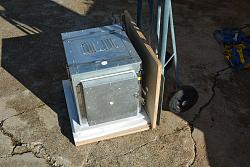
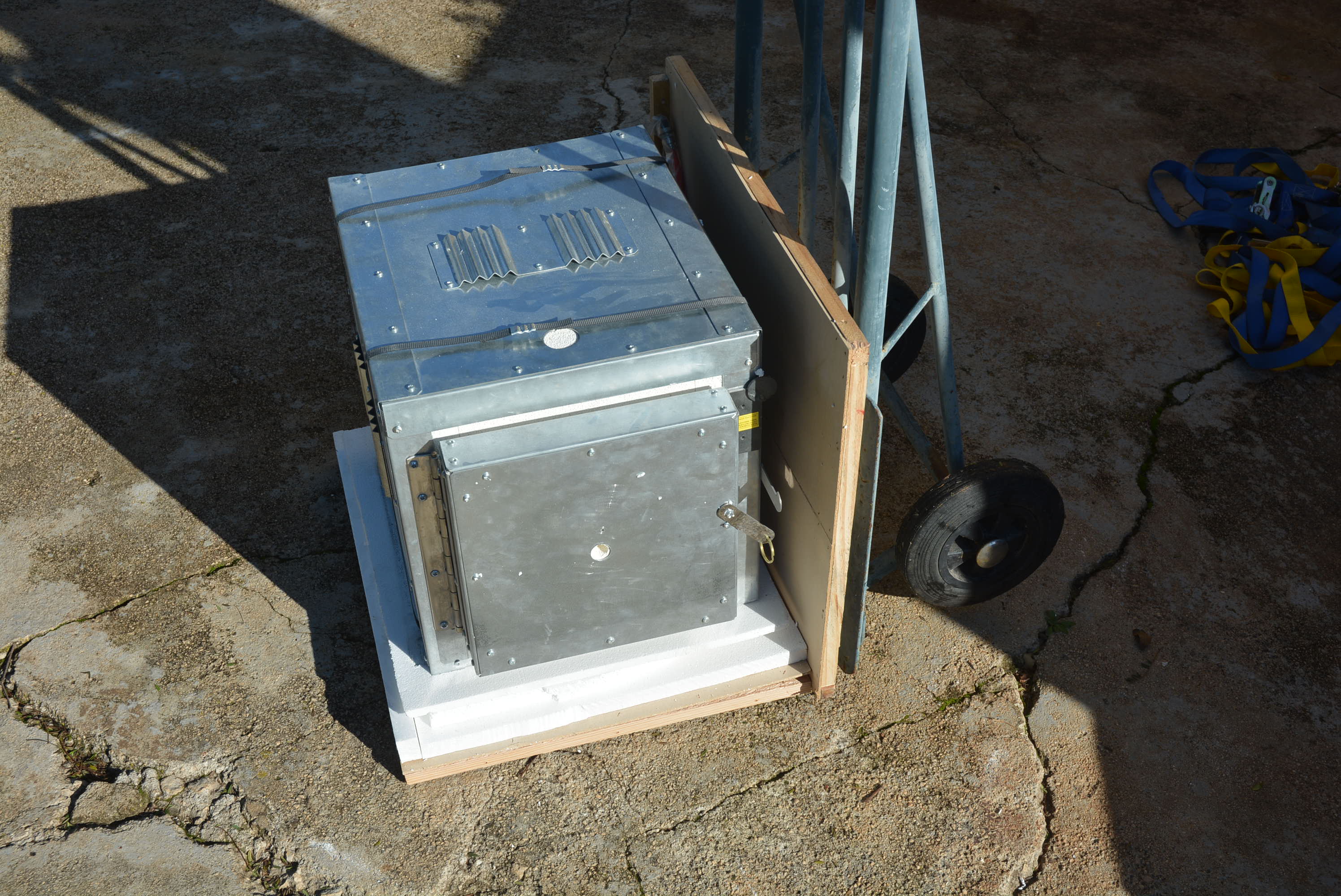
I was saved the trouble of making an oven as planned. Santa was kind enough to send me a bought one. 200 x 200 x 300mm.
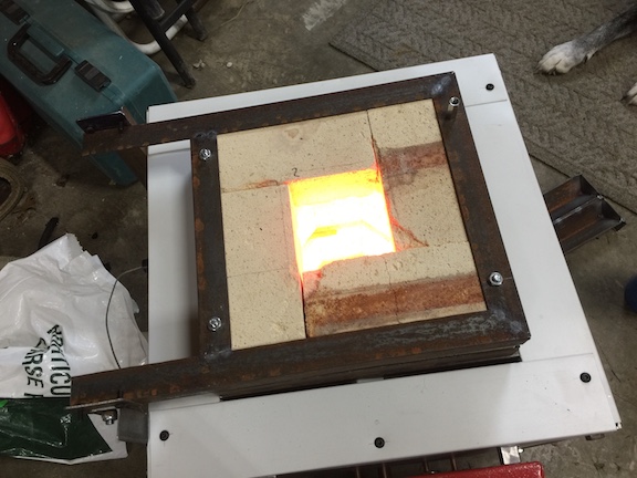
In initial testing I set the controller to 100 C and let it stabilise for 2 hours. I then put various thermocouples that I had in through the peep hole on the door and let them stabilise. I consistently got 112/113 degregardless of the depth of insertion. 12/13 deg difference to the control sensor at 100 C is unacceptable, especially for steel tempering.
Therefore I am thinking of adding a fan to even out the temperature. I am thinking about mounting a motor on the outside of the door with a shaft passing through the peep hole to a fan inside. Has anyone here had experience with forced circulation in benchtop size ovens?

 LinkBack URL
 About LinkBacks


 Reply With Quote


Bookmarks