Free 186 More Best Homemade Tools eBook:  
Get 2,000+ tool plans, full site access, and more.

User Tag List

Page 1 of 2 1 2 LastLast
Results 1 to 10 of 11

Thread: Heavy duty pipe/ring roller

  1. #1
    Supporting Member MeJasonT's Avatar
    Join Date
    Jun 2016
    Location
    Lake District in UK
    Posts
    432
    Thanks
    455
    Thanked 279 Times in 162 Posts

    MeJasonT's Tools

    Heavy duty pipe/ring roller

    Heavy duty pipe/ring roller-heavy-duty-pipe-roller.png

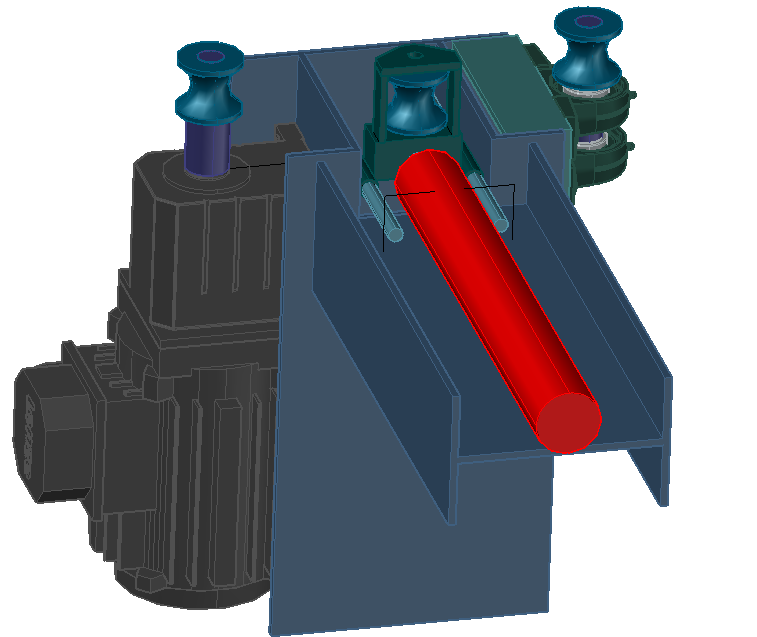
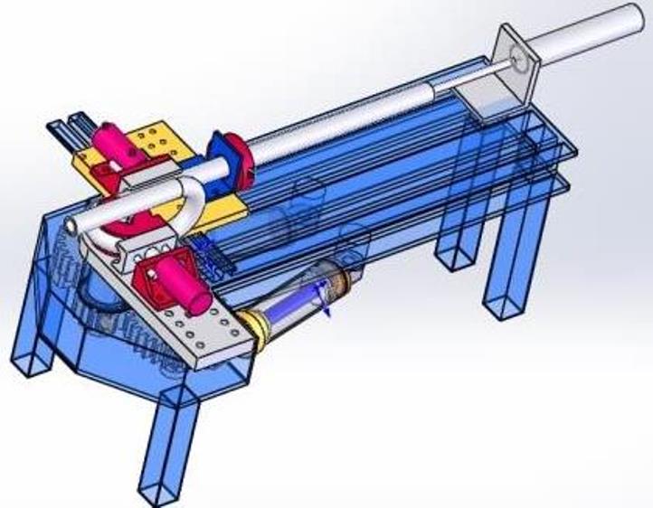
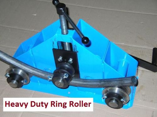
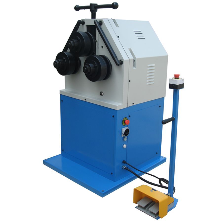
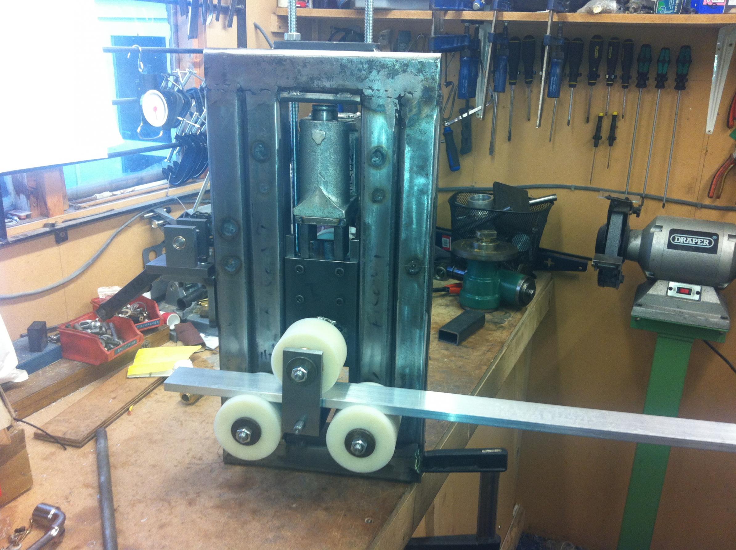
    I have started work work on a heavy duty ring roller to roll 2" scaffold pole, I have a crazy customer who wants a handrail made for a staircase and I don't have 4 grand lying around. I have attached the Autocad DWG file and pictures of my progress. Heavy Duty Ring Roller.dwg

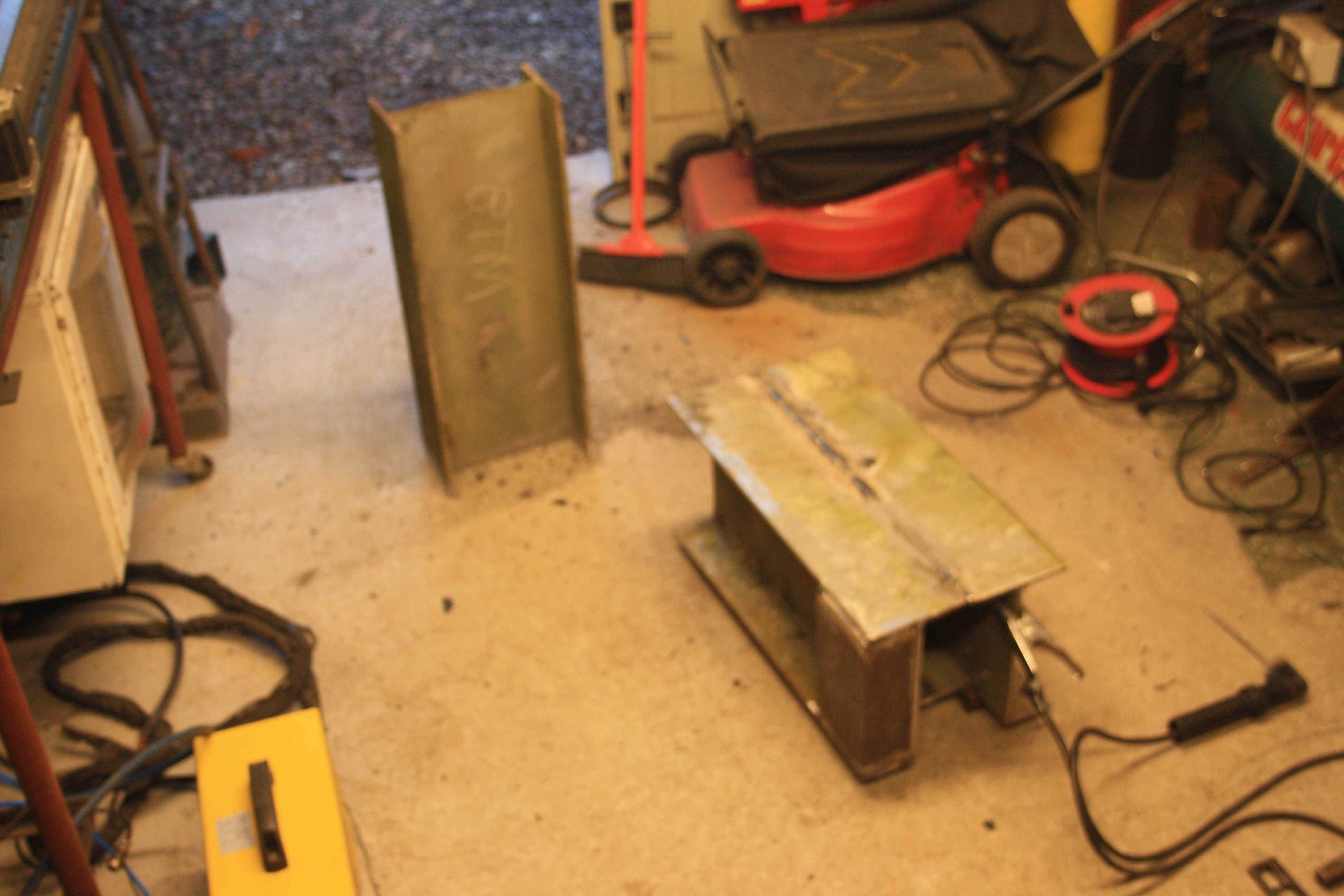
    I had all the parts lying around I needed to try building it

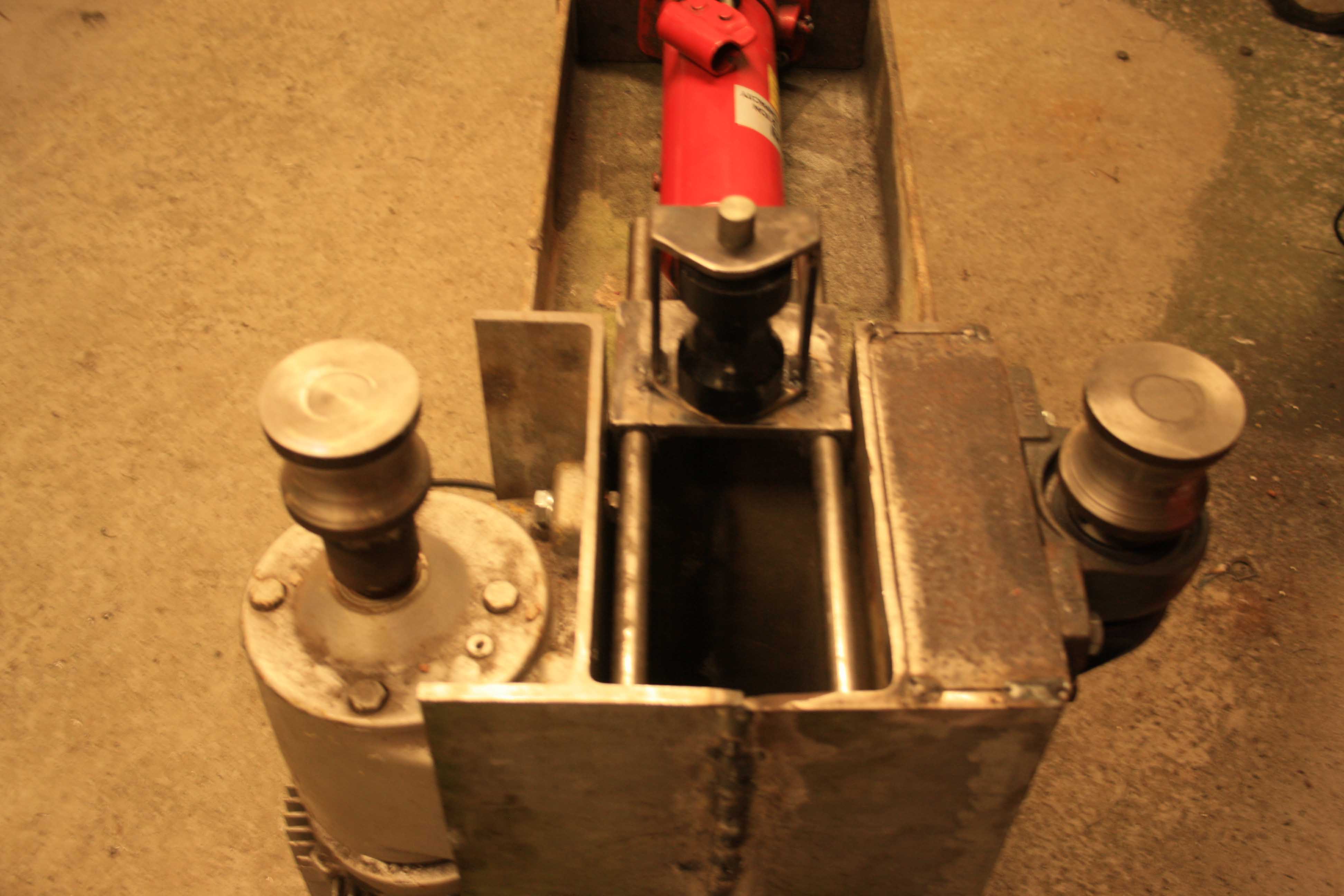
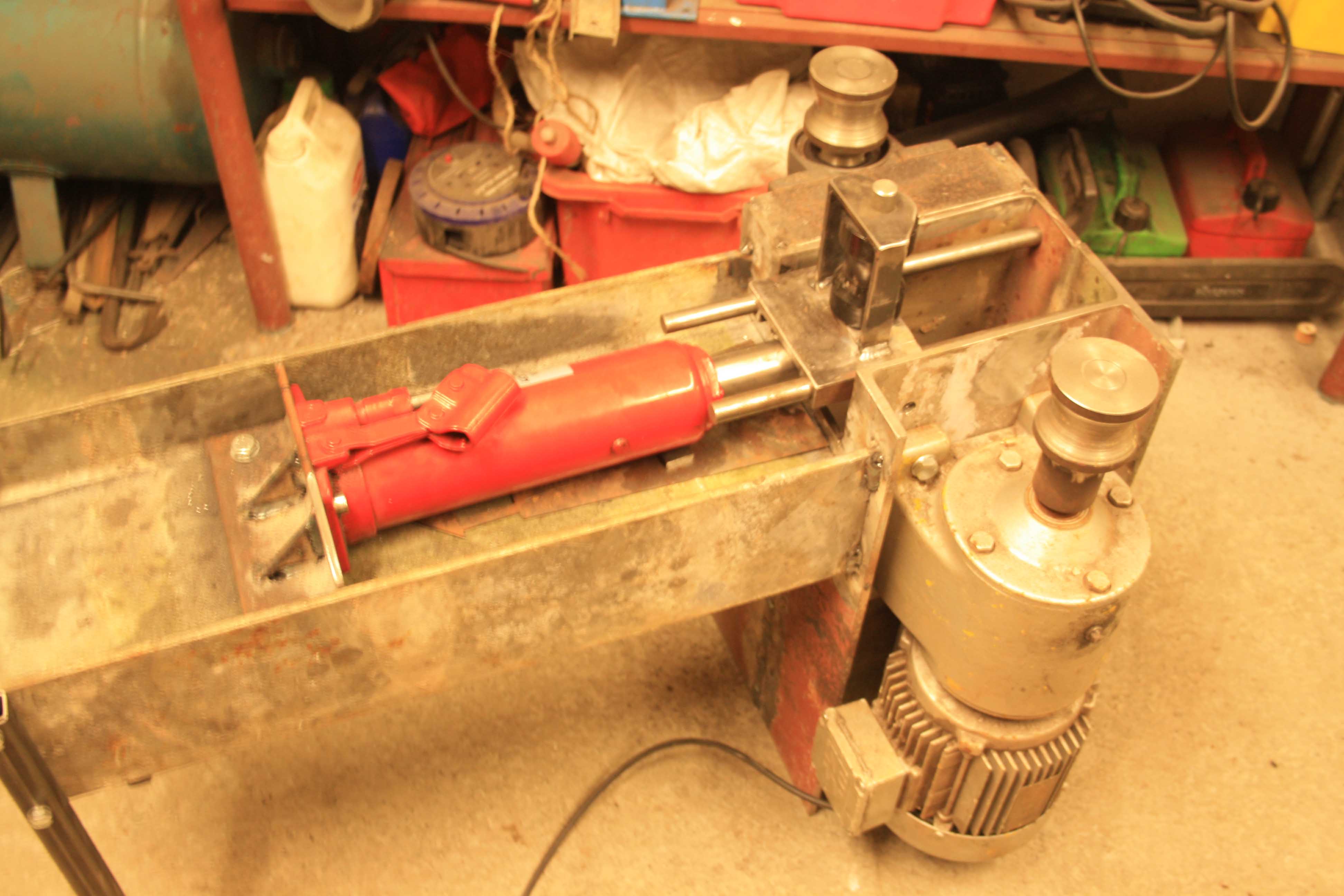
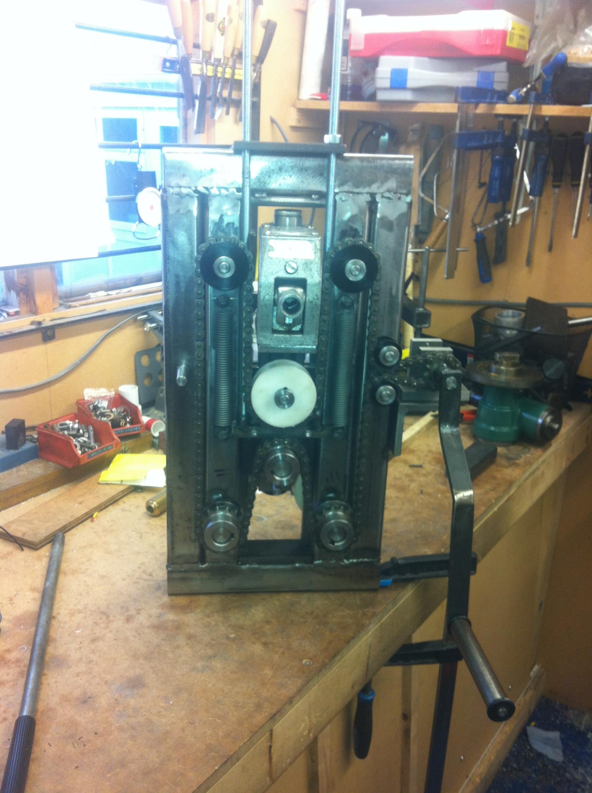
    The frame has been completed, rollers and feed slider, I will add more build information as I progress through the build.

    Heavy duty pipe/ring roller-img_0024a.jpg

    Heavy duty pipe/ring roller-img_0033a.jpg

    Heavy duty pipe/ring roller-img_0027a.jpg

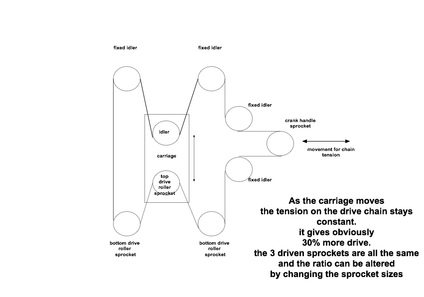
    I have a couple of bug bears, I cant fit a chain between the two drive rollers as the feed slide is in the way and the rollers are further apart than I would have liked. I cant get hold of cheap chain and sprockets - I was thinking 125cc motor cycle chain and 3 x front sprockets (idler and a sprocket for each drive roller).

    186 More Best Homemade Tools eBook
    Citizen of the "New democratic" Republic of Britain, liberated from the EuroNation

  2. The Following 3 Users Say Thank You to MeJasonT For This Useful Post:

    Jon (Jan 11, 2018), Seedtick (Jan 13, 2018), Tuomas (Jan 12, 2018)

  3. #2
    Supporting Member Frank S's Avatar
    Join Date
    Aug 2015
    Location
    Peacock TX
    Posts
    11,178
    Thanks
    1,974
    Thanked 8,766 Times in 4,195 Posts

    Frank S's Tools
    I might offer a little input if you would like. From the pictures you provided your drive rollers are not as much being too far apart as they are way too small in diameter
    The optimum major diameter of the drive and idler roller dies would be 4x the diameter of the pipe being rolled this would afford a better drive friction to pull or push the pipe. The depth of the radius grove would be half the OD of the pipe with the radius of the grove matching the radius of the pipe being formed. The ram for adjusting the bend radius should be on center-line with the idler die for maximum strength and reduction of the creation of a bending moment in the mounting structure the idler is mounted in.
    I am not at all confident the shaft in the gear reduction housings will be able to take the side loading stresses but I have no data on its size or specs it may be fine as long as you do not apply too much power to the ram on each pass. Good luck

    2000 Tool Plans
    Never try to tell me it can't be done
    When I have to paint I use KBS products

  4. The Following 2 Users Say Thank You to Frank S For This Useful Post:

    DIYer (Jan 12, 2018), Toolmaker51 (Jan 12, 2018)

  5. #3
    Supporting Member MeJasonT's Avatar
    Join Date
    Jun 2016
    Location
    Lake District in UK
    Posts
    432
    Thanks
    455
    Thanked 279 Times in 162 Posts

    MeJasonT's Tools
    Thanks Frank,
    I think I should have asked you guys for input first.
    I was working on the basis that the manual hand cranked one I purchased from some great guys in Poland works really well, granted on 30 mm tube.
    The cylinder is on the centre line and the rollers have been machined to 1/2 of the materials diameter (scaff pole). I didn't think about the 4 x OD for the rollers but it makes a lot of sense. I was thinking of wimping out when applying the force onto the pipe, I tend not to go for broke with tools anyways.
    I very much appreciate your offer of luck, I think i will need it.
    Citizen of the "New democratic" Republic of Britain, liberated from the EuroNation

  6. #4
    Supporting Member MeJasonT's Avatar
    Join Date
    Jun 2016
    Location
    Lake District in UK
    Posts
    432
    Thanks
    455
    Thanked 279 Times in 162 Posts

    MeJasonT's Tools
    Frank,
    At least you didn't spot that the cylinder is on its side and inst happy, i'm quite chuffed i got one thing passed scrutiny.
    oops did I say that out loud.
    J.
    Citizen of the "New democratic" Republic of Britain, liberated from the EuroNation

  7. #5
    Supporting Member Frank S's Avatar
    Join Date
    Aug 2015
    Location
    Peacock TX
    Posts
    11,178
    Thanks
    1,974
    Thanked 8,766 Times in 4,195 Posts

    Frank S's Tools
    J. I wasn't trying to be critical of your work or scrutinizing it to the point of picking it apart. Many jacks such as your are perfectly happy lying on their side but usually want the pump either rotated to the side or better yet tucked under them . As for being on center line I meant on center line of the bending radius of the part being formed. Having said that I have in the past designed and built pipe bending machines where the shafts the dies were mounted on had the bearings on 1 side only
    Here is a picture of a CAD assembly drawing of one of the machines I made. for concept of size the gears driving the dies were 100 MM thick the plates under the dies were 60 MM thick. The 15KW motor could bend annealed tubing up to 80 MM in diameter 10 MM wall thickness or 100 MM 5 MM thick, drawn over a ball mandrel.
    Heavy duty pipe/ring roller-hyd-pipe-bender4.jpg
    Last edited by Frank S; Jan 12, 2018 at 09:08 AM.
    Never try to tell me it can't be done
    When I have to paint I use KBS products

  8. #6
    Supporting Member MeJasonT's Avatar
    Join Date
    Jun 2016
    Location
    Lake District in UK
    Posts
    432
    Thanks
    455
    Thanked 279 Times in 162 Posts

    MeJasonT's Tools
    Hi Frank,

    I didn't take it as a criticism, more like a constructive observation. I'm really chuffed when I get a response from you as you are one of the members I respect and know you always offer good advice.
    The cylinder needed rotated 90 degrees in its horizontal position, it got pissed when i tried to pump it where it was, its reservoir must have been below the pump inlet. luckily it has been rectified.

    The roller i based this design on was an improvement on this roller which I already have

    Heavy duty pipe/ring roller-s-l500.jpg

    https://www.ebay.co.uk/itm/Heavy-Dut...oAAOxyOM5RZzEm
    ideally what I was after is one of these

    Heavy duty pipe/ring roller-s-l1600.jpg

    https://www.ebay.co.uk/itm/Power-Sec...oAAOSwVFlUJF-M

    The machine you have built/provided drawing for is a beast, thick wall pipe, i'm well impressed. I was thinking of additional ideas to incorporate into my heavy duty Roller.

    The cylinder is from a pipe bender i already have
    Heavy duty pipe/ring roller-s-l1600-1-.jpg

    I'm thinking if i add different dies and mechanisms to the roller i will be able to get it to be more like a metal worker, also plan to add dies to form scrolls as well.

    I have seen a few homebuilt pipe ring rollers on youtube and decided it wasn't too scary to try building one.

    Thanks again for your input
    J.
    Citizen of the "New democratic" Republic of Britain, liberated from the EuroNation

  9. #7
    Supporting Member Frank S's Avatar
    Join Date
    Aug 2015
    Location
    Peacock TX
    Posts
    11,178
    Thanks
    1,974
    Thanked 8,766 Times in 4,195 Posts

    Frank S's Tools
    The factory built one shown in the 2nd picture was manufactured by ACL out of Guangzhou China ACL stands for America China Limited. the reason I know this is I have toured their factory on more than one occasion a company I was with in the Middle East was the sole distributor for them in the M.E. for a number of years that machine is well suited for rolling small angle iron Channels and beams, as well as flat bars and solid rounds, with the correct dies it will do hollow section square rectangular and cylindrical tubing'sand sch 40 pipe up to about 1 1/2" for 2 inch pipe the rollers are too close together and do not allow for large enough diameter dies. they can be rolled on it but due to the size limitations the pipes become deformed but they have much larger models as well.
    in my factory I had several of their machines but built to my specifications for instance my 12mm x 2.5 meter plate roll had 300 mm diameter rollers instead of the standard 220 mm rollers the drive rolls were on 600 mm center to center spacing where as the std was 500 mm the top roll was powered up and down with 400 mm of vertical travel with selectable independent down force for making tapered roll forming I also had a 250 ton 12 mm by 3 meter press break NC controlled with powered back gauge and matching shear to round off our cadre of their machines was our 150 ton mulit station iron worker
    So yes I am quite familiar with the little roll you showed. I have one of those small hydraulic pipe benders you showed in the last pic. again my issue with it is the 2 guide rollers being so small in diameter they cause the pipes to be deformed I keep threatening to machine a set of 3 to 6 inch long guide shoes to use in lew of the rollers but have not done it yet.
    In your first picture to me that one looks to be more substantial than the current one you are building but without laying them side by side it would be hard to tell for sure. It just looks like all it would need would be power and larger diameter dies. But hey that is why we build and build again and again until we are satisfied. In my case it seems I and never completely content after a build.
    Never try to tell me it can't be done
    When I have to paint I use KBS products

  10. #8

    Join Date
    Aug 2015
    Location
    UK, midlands
    Posts
    5
    Thanks
    1
    Thanked 2 Times in 1 Post

    Fire blade's Tools
    Hello J. Here's one I made to roll some wheel rims out. All 3 rolls are driven by 1/2" x 5/16" roller chain using a paternoster system. you could make it any size you like.
    The wheels were from 2" aluminium channel but I've rolled a 4" rad from 5/8" x 1" aluminium on it. you can adjust the wind crank ratio by altering the gearing. I initially used an old bottle jack but the pressure dropped during the roll giving me ovals so I used some 20mm allthread.

    Just something else to think about.

    Best regards MickHeavy duty pipe/ring roller-img_1052.jpgHeavy duty pipe/ring roller-img_1050.jpg

  11. The Following 2 Users Say Thank You to Fire blade For This Useful Post:

    MeJasonT (Dec 3, 2018), Tuomas (Jan 19, 2018)

  12. #9
    Content Editor
    Supporting Member
    DIYer's Avatar
    Join Date
    Aug 2013
    Posts
    3,056
    Thanks
    772
    Thanked 1,850 Times in 1,652 Posts


    Thanks Fire blade! We've added your Rim Roller to our Ring Rollers category,
    as well as to your builder page: Fire blade's Homemade Tools. Your receipt:


  13. #10
    Supporting Member MeJasonT's Avatar
    Join Date
    Jun 2016
    Location
    Lake District in UK
    Posts
    432
    Thanks
    455
    Thanked 279 Times in 162 Posts

    MeJasonT's Tools
    Hi Mick, thanks for the input.
    I was wondering how the cylinder might behave, when it was used in the old pipe bender it didn't seem to drop pressure but I guess i didn't pay much attention to it on the bender. Its kind of a go for broke type of mechanism when used on the bender.

    I'm interested to see some pictures of your chain setup if you don't mind posing some.

    I completed the design/build that I intended to build last night, it has not received any further mods yet as suggested by friends on our great homemade tool network. mainly Frank and yourself.

    I'm rewiring the motor this morning as the cable was too short and then its time for the big test. Two scary things lie before me, posting a video on here if it works as i'm not much of a selfie type person and finding out it just cavitate's and does not actually drive the bar through. I will also have to get the inverter handbook out and set up dc braking as it is currently ramping down when it stops, I could end up with a metre of pipe through before it stops and I can change direction.

    I'm confident it will work as there is not very much to impress me about the manual one pictured earlier in the post, not much technology to it.

    Ill post back later with the results.
    cheers Jason
    Last edited by MeJasonT; Jan 19, 2018 at 03:36 AM.
    Citizen of the "New democratic" Republic of Britain, liberated from the EuroNation

Thread Information

Users Browsing this Thread

There are currently 1 users browsing this thread. (0 members and 1 guests)

Bookmarks

Posting Permissions

  • You may not post new threads
  • You may not post replies
  • You may not post attachments
  • You may not edit your posts
  •