Free 186 More Best Homemade Tools eBook:  
Get 2,000+ tool plans, full site access, and more.

User Tag List

Page 1 of 2 1 2 LastLast
Results 1 to 10 of 15

Thread: Help Advice Construction Swivel Arm Jib Crane Hoist

  1. #1
    Supporting Member forgiaro's Avatar
    Join Date
    Apr 2014
    Location
    italia
    Posts
    27
    Thanks
    0
    Thanked 11 Times in 8 Posts

    forgiaro's Tools

    Help Advice Construction Swivel Arm Jib Crane Hoist

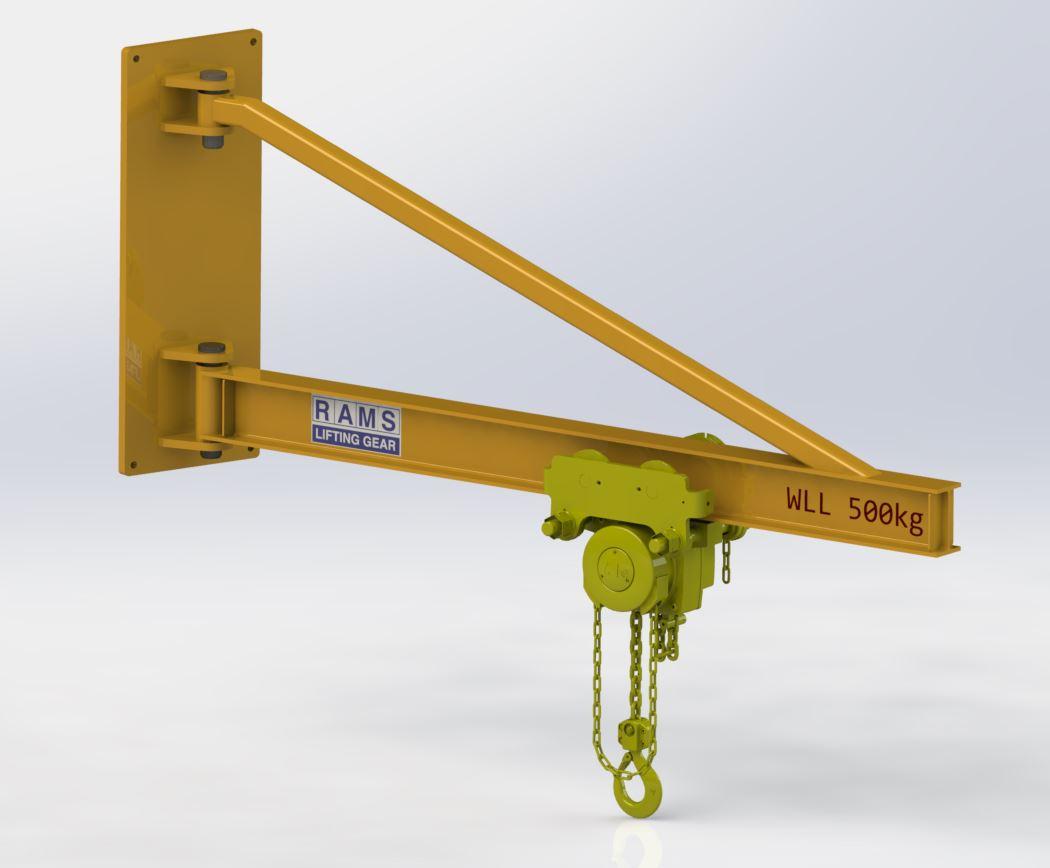
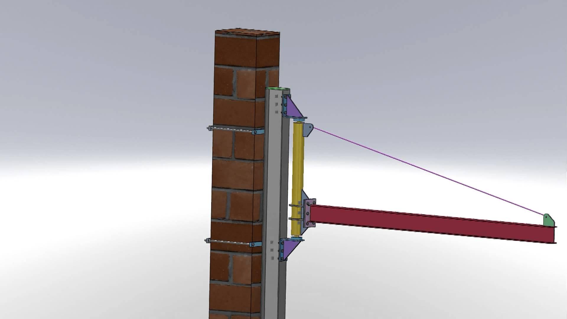
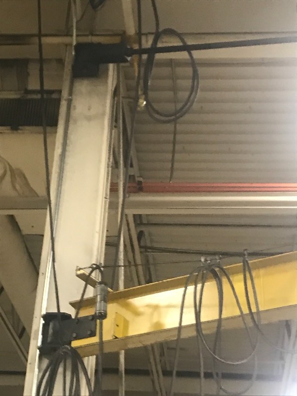
    Help Advice Construction Swivel Arm Jib Crane Hoist:
    hi, I should make a swivel arm for a small jib crane to be installed in my small lab. size description
    ten feet height under hook, ten feet arm length jib crane

    one thousand four hundred pounds, to be juxtaposed and bolted to reinforced concrete pillar in my laboratory. I would like to build it all in iron beams, what do you recommend? How to build hinge for arm rotation? thanks to those who want to help me and provide advice and useful tipsHelp Advice Construction Swivel Arm Jib Crane Hoist-bandiera-3.jpgHelp Advice Construction Swivel Arm Jib Crane Hoist-gru.jpg


    Help Advice Construction Swivel Arm Jib Crane Hoist-6005044.jpg

    186 More Best Homemade Tools eBook
    Che tu creda di farcela o di non farcela avrai comunque ragione

  2. The Following User Says Thank You to forgiaro For This Useful Post:

    Seedtick (May 1, 2018)

  3. #2

    Join Date
    Sep 2017
    Posts
    6
    Thanks
    0
    Thanked 1 Time in 1 Post
    need more pictures.

    2000 Tool Plans

  4. #3
    Supporting Member metric_taper's Avatar
    Join Date
    Mar 2017
    Location
    Marion, Iowa
    Posts
    585
    Thanks
    228
    Thanked 257 Times in 153 Posts

    metric_taper's Tools
    To attach this to a concrete column, that is only intended for compression loads, would result in failure. Concrete is very good in compression, but this sort of load would induce a moment force, where the concrete would be in tension in 2 places. The 10' length with a 1400 lbs load is one heck of a moment.
    You do not want to attach this to your concrete support column.
    The safe solution is a separate installed column designed to support this large moment arm. And this column could be a large diameter pipe, buried in the ground with concrete to keep it from displacing earth.
    I'm on a new computer and don't have my structural program loaded. And installing it seems to have a missing .dll file issue. The moment will be increased once the known weight of the steel is added. That is the steel used to hold the 1400 lbs load up, has to be added into the calculation.
    How much deflection can you live with, too much and a rolling trolley moves to the end of the beam.
    Last edited by metric_taper; May 1, 2018 at 08:00 PM.

  5. The Following 4 Users Say Thank You to metric_taper For This Useful Post:

    NortonDommi (May 4, 2018), Paul Jones (May 3, 2018), PJs (May 2, 2018), Sleykin (May 2, 2018)

  6. #4
    Supporting Member forgiaro's Avatar
    Join Date
    Apr 2014
    Location
    italia
    Posts
    27
    Thanks
    0
    Thanked 11 Times in 8 Posts

    forgiaro's Tools
    Help Advice Construction Swivel Arm Jib Crane Hoist-img_4900.jpg

    Help Advice Construction Swivel Arm Jib Crane Hoist-bracci10.jpg
    Help Advice Construction Swivel Arm Jib Crane Hoist-gru_114.jpg
    Help Advice Construction Swivel Arm Jib Crane Hoist-gru_214.jpg

    Help Advice Construction Swivel Arm Jib Crane Hoist-gru_511.jpg


    Help Advice Construction Swivel Arm Jib Crane Hoist-gru_610.jpg


    Help Advice Construction Swivel Arm Jib Crane Hoist-gru_710.jpg

    Help Advice Construction Swivel Arm Jib Crane Hoist-gru.jpg
    on the net I found these handcrafted photos, clearly not bolted the rotating boom directly to the reinforced concrete pillar but I will put a column in H-shaped steel beam to it, what do you think? would you have photos or drawings? clearly not heavy loads maximum two hundred kilograms, I realize that it is a cantilevered shelf very urgent and that I have to counter it with the diagonal type tie rods, other ideas and suggestions? thanks again for your precious time and valuable advice
    Che tu creda di farcela o di non farcela avrai comunque ragione

  7. #5
    Supporting Member metric_taper's Avatar
    Join Date
    Mar 2017
    Location
    Marion, Iowa
    Posts
    585
    Thanks
    228
    Thanked 257 Times in 153 Posts

    metric_taper's Tools
    Some of the photos you've found are safe, some unknown, but the "artist drawing" showing brick masonry is totally misleading.
    I'm guessing your looking to lift 600Kg, on a 3 meters jib crane. This has to be engineered with real details of the building if you expecting the building to play any roll in the static and dynamic forces to support this.
    Here in the states we have a China tool importer call Harbor Freight (Horrible Fright ). They sell a portable rolling gantry crane that is good to 1 ton (2000lbs~900Kg).

    Note this can be raised and lowered with a cable and telescoping construction (not while loaded). The distance between the support posts is ~2.4meter.
    If your floor is smooth and can support this, I would suggest finding your Italian counter part for this importer. The current price here is $730 plus tax.

  8. The Following User Says Thank You to metric_taper For This Useful Post:

    Paul Jones (May 3, 2018)

  9. #6
    Supporting Member forgiaro's Avatar
    Join Date
    Apr 2014
    Location
    italia
    Posts
    27
    Thanks
    0
    Thanked 11 Times in 8 Posts

    forgiaro's Tools
    Help Advice Construction Swivel Arm Jib Crane Hoist-pilastro.jpg
    the reinforced concrete pillar is about 5 meters high with a square cross section 50 x 50 cm, I would like to realize the structure in H beams what do you recommend? I have to build the hinge for the rotation of the arm to the pole, which will be anchored by threaded dowels to the foundation beam and bolted to the reinforced concrete column by means of brackets and 20 mm section threaded bars
    tables beams to h

    HEM beams, European standard wide flange H beams dimensions, specifications. HE M beams in accordance with former standard Euronorm 53-62
    http://www.twc.co.th/PDF.H_beam.pdf


    IPE beams. European standard universal I beams (I section) with parallel flanges. Dimensions, specifications, accordance with former standard EU 19-57

    Help Advice Construction Swivel Arm Jib Crane Hoist-jib-crane.jpg
    Che tu creda di farcela o di non farcela avrai comunque ragione

  10. #7
    PJs
    PJs is offline
    Supporting Member PJs's Avatar
    Join Date
    Sep 2014
    Location
    Northern CA
    Posts
    1,841
    Thanks
    8,337
    Thanked 1,118 Times in 718 Posts

    PJs's Tools
    I agree with Metric_Taper's first statements regarding the engineering but it must also be added that this is a Swivel Cantilever which adds more credence to how the (Post/Wall) building was designed. If you add the weight of your gib system (including hoist/winch) to the 1400 pound max load, the wall/post Must be able to sustain at least 1.5X (to be safe) in all directions of the swing. Additionally, any swinging/oscillations of the 1400lb load at different heights up to 10' in addition to the swivel will cause some pretty high torsional stresses to the post/wall and the gib/hinge and must be added to the calcs.

    You can purchase prefabricated, load rated, swivel Jibs but you must insure that your mount will support all the above, and I would add .5X just for good measure. If you are going to build this from scratch, there are some beam calculators on line or you can reference the Marks Manual or other Structural books to insure you stay safe and the building remains standing!

    PJ
    ‘‘Always do right. This will gratify some people and astonish the rest.’’
    Mark Twain

  11. The Following User Says Thank You to PJs For This Useful Post:

    Paul Jones (May 3, 2018)

  12. #8
    PJs
    PJs is offline
    Supporting Member PJs's Avatar
    Join Date
    Sep 2014
    Location
    Northern CA
    Posts
    1,841
    Thanks
    8,337
    Thanked 1,118 Times in 718 Posts

    PJs's Tools
    the reinforced concrete pillar is about 5 meters high with a square cross section 50 x 50 cm, I would like to realize the structure in H beams what do you recommend? I have to build the hinge for the rotation of the arm to the pole, which will be anchored by threaded dowels to the foundation beam and bolted to the reinforced concrete column by means of brackets and 20 mm section threaded bars
    tables beams to h
    The pillar construction is most important i.e., rebar size & amount, type of concrete, the depth of anchor into the foundation/ground and what it is supporting above. In your second picture and description it looks that you will be using H beam for the vertical support. Additionally you must keep in mind that your pillar loading is at ~2/3 of the height of the pillar...a different set of calcs are needed for that position on the pillar. Personally I would use heavy wall SQ tube because of the swivel loading and oscillation issues. It should also be anchored or inserted (Footing-some depth?) into the floor and possibly the ceiling and might be wide steel plate strapped to the pillar...any drilling into the pillar will compromise its integrity.

    The saw tooth design of your support looks to be adequate but keep in mind the torsional issues for choosing the type of material (shape) for building it. Also keep in mind the size of the pins for the swivel hinges to support all that weight.

    Build it like your life or someone you love depends on it.

    PJ
    Last edited by PJs; May 2, 2018 at 04:59 PM.
    ‘‘Always do right. This will gratify some people and astonish the rest.’’
    Mark Twain

  13. #9
    Supporting Member metric_taper's Avatar
    Join Date
    Mar 2017
    Location
    Marion, Iowa
    Posts
    585
    Thanks
    228
    Thanked 257 Times in 153 Posts

    metric_taper's Tools
    Your getting close to 4 meters with a 500Kg load. You need to hire a license engineer. It will probably cost you 4-8 days of your salary. Even if the masonry column is .5m sq. I don't see a safe way to transfer the forces without having extreme detail about the column, and what it is holding up.
    I tried to push you in a safe direction.
    Many years ago I went down this same path of a jib crane, and adding it to a building after the fact, is just too much effort to properly support it. The other (safe) alternative is a bridge crane that is fixed and uses added steel support columns. That is what I ended up building. I used very light steel wide flange beams that were 6" tall, by 6.8lbs/foot (may be 7.2lbs/ft). This made 8 foot sections liftable by ME on a ladder. I used 2x4 steel tubing 1/4" wall thickness for the support columns. The columns have a welded plate on the each end, one to bolt to the floor, the other to bolt to the bridge sections. I have a 9/16" piece of round stock welded to the top of the bridge for a rail guide.
    Help Advice Construction Swivel Arm Jib Crane Hoist-img_20180502_120541.jpg

  14. #10
    Supporting Member forgiaro's Avatar
    Join Date
    Apr 2014
    Location
    italia
    Posts
    27
    Thanks
    0
    Thanked 11 Times in 8 Posts

    forgiaro's Tools
    bridge cranes I can not use for reasons of logistical space (the floor is old and yielding), the pillar is in reinforced concrete not masonry brick walls, I realize that the pillar is stressed by the effort of the lever of the braziio to strain of cutting, I realize that the unloading arm weighs about forty kilograms taking into account both the beam that the carriage that the chain hoist, I realize that when the cart will work to tip the beam much stresses the pillar. I formally put 500 kg as a load, but I do not think that ever so heavy a load, maximum 200kg I estimated, I would need a sturdy hoist for building I think. however the pins I found a bolt of 25 mm for the hinge of the beam and a 20 mm bolt for the support of the diagonal tie rod. for the pillar of the structure consulting the tables I believe that a H beam from 100mm to 3.90 meters in height is adefuata, the crosspiece for the arm I empirically chosen a ipe 120 mm x 3.50 meters, what do you think I'm inside how do you calculate? I used tapered bearings as a support for the revolving arm, what do you think? I have not yet bought the beams necessary for the realization, I wait for tips and suggestions thanks again for your precious time


    Tabella Profilati metallici - Travi HEA
    Tabella Carico utile - Travi IPE sollecitate a flessione
    Tabelle
    Tabella Profilati metallici - Travi IPE
    Calcolo trave appoggiata con carico concentrato
    Calcolo trave appoggiata con carico uniformemente distribuito
    https://www.fratellipelandi.it/pdf/travi.pdf
    Che tu creda di farcela o di non farcela avrai comunque ragione

Thread Information

Users Browsing this Thread

There are currently 1 users browsing this thread. (0 members and 1 guests)

Bookmarks

Posting Permissions

  • You may not post new threads
  • You may not post replies
  • You may not post attachments
  • You may not edit your posts
  •