 LinkBack URL
 About LinkBacks
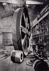
Are those big gears machined with the chevron shaped teeth? or is that two big gears put together to make one. Very impressive either way, I just have trouble imaging how they would machine the chevron.


Are those big gears machined with the chevron shaped teeth? or is that two big gears put together to make one. Very impressive either way, I just have trouble imaging how they would machine the chevron.


Machined as one gear...

Ah, I see they are created in several different ways.... as explained on https://en.wikipedia.org/wiki/Herringbone_gear
"A disadvantage of the herringbone gear is that it cannot be cut by simple gear hobbing machines, as the cutter would run into the other half of the gear. Solutions to this have included assembling small gears by stacking two helical gears together, cutting the gears with a central groove to provide clearance, and (particularly in the early days) by casting the gears to an accurate pattern and without further machining. With the older method of fabrication, herringbone gears had a central channel separating the two oppositely-angled courses of teeth. This was necessary to permit the shaving tool to run out of the groove. The development of the Sykes gear shaper made it possible to have continuous teeth with no central gap. Sunderland, also in England, also produced a herringbone cutting machine. The Sykes uses cylindrical guides and round cutters; the Sunderland uses straight guides and rack-type cutters. The W. E. Sykes Co. dissolved in 1983–1984. Since then it has been common practice to obtain an older machine and rebuild it if necessary to create this unique type of gear. Recently, the Bourn and Koch company has developed a CNC-controlled derivation of the W. E. Sykes design called the HDS1600-300. This machine, like the Sykes gear shaper, has the ability to generate a true apex without the need for a clearance groove cut around the gear. This allows the gears to be used in positive displacement pumping applications, as well as power transmission. Helical gears with low weight, accuracy and strength may be 3D printed."
Toolmaker51 (May 16, 2021)
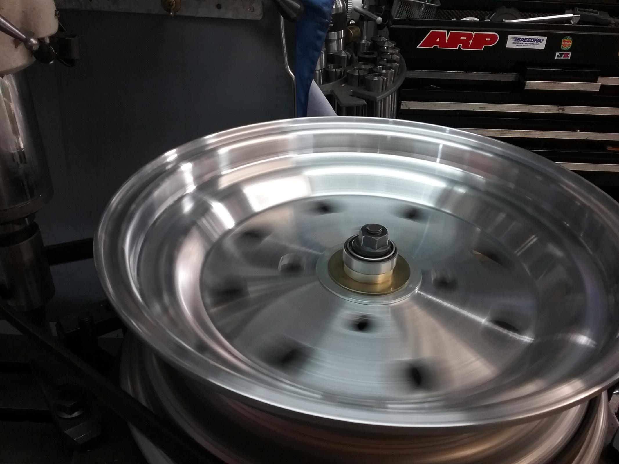
looks like there making the wheels for my racecar!!!! well...I had some that were forged and some that were spun. and some that were ****....I had some CMS wheels on the front of one of my cars...I thought that stood for China Made ****...I was informed those were made in cali.....fornia. I bought them new as I have all my wheels, they were the worst **** Ive ever seen, wobbly as hell, like 2-3mm run out side to side and the bolt pattern wasent even in the center that was off around 2 mm...how the **** can you make **** like that and charge for it???? I put them on my mill squared them up, straightened,recentered the bolt pattern, and added some lightening holes.. they were oh so much better when I finished.


Double helical cut tooth mill pinions. Mesta Machine Company.
Fullsize image: https://s3-us-west-1.amazonaws.com/h...s_fullsize.jpg

HomemadeTools.net founder (2012) and CEO
Join thousands of us, and start building your own tools today.
marksbug (May 24, 2021), nova_robotics (May 29, 2021)

Mesta built huge presses and stuff which would use gears and other parts this large.
I get so many questions when I see this BIG old photos;
Where is the rest of that machine, What did they do with it, How BIG was the machine that cut those gears, There must be some serious structure under that wood floor!! Maybe it is just wood laid over concrete to limit damage if something is dropped. etc
Interesting markings on the various bearing sections. I always mark things in similar fashion just incase it is possible to put them back together incorrectly. Those marks appear to be for some other purpose.
I saw some types of these under the Leonardo D. engerneering(I think, something like that,motion.somethen ) mustseeum in milan years ago,so awesome. great way to control back lash and thrust at the same time and adjustable too. I saw oh somuch in that dirt floor machine shop with 4 story mustseeum built over it. I even learned how DOM is made there....I had no idea, and no idea that stuff was going on centurys ago.I need to go back for another look for a few years.
Herringbone gears,,,i worked in a machine shop in 1998-2002 here in OKC , that had 1934 sydney lathe 20 " swing by 6 ft long bed,all the headstock gears were herringbone,6 speeds, u changed speeds by turning a two handed lever when the spindle was barely rotating,,fastest speed was 300,great lathe that could take a 1/4 inch cut all day ,,till a headstock bearing needed replacing or tightening up, which happened about every 6 months..

Yes Good Question,What were they Used for? Where are the Top Caps? Certainly Don't Put Your Fingers Anywhere Near Those Gears When Turning!
There are currently 4 users browsing this thread. (0 members and 4 guests)
 Posting Permissions

 Reply With Quote
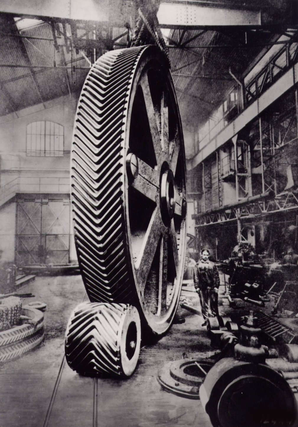


Bookmarks