-
6 Attachment(s)
Hydraulic press
First post here and its been a while since ive been on a forum. I have been working on this project for the last few months and I thought it was something worth sharing.
My first trade was as a diesel mechanic and because of that I have always appreciated having access to a large hydraulic press. Due to a change in occupation I no longer have the privilege. So I decided to source some components and make my own.
Most of the steel it 2nd hand and was destined for the scrap bin, as were the main hydraulic components.
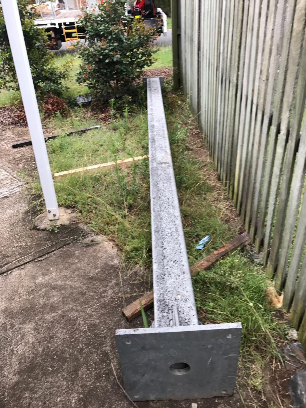
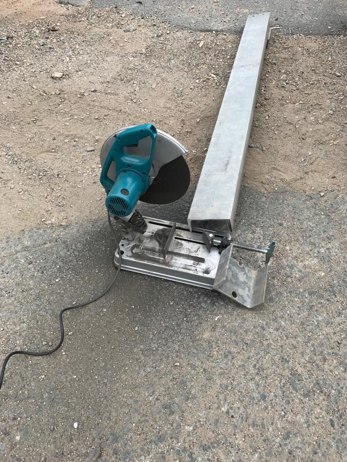
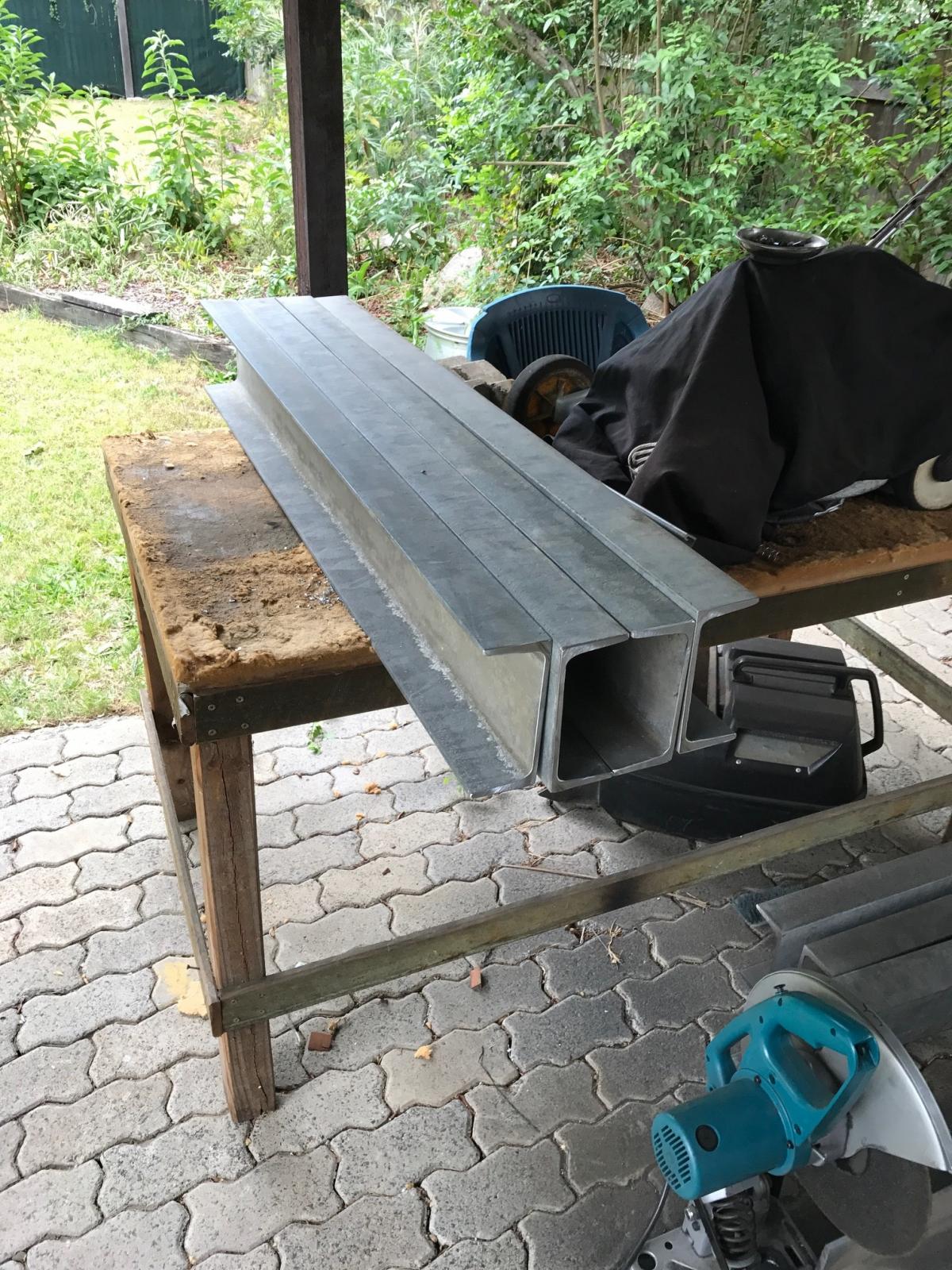
The main frame started with a 4m length of 200 x 200 x 6mm box section and a few lengths of 180 x 75mm tapered flange C channel. I decided on the dimensions, busted out the cut off saw and welder and started making a mess.
Attachment 27629
Attachment 27630
Attachment 27631
Attachment 27633
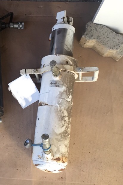
Fortunately before I had too much time invested in the steel frame I found the hydraulic cylinder and decided that the box section and channel were going to be too small for the capacity of the ram. So I put the press on hold and searched for some more steel.
Attachment 27632
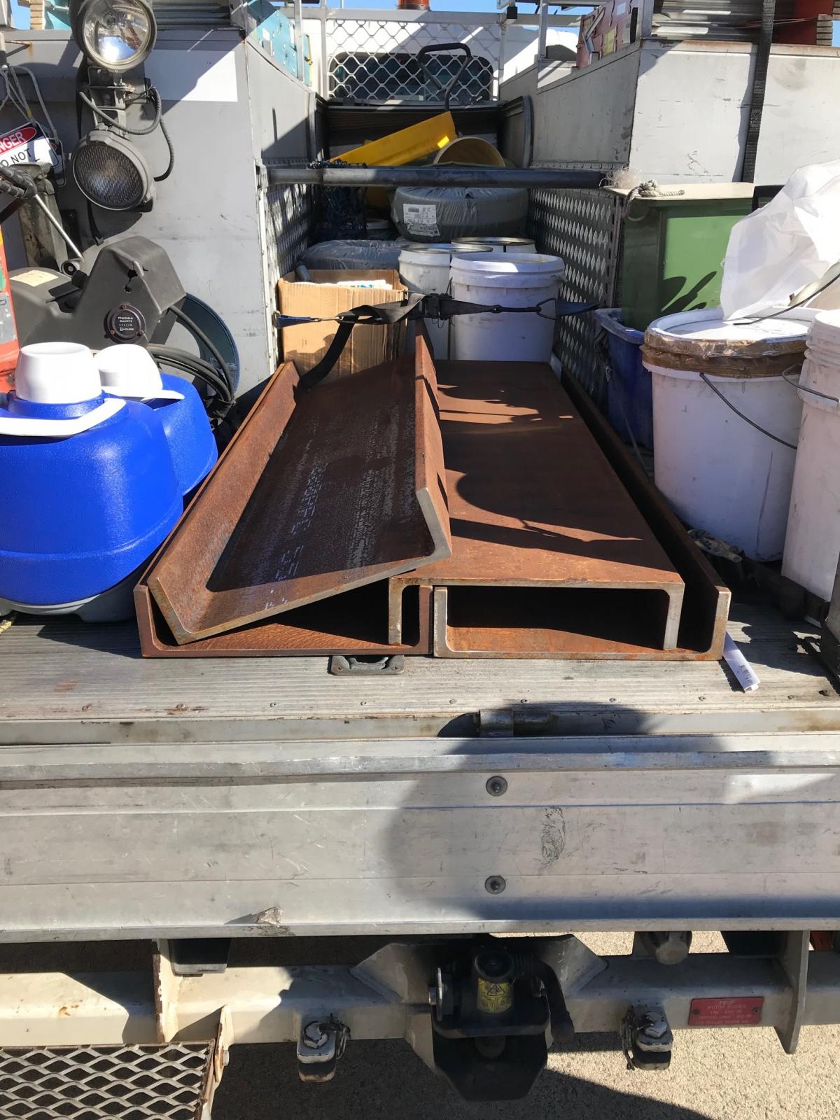
I walked into a local heavy fabrication shop that was having a clean up and asked about the 380mm x 100mm parallel flange channel they had sitting on the ground out the front. We agreed on a price and they cut me some to size.
Attachment 27634
Next step was to find some stronger uprights as I wasnt comfortable with the 6mm wall thickness.
-
5 Attachment(s)
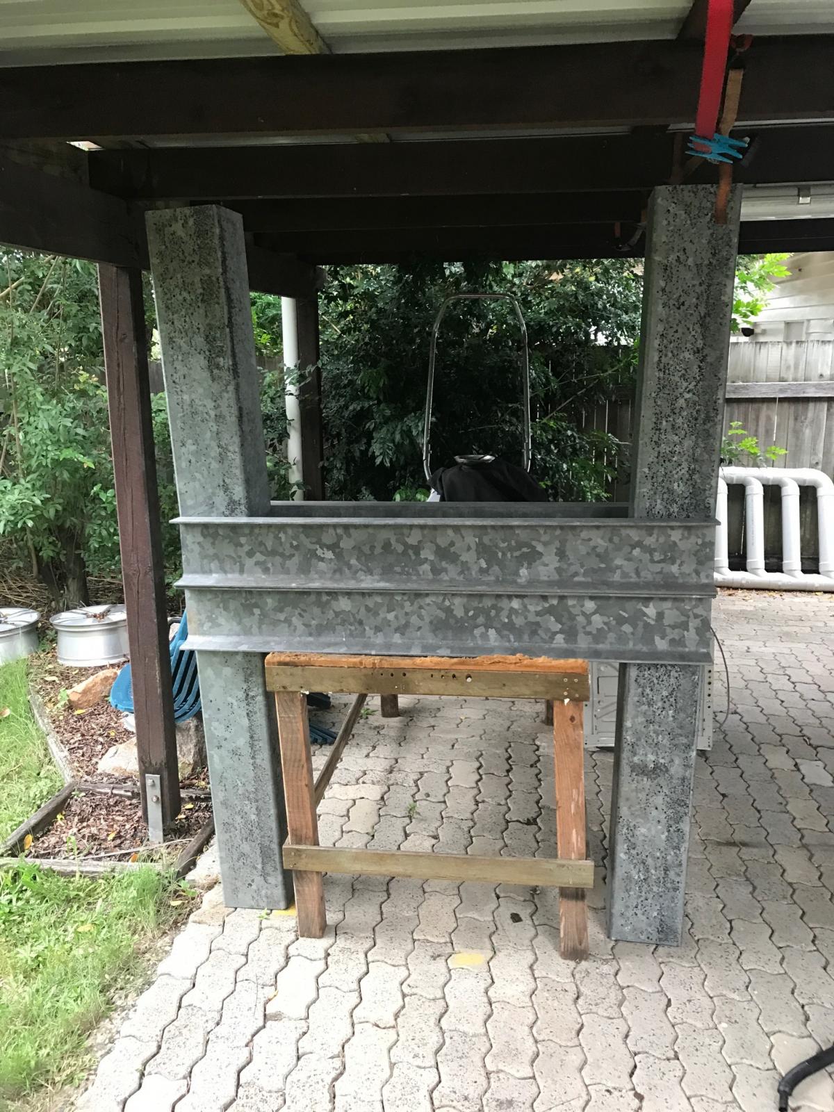
I couldn't find any suitable box, channel or I beam to make the uprights out of. So I settled on the 200mm x 200mm box I already had and decided to reinforce it instead. I did this by slipping two lengths of 180mm x 75mm taper flange channel inside each upright. this increased the wall thickness to 14mm.
Attachment 27635
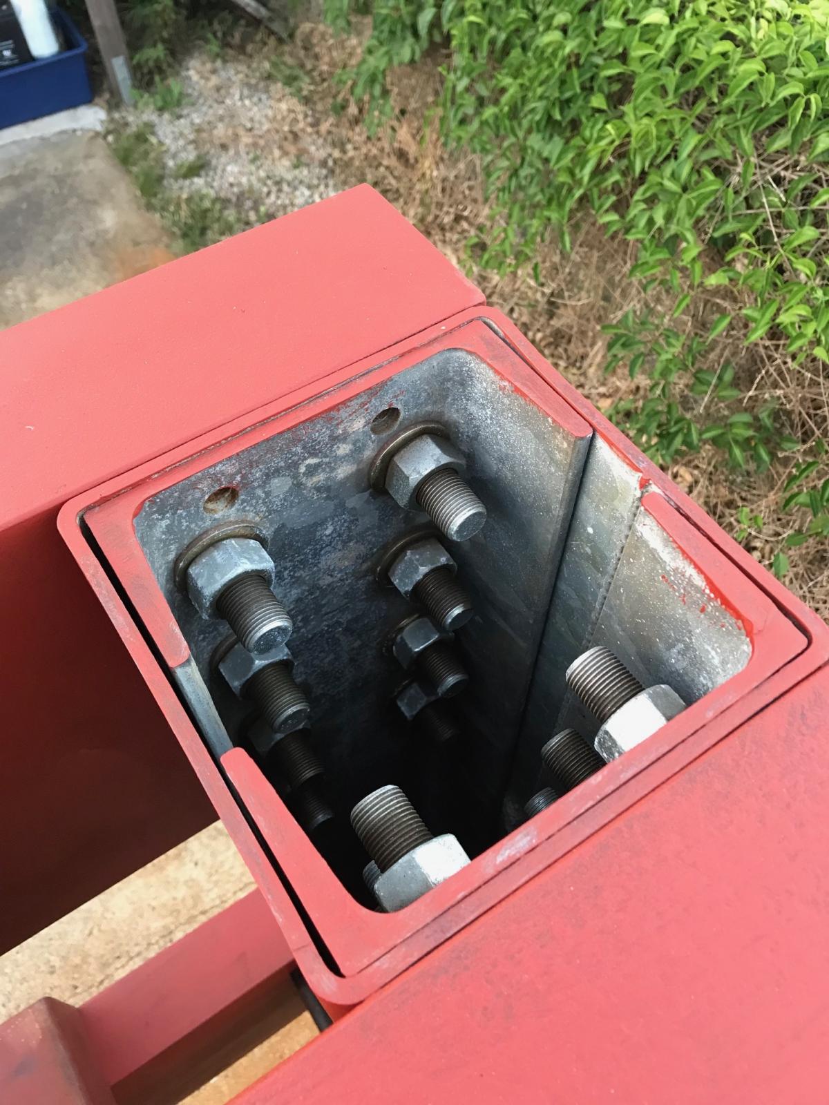
Next step was to bolt on the horizontal channel. I decided on 8 7/8th UNF bolts at each end of the channel. I used imperial bolts because they were cheaper and I had a 22mm annular cutter for my mag drill. The frame was squared up, measured diagonally to confirm, one bolt hole was drilled and a bolt installed before checking it was square again. then I drilled the remainder of the holes, installing the bolts as I went.
Attachment 27636
Attachment 27637
The press was flipped and the process started again, ensuring everything was still perfectly square.
Attachment 27638
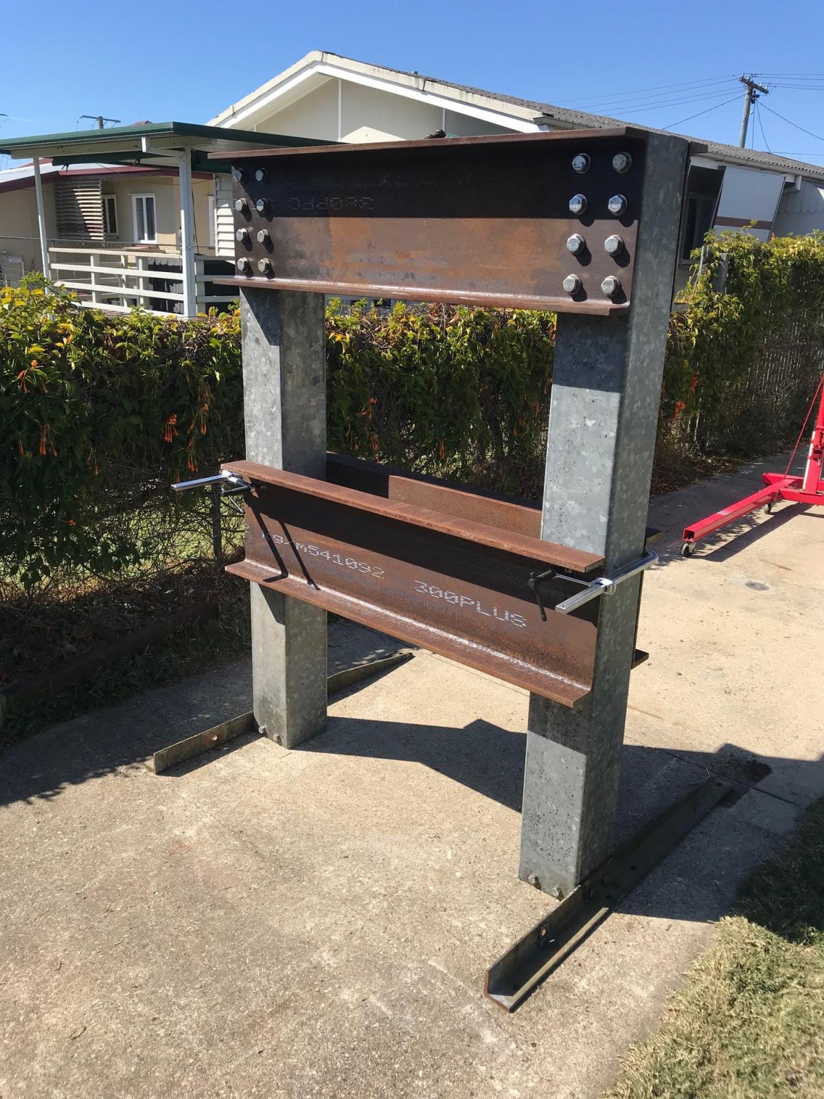
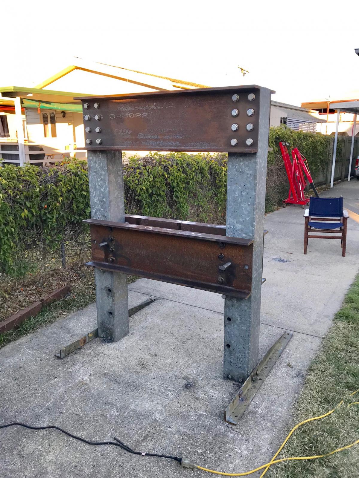
Once the top channels were installed I stood the press back up and basked in its glory :beer:
Attachment 27639
-
looks like your off to a good start
Doug
-
-
6 Attachment(s)
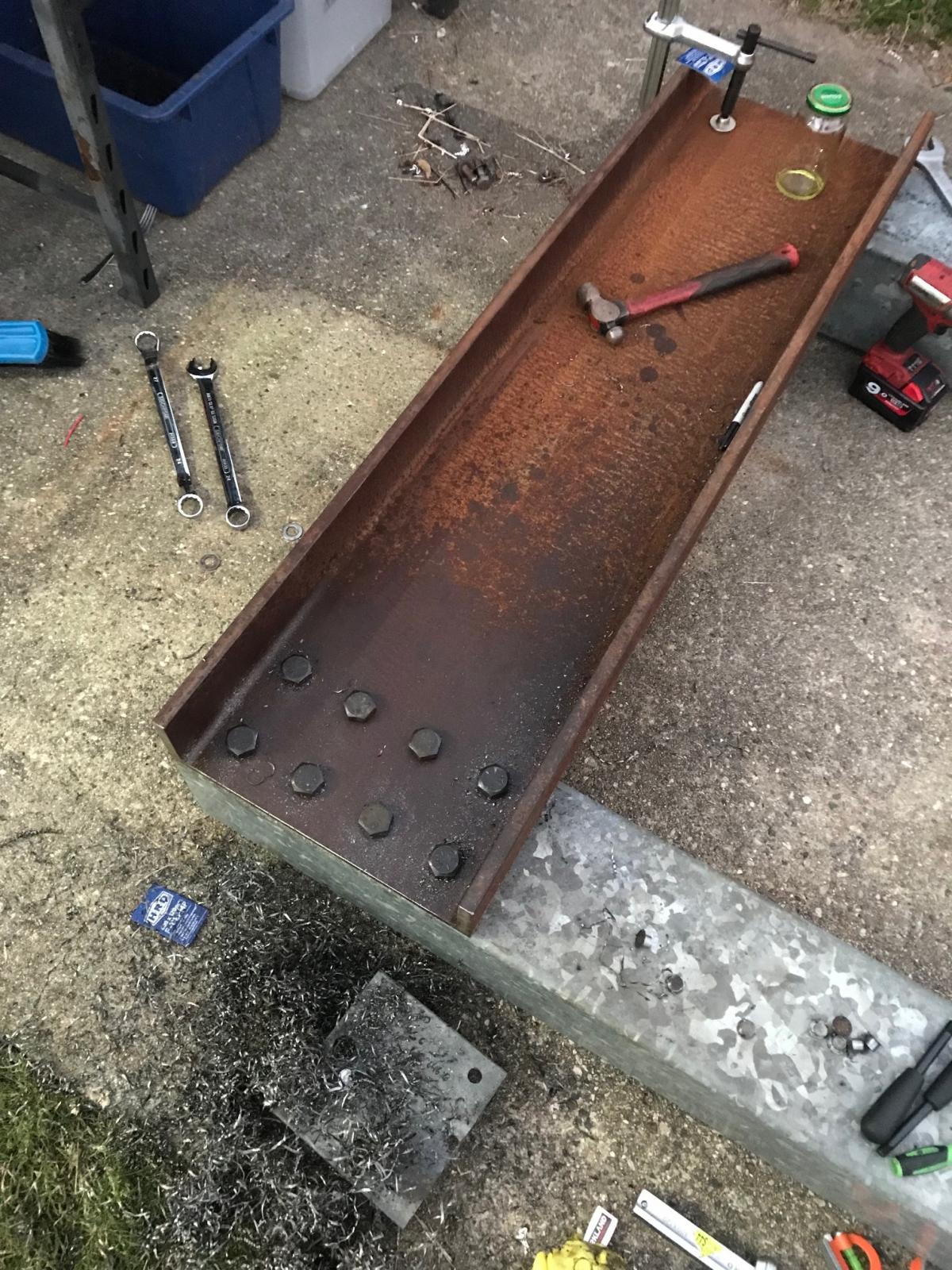
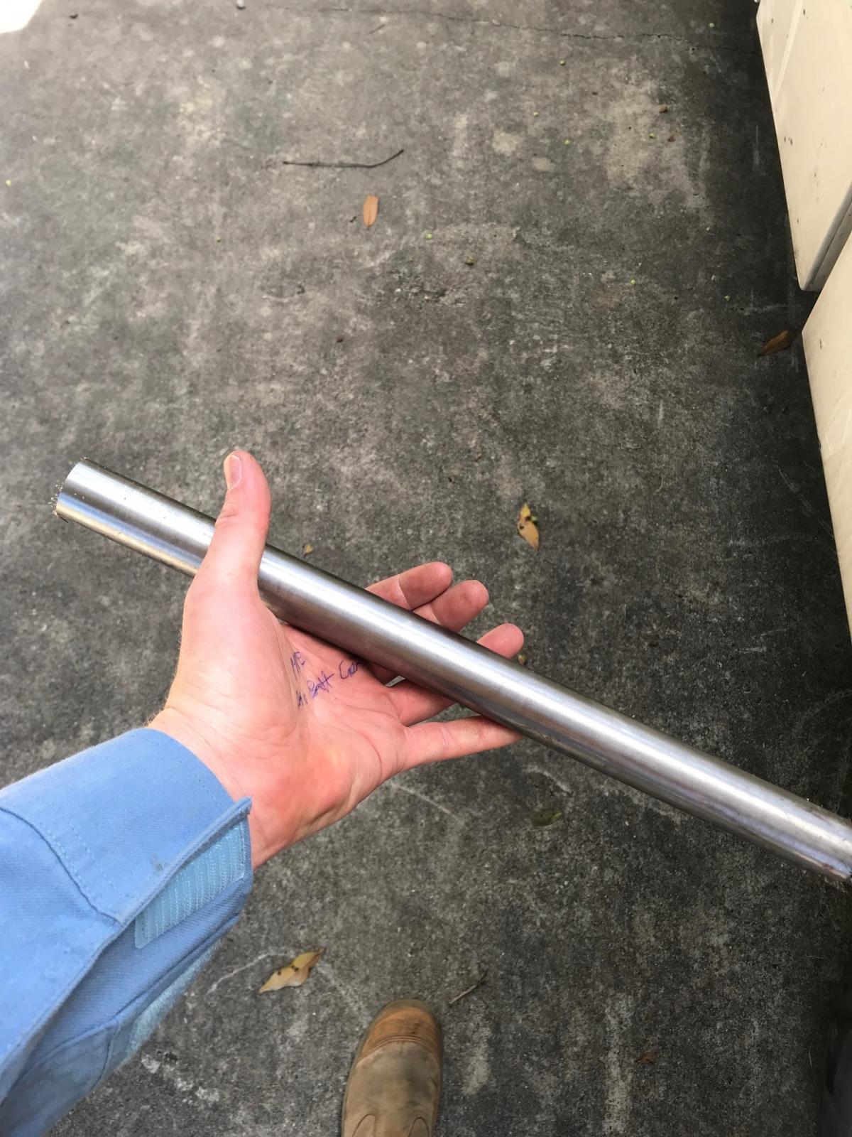
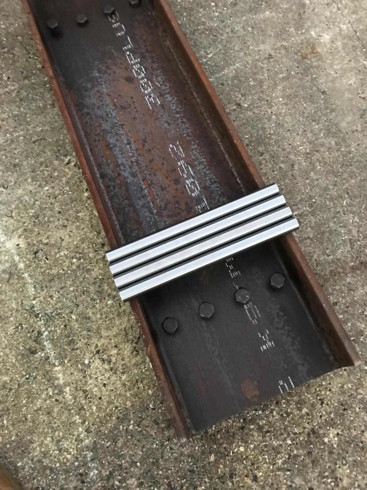
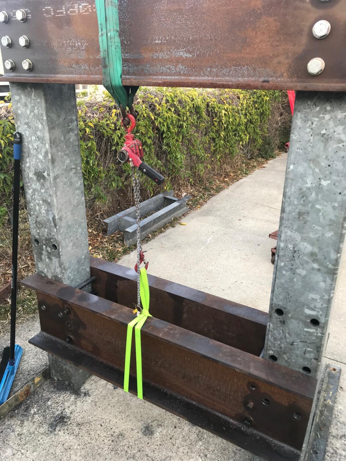
The next step I took was to buy the pins for the height adjustment of the press bed. I decided on some 30mm 4140 ground bar because it was accessible and far exceeded the shear strength required. I also picked up the 7/8UNF bolts to hold the two halves of the bed together.
Attachment 27781
I placed the two halves of the bed back to back to ensure the through holes would be as accurate as possible. One by one I drilled and installed the 7/8th bolts to again ensure the holes were as parallel as possible.
Attachment 27782
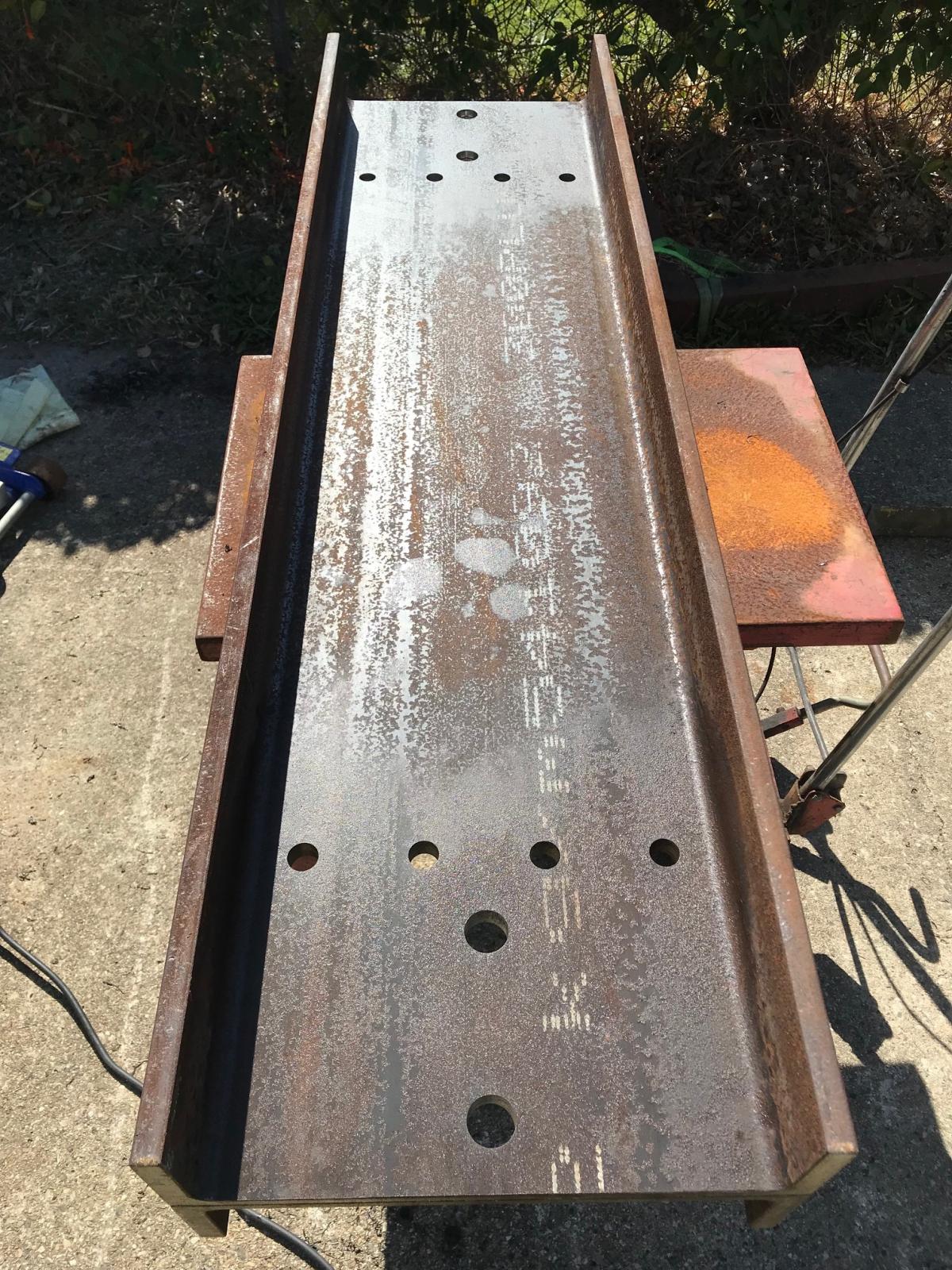
Then I marked out and drilled the 30mm holes for the pins.
Attachment 27783
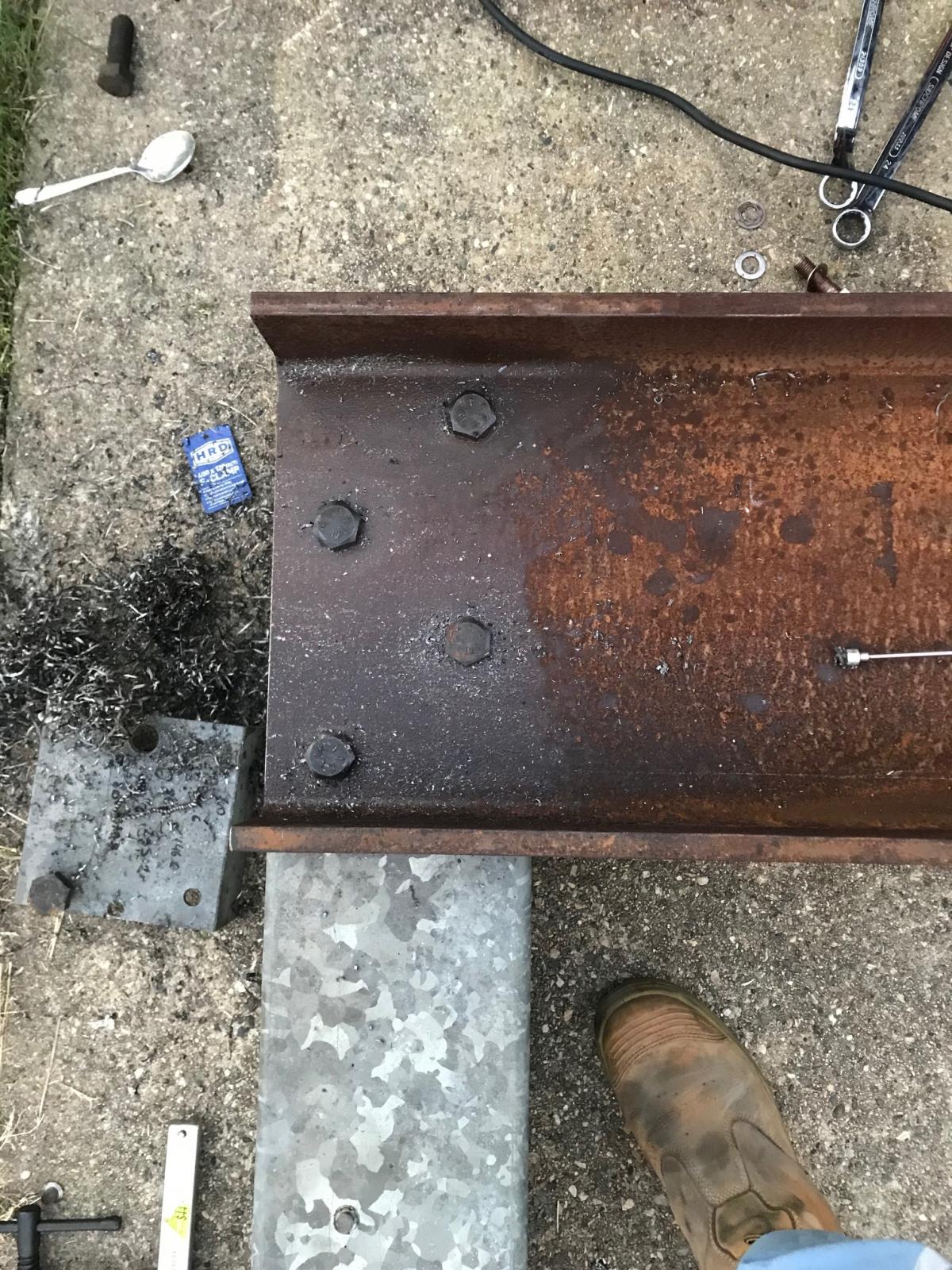
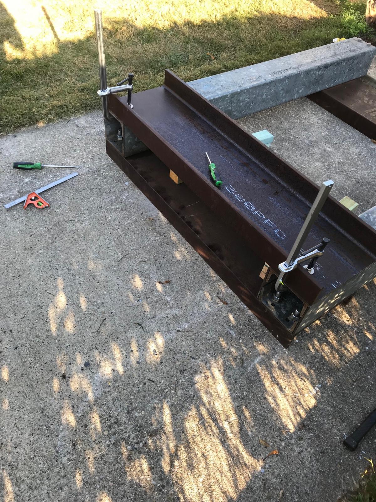
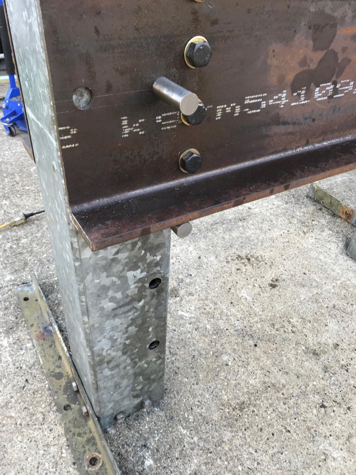
Drilling the uprights accurately was the next issue. I wanted the bed to be as square as possible. Starting at the bottom I assembled the bed around the uprights and measured everything to ensure it was sitting square before drilling the first set of holes through the uprights. Drilling the 30mm holes was a very time consuming task. Because I reinforced the box section with channel I had to drill through one layer, remove the plug and swarf and drill through the second before resetting the drill over the opposite hole and starting again. I installed the pins in the holes after drilling to ensure nothing was moving as I worked. Once the first set of holes were drilled I lifted up the bed, re-installed the pins in the holes and lowered the bed onto the pins, ready for the next set of holes. As you can see in the picture I drilled one set of holes first so I had the possibility of repairing any accidental mistakes.
Attachment 27784
Attachment 27785
The adjustable bed stays within 2mm of tolerance throughout the entire range of movement, more than accurate enough in my opinion. I lowered the bed and drilled the rest of the holes on the way back down.
Attachment 27787
Next step was to build the carriage to support the hydraulic cylinder.
-
5 Attachment(s)
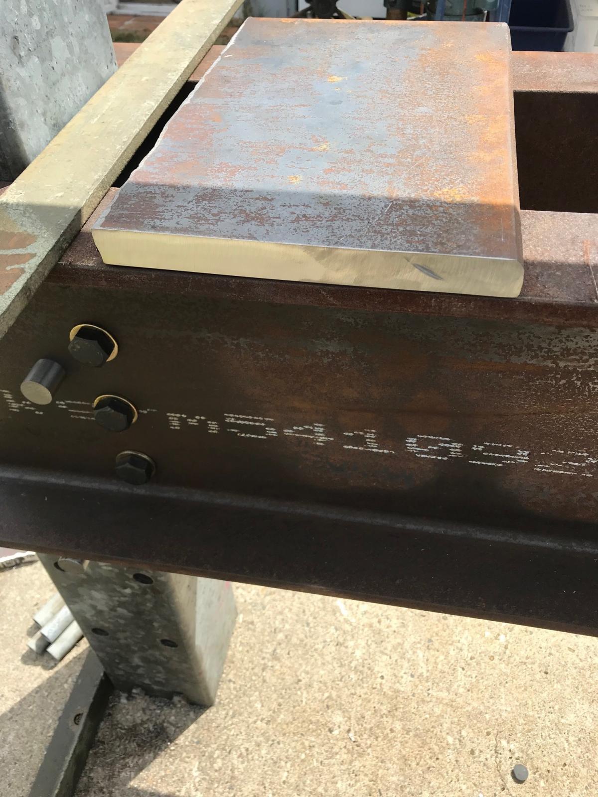
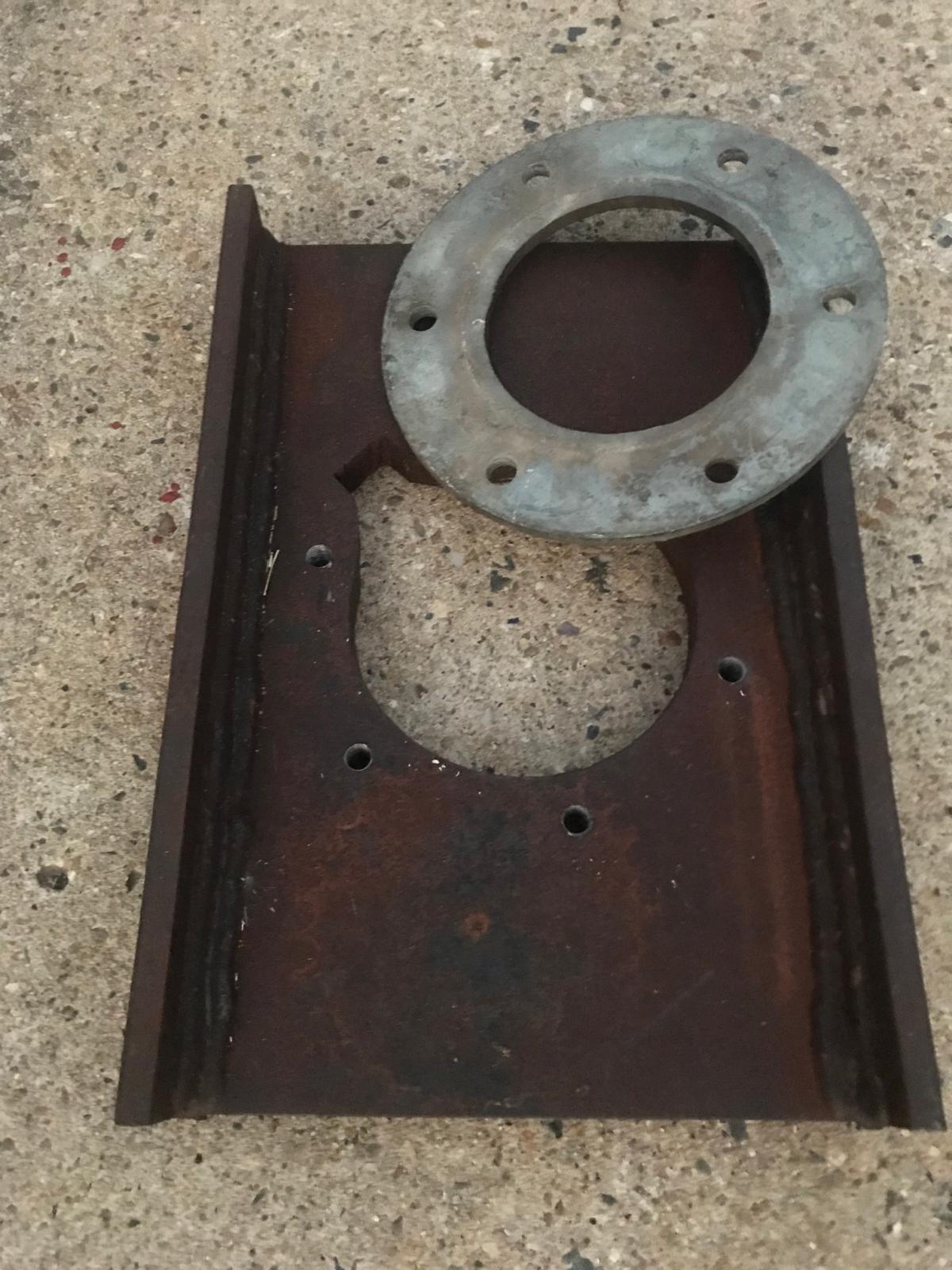
Because I have decided to re-purpose an old hydraulic cylinder I was limited in my mounting options. My best option was to take the press forces of the cylinder from behind the gland nut and use flange plate to stop the cylinder falling out. I started searching online and in scrap yards for some 30mm+ thick steel plate to hold the cylinder. I managed to find a 500 x 250 x 30mm off cut with some rough flame cuts at a scrap yard for $15. I dragged out the 9" grinder and cut it down to 400 x 250.
Attachment 27790
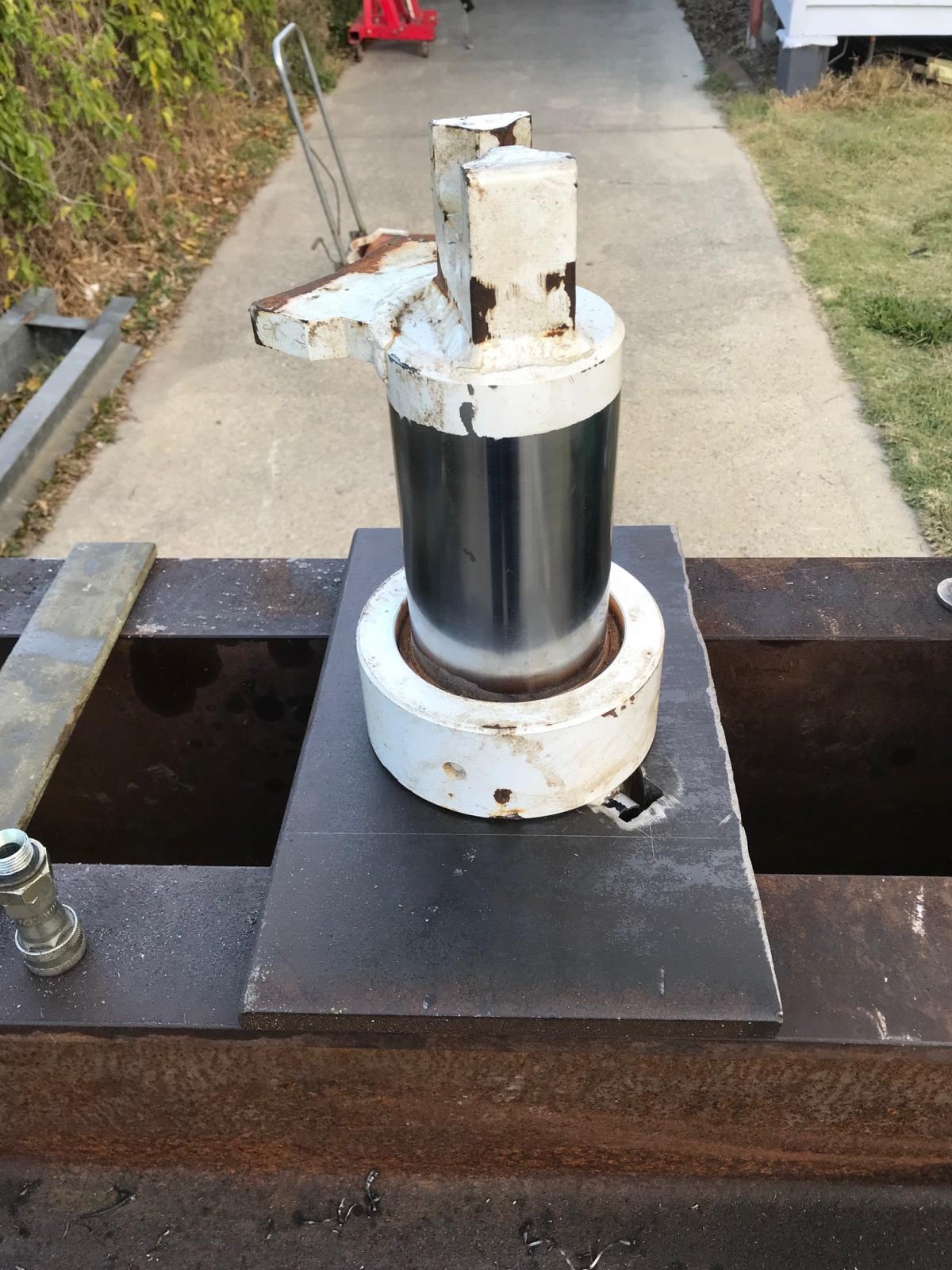
I marked out and drilled a 6' hole in the plate, then notched it out for the hydraulic fitting to pass through.
Attachment 27791
Attachment 27793
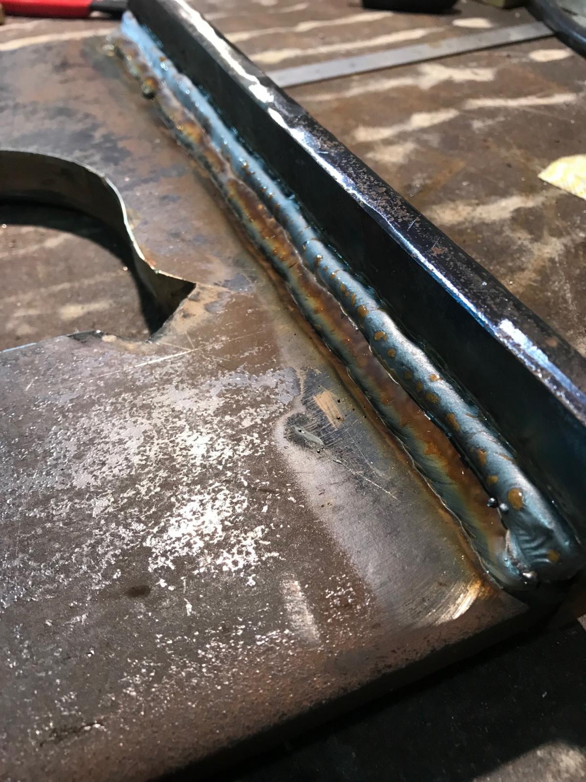
After drilling and notching the plate out I was having second thoughts about the strength of the plate. So I decided to reinforce it with some 10mm x 75mm flat bar.
Attachment 27792
I cut out a flange plate, drilled and tapped some M12 holes to retain the cylinder.
Attachment 27794
I wasn't happy with the end result and decided to look for a larger piece of plate to start again.