
 LinkBack URL
 About LinkBacks


I have this brand on my Wells-Index mill. On the Y axis and the knee (higher torque model).
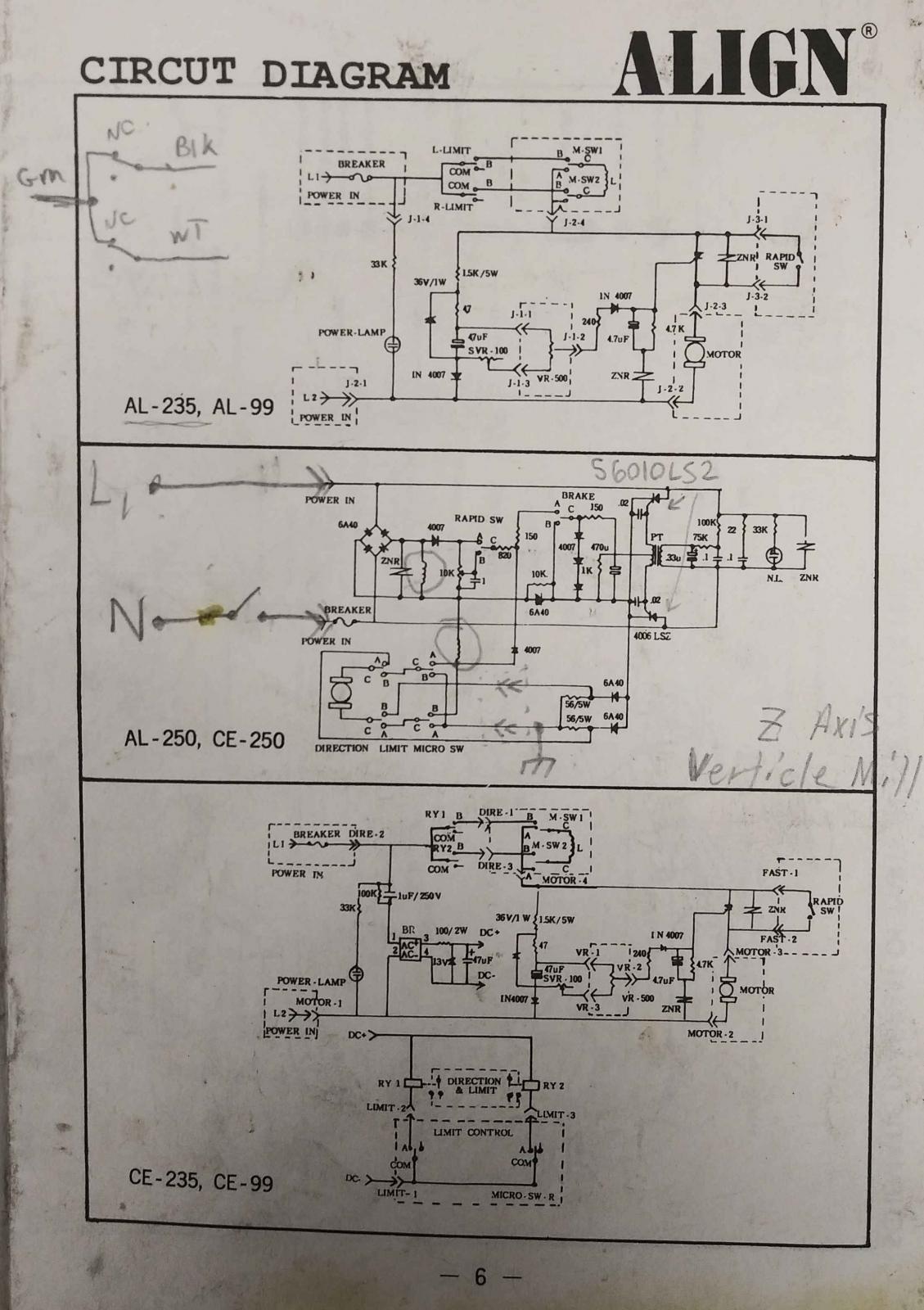
I have the schematic that came with the install manual.
The switches are single pole double throw. There are two of them, each one actuated by a left or right plunger that would be in the block, that is mounted to the saddle.
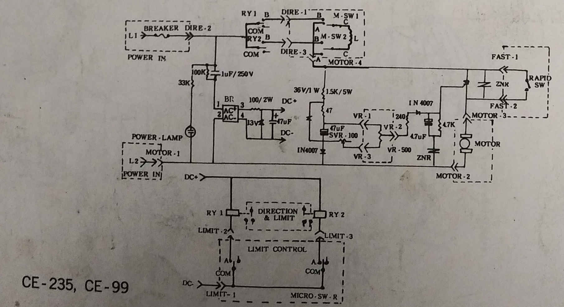
The schematic in the manual is for 3 different models. The bottom one is for the European CE-235 model, that inhibits AC line power going to those limit switches, and I assume it is applicable to your system. This runs a low voltage DC out (13V zener shunt regulator per the schematic). Sorry for the quality of this schematic. The three wires as shown in the schematic are Limit-1, 2, 3. It looks like it powers a pair of relays, RY1, RY2, which switch the line voltage.
If you open yours up, and see relays on the main circuit card, this is the right schematic. Other wise if it's like mine (USA delivery) the 2nd schematic is the one of interest. The top schematic is the Z axis knee schematic.
Hopes this helps.

 Reply With Quote

Bookmarks