Free 186 More Best Homemade Tools eBook:  
Get 2,000+ tool plans, full site access, and more.

User Tag List

Page 1 of 2 1 2 LastLast
Results 1 to 10 of 14

Thread: Lathe Carriage Stop Revisited

  1. #1
    Supporting Member jjr2001's Avatar
    Join Date
    Jun 2016
    Posts
    915
    Thanks
    1,182
    Thanked 2,045 Times in 553 Posts

    jjr2001's Tools

    Lathe Carriage Stop Revisited

    The link below is the original design that has been in use for quite some time. I have also made a 3rd type
    shown in the second link below. It can have as many stops as you want to make up.

    http://www.homemadetools.net/forum/m...0792#post73139
    http://www.homemadetools.net/forum/l...465#post107507
    I really like the one with the interchangeable stop rods. However it is not always on the lathe.

    My original two shown in the first link are ok but I wanted them to work a bit faster than the bicycle clamp.
    These are both configurable for a right side or left side carriage stop.

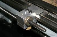
    I removed the bicycle clamp, threaded the body 1/4-20 and made a knurled knob. The knob is good and fast but not quite tight enough
    so I added 4 holes in each knob for a 1/4" tommy bar. The two allen cap screws that can be seen from the top side are only used for guide pins.They are not tight but quite loose. They do not need any adjustment when installing or removing the stop. I like the update since it is faster to set up than the bicycle clamp and the bike clamp could be a bit cumbersome to set up. The tommy bar has some surgical tubing on the end for a soft handle.

    Cheers, JR
    Attached Thumbnails Attached Thumbnails Lathe Carriage Stop Revisited-img_2371.jpg   Lathe Carriage Stop Revisited-img_2372.jpg   Lathe Carriage Stop Revisited-img_2374.jpg   Lathe Carriage Stop Revisited-img_2375.jpg   Lathe Carriage Stop Revisited-img_2376.jpg  

    Lathe Carriage Stop Revisited-img_2369.jpg   Lathe Carriage Stop Revisited-img_2370.jpg  

    186 More Best Homemade Tools eBook

  2. The Following 9 Users Say Thank You to jjr2001 For This Useful Post:

    Alan Purdy (Feb 12, 2019), high-side (Feb 11, 2019), Home-PC (Mar 19, 2021), Paul Jones (Feb 19, 2019), PJs (Feb 12, 2019), suther51 (Feb 11, 2019), Toolmaker51 (Feb 11, 2019), Tule (Feb 12, 2019), UncleBob (Feb 11, 2019)

  3. #2
    Supporting Member Toolmaker51's Avatar
    Join Date
    Feb 2016
    Location
    Midwest USA
    Posts
    5,331
    Thanks
    7,042
    Thanked 2,980 Times in 1,893 Posts

    Toolmaker51's Tools
    Quote Originally Posted by jjr2001 View Post
    The link below is the original design that has been in use for quite some time. I have also made a 3rd type
    shown in the second link below. It can have as many stops as you want to make up.

    My original two shown in the first link are ok but I wanted them to work a bit faster than the bicycle clamp.
    These are both configurable for a right side or left side carriage stop.

    I removed the bicycle clamp, threaded the body 1/4-20 and made a knurled knob. The knob is good and fast but not quite tight enough
    so I added 4 holes in each knob for a 1/4" tommy bar. The two allen cap screws that can be seen from the top side are only used for guide pins.They are not tight but quite loose. They do not need any adjustment when installing or removing the stop. I like the update since it is faster to set up than the bicycle clamp and the bike clamp could be a bit cumbersome to set up. The tommy bar has some surgical tubing on the end for a soft handle.

    Cheers, JR
    You can remedy single point clamping with a fulcrum. Drill and tap body or clamp plate for a small set screw, allowed to poke out. An alternate mills a bit heavier plate for a 'toe' at outboard end and clamp, and with surfaces parallel.
    Quite sure tommy bar will get lonely as a hermit.

    2000 Tool Plans
    Sincerely,
    Toolmaker51
    ...we'll learn more by wandering than searching...

  4. The Following User Says Thank You to Toolmaker51 For This Useful Post:

    Paul Jones (Feb 20, 2019)

  5. #3

    Join Date
    May 2018
    Posts
    12
    Thanks
    0
    Thanked 2 Times in 2 Posts

    Carriage stops.

    I need plans for carriage stops. Mine need to be larger than for a mini lathe. I need to build a pair for a 15” x 60” Southbend Lathe. Any suggestions. Can you email plans for yours? I can try to upsize them.

    Thanks,
    Michael Sutton
    Midan Gunsmithing
    suttonmike72@yahoo.com

  6. #4
    Supporting Member jjr2001's Avatar
    Join Date
    Jun 2016
    Posts
    915
    Thanks
    1,182
    Thanked 2,045 Times in 553 Posts

    jjr2001's Tools
    Ahhhhh thanks TM. That is what I missed when I changed the clamp. I do not have the clamp pad parallel to the body so the clamp is just hitting on the edge of the lathe bed. Thanks for the tip. I will modify them.

    Cheers, JR

  7. #5
    Supporting Member jjr2001's Avatar
    Join Date
    Jun 2016
    Posts
    915
    Thanks
    1,182
    Thanked 2,045 Times in 553 Posts

    jjr2001's Tools
    Quote Originally Posted by Suttmike1 View Post
    I need plans for carriage stops. Mine need to be larger than for a mini lathe. I need to build a pair for a 15” x 60” Southbend Lathe. Any suggestions. Can you email plans for yours? I can try to upsize them.

    Thanks,
    Michael Sutton
    Midan Gunsmithing
    suttonmike72@yahoo.com
    Here are a bunch of them, may have plans or build pictures:
    Homemade Tools Search: carriage stop - HomemadeTools.net


    Nice one by Rossbotics:
    http://www.homemadetools.net/forum/l...age-stop-69874

    Another:
    http://www.homemadetools.net/forum/n...the-stop-66194

    One more:
    Tom's Techniques – Micrometer Carriage Stop

    Cheers, JR
    Cheers, JR

  8. The Following 2 Users Say Thank You to jjr2001 For This Useful Post:

    Home-PC (Mar 19, 2021), Paul Jones (Feb 20, 2019)

  9. #6
    Content Editor
    Supporting Member
    DIYer's Avatar
    Join Date
    Aug 2013
    Posts
    3,056
    Thanks
    772
    Thanked 1,852 Times in 1,653 Posts


    Thanks jjr2001! We've added your Lathe Carriage Stop to our Lathe Accessories category,
    as well as to your builder page: jjr2001's Homemade Tools. Your receipt:


  10. The Following 2 Users Say Thank You to DIYer For This Useful Post:

    Home-PC (Mar 19, 2021), jjr2001 (Feb 16, 2019)

  11. #7

    Join Date
    Dec 2018
    Posts
    3
    Thanks
    0
    Thanked 0 Times in 0 Posts
    I want to know if you have a hard stop attached to the way, does the carriage pop the split nut open and disengage from the lead screw? I have an old SB 9C and I am not about to try and crash it into a hard stop to find out....

  12. #8
    Supporting Member jjr2001's Avatar
    Join Date
    Jun 2016
    Posts
    915
    Thanks
    1,182
    Thanked 2,045 Times in 553 Posts

    jjr2001's Tools
    Quote Originally Posted by JBMauser View Post
    I want to know if you have a hard stop attached to the way, does the carriage pop the split nut open and disengage from the lead screw? I have an old SB 9C and I am not about to try and crash it into a hard stop to find out....
    Of course I have a hard stop attached to the lathe ways. That is exactly what the picture shows.
    I only use it during manual feed and my nuts are still intact.
    The best way to screw up your lathe would be to use power feed into a hard stop!

    Cheers, JR

  13. #9
    Supporting Member Toolmaker51's Avatar
    Join Date
    Feb 2016
    Location
    Midwest USA
    Posts
    5,331
    Thanks
    7,042
    Thanked 2,980 Times in 1,893 Posts

    Toolmaker51's Tools
    Quote Originally Posted by JBMauser View Post
    I want to know if you have a hard stop attached to the way, does the carriage pop the split nut open and disengage from the lead screw? I have an old SB 9C and I am not about to try and crash it into a hard stop to find out....
    Oh yeah, the carriage will split the half nut open all right...once!

    Hard stop = manual use only.
    No bedway clamps have the means of disengaging feed rod or lead screw, normally. There are a few, MoriSeiki, Okuma and others, typically larger lathes with movable cams that trip a detent extending from bottom of carriage. Some locate on rigid cast drip pans, others use a manually indexed rod below whatever feed, lead, and clutch shaft. Those only function to halt the feed of carriage along ways.

    Here on HMT.net, a very creative member 'gatz' posted his ultra positive threading kickout, pneumatic no less, astounded all of us. Perfect threading right up to a shoulder, at real RPM's. It would easily function feed-wise if reoriented to trip feed lever.
    http://www.homemadetools.net/forum/l...t-set-up-68878
    Sincerely,
    Toolmaker51
    ...we'll learn more by wandering than searching...

  14. The Following User Says Thank You to Toolmaker51 For This Useful Post:

    jjr2001 (Feb 19, 2019)

  15. #10
    Supporting Member jjr2001's Avatar
    Join Date
    Jun 2016
    Posts
    915
    Thanks
    1,182
    Thanked 2,045 Times in 553 Posts

    jjr2001's Tools
    Thanks TM51, great explanation and I agree 110%. I liken it to driving your car into a wall at 60 mph, not much left.
    Gatz made a very nice setup for his Jet lathe. Blood pressure starts to rise as the arm gets close to the stop and then Click,
    blood pressure back down!

    Cheers, JR
    Back to the shop.

Thread Information

Users Browsing this Thread

There are currently 1 users browsing this thread. (0 members and 1 guests)

Tags for this Thread

Bookmarks

Posting Permissions

  • You may not post new threads
  • You may not post replies
  • You may not post attachments
  • You may not edit your posts
  •