wondering if anyone has made or has plans for a tailstock that I can use or modify for a homemade log lathe?
Printable View
wondering if anyone has made or has plans for a tailstock that I can use or modify for a homemade log lathe?
Hi revid, I don't know if mine will help you or not, I don't have plans or such as my lathe build was made "ad-hoc" if you know what I mean. Here is a link to my thread on a log lathe build in a welding forum that I belong to. It may give you some ideas for your tailstock build. The tail stock section is from Pic 31-40 which is about 3/4 of the way though the thread. Hope it helps.Quote:
Originally Posted by revid
Cheers
Ed.
Built a wood lathe - lots of pics. | MIG Welding Forum
hi,Quote:
Originally Posted by revid
in my opinion,it would be far cheaper to buy a lathe tailstock on Ebay,ETC.
Than it would be to have one made.
I do not know how big the logs will be,that you want to turn?
But if you can get your hands on a large engineering lathe tailstock,and adjust the height with the use of an adapted wooden block,to the same centre height as your headstock,it should handle the logs you want to turn.
Just one other thing i have found,works well.
If you bolt your lathe to a solid floor with chemical bolts & put a hard rubber mat under the headstock & tailstock (lathe in one piece).
It greatly reduces the vibration caused by a heavy lathe.(I have a wadkin RS 10 feet long).
hope this helps!
I don't have one built yet so anything I say is just theory at this point. I have some large logs I want to turn. They are about 5' long and about 1' in diameter. One of them has been hollowed out by animals. I intend to make a guest book stand out of it by turning the outside, putting a top and bottom on it and putting a clear finish on the whole thing. My log is from a catalpa tree that had been in our front yard for at least 50 years.
Now to your question. Somewhere I saw a lath a guy built using the spindle from a small compact car. My idea is to use two of them, one for each end. Make some angle iron brackets and lag both them to an old railroad tie. The head stock will just have a home made pulley driven by what ever I come up with for a motor and speed reduction scheme. I intend to fasten a round piece of 3/4" plywood to each end of the log and make mounting holes in the plywood that will match the lugs on the hubs. I intend to run the logs very slow and will machine them using a homemade guide to which I will a standard router to face off the bark and get down to the nice wood underneath. I have used this method on smaller similar projects and it has worked very well. Once I get the log like I want it I will take my belt sander and clean up the log after which I will use my orbital sander and get the finish surface like I want it.
As I mentioned I did a project similar to this some time ago only it was somewhat smaller. It was about 10" in diameter and about 4' long. It was made up of many small boards I made out of old pallet wood which was then cleaned up and shaped with bird's mouth joints on one side then all glued together like a ships mast. It came out very nice and when finished it looked like a very nice piece of furniture.
Jerry
Nice job Ed.In pics 4 & 5,what did you use to make those two pieces? In pic 8 I am guessing that once you turn handle that pushes one rod thorough the other. I see you use a live center on end,whet did you use on the headstock? My lathe turn very slow, I have a planer head mounted on a carriage that travels the length of the log,cutting as it goes.I have the carriage controller via speed controller and relays. Its the same carriage that I use to travel my bandsaw which is mounted on it,I just turn the speed down on carriage.I have a gear reduction to turn the logs and have a 5 hp electric 3450 rpm motor to "plane" the logs round. My main issue is getting something for a tailstock that once I lock it in place I need something that will push tailstock into log and keep it there. I am thinking about a ram from a horizontal hydraulic jack.That way once its lock I just crank the handle and push tailstock forward into log.What do you think?? I also like the idea of side axles with pillow block bearings but how to push center into log?Quote:
Originally Posted by Ed.
JP,did you machine down the axles to mount pillow block bearings or something like that?
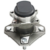
There is no axle involved. Only the hub and bearing. See photo
Attachment 17541
JP
JP,what pic and where?
There is no axle involved. Only the hub and bearing assembly. See photo
Attachment 17548
JP
oh,ok thanks
Hello, I received an email asking if I could offer any help to your question. I'm not sure that what I am doing is on the same page as your project, I'm basically building a customised double spring pole lathe inspired by Roy Underhill's design. It's been on hold for a while, had lots of more important things to do, so haven't got to the point of designing and building the tailstock yet, but if you check out part 4 of my build you will see my first, less than successful attempt at a headstock. The only thing that actually went wrong was the diameter of the spindle that I used, it was much to large and severely slowed the spinning rate down. The next step will be to replace it with one of much smaller diameter.Quote:
Originally Posted by revid
However, if you take notice of how I've constructed the headstock you might see how I will be designing the tailstock. It will comprise of one piece of wood cut similar to the piece used in the headstock, and another about half the height, and a similar distance inbetween, with smaller pieces joining them together, and a wedge used underneath to lock it down, kind of like how I constructed the frame of the lathe itself. Anyway, if you click on the link below you might just find something that will get you thinking, and hopefully you'll come up with a good solution.
Double Spring Pole Lathe – Woodworking by David
Best wishes,
David.
Hi Revid,Quote:
Originally Posted by revid
I am not sure that that you are referring to the correct pic numbers,
Pic 4 & 5 are just the bed I beams and the cross beams which will support the bed
Pic 8. is the double pulley which connects to the motor.
I think that you maybe referring to the following?
33. Welded a 30mm x 3.5mm nut I made inside a 8mm x 60mm pipe for the tool post holder. This becomes the sleeve for sliding the threaded MT3 holder in and out.
34. Tool post holder and sleeve.
38. Tool post handle with stainless tube handle sleeve.
39. Tool post locking nut.
37. Tool post mostly assembled
The planer idea that you have is a modification that I had in mind to do at a later date when time permits, using a mounted wood router on rails to mainly to take the excess wood from a log to make it cylindrical without having to use wood chisels to do that, using the VSD I can rotate an unbalanced log slowly and just use the router to remove the excess. Using the VSD, the slower I go the less torque I have, currently I have a 2 step range, High and Low and variable via VSD. so I am thinking about redoing the motor setup and moving the motor outside and putting in a multi step pulley system to vary the RPMs of the faceplate without loosing torque, and then using the VSD to fine tune the RPM's within the step range.
I don't think I can give you any ideas about the hydraulic tail post, with mine I have to physically push the entire back end post towards the log then clamp it down using bolts (Pic 39) to the middle of the bed, and then using the screw to push the live centre in to the log end. Once I have the live centre embedded into the log end I then just lock the nut on the thread and that keeps it all in place. If I understand your meaning, you could use the hydraulic ram to push the entire back end close to the log end and then just use the setup I used to screw the live centre into the log. For me using hydraulics is a lot of effort and cost to engineer something just to do what that I can do manually in about a minute, undo two bolts, slide post, clamp two bolts, adjust live centre, done.