
 LinkBack URL
 About LinkBacks


About a year ago I bought a 1919~1920 JD Wallace 16 inch bandsaw. The man selling it was an retired contractor foreman that been collecting all kinds of tools. He was taking back his garage space, I ended up getting this saw for $145 with a couple car loads of other stuff. He was happy to pass it on to someone that would use it and get enough room to maybe get a car in his garage. I was happy to get a real bandsaw.
After getting help from a friend moving the 350lbs saw ( considered portable in its time) I found out the working saw was going to be a project. The first time I plugged the saw in I heard a shrill squeal. The problem was the motors brush system had been jerry rigged. the motor is cast into a housing specific to the saw so the problem isn't as easy as swapping a motor on a 4x6 bandsaw or something like that. I have given up on finding ( for the time being) an original replacement.
my back up plan has been to use a DC treadmill motor. the tricky part is the mounting of the motor as my current challenge. I would like to brainstorm with the homemade tools group as to a good solution.
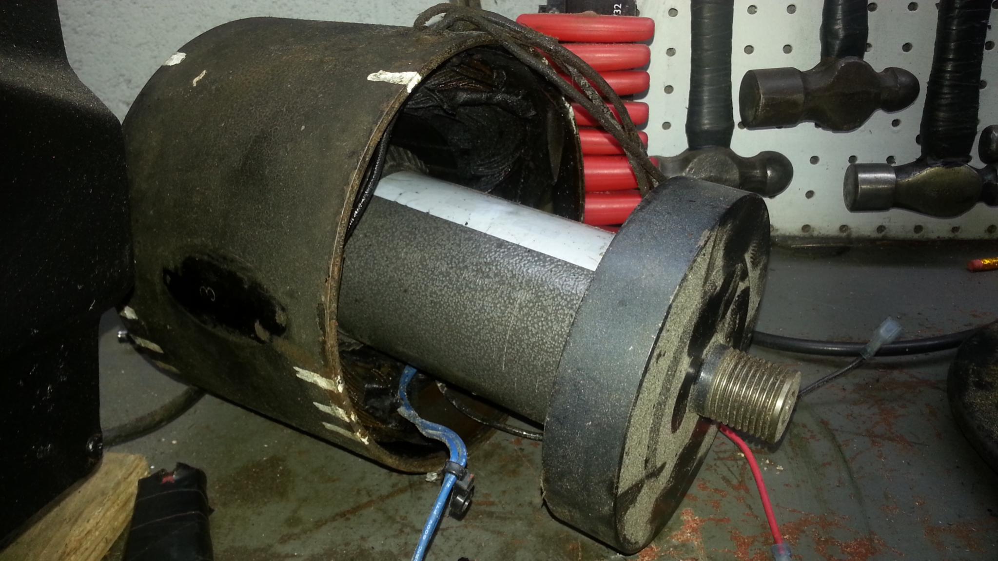
I want to mount the DC motor inside of the ac motor as pictured above roughly.this way the housing could in the future be restored to original. (If it comes down to it I will forgo this idea) what kind of mount should I make? would a pair of plywood doughnuts with the motor in the middle work? Any other suggestions criticisms would be great. feel free to chime in even if its just a thought


 Reply With Quote

Bookmarks