
 LinkBack URL
 About LinkBacks


I recently posted some adventures that I had cutting the back end off a lathe head stock. http://www.homemadetools.net/forum/i...515#post135903
I was asked how I held the spindle for unscrewing chucks without any back gears. Well I never use back gears for that job, my mechanical sympathies cringe at the mere thought of it, it seems so brutal. That might come as a surprise from someone who cuts a lathe head in half without a second thought but I really hate abusing mechanical devices.
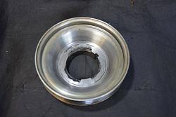
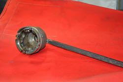
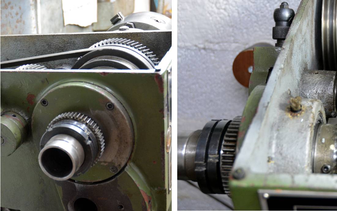
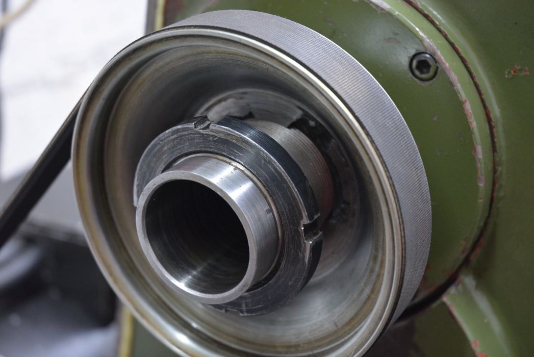
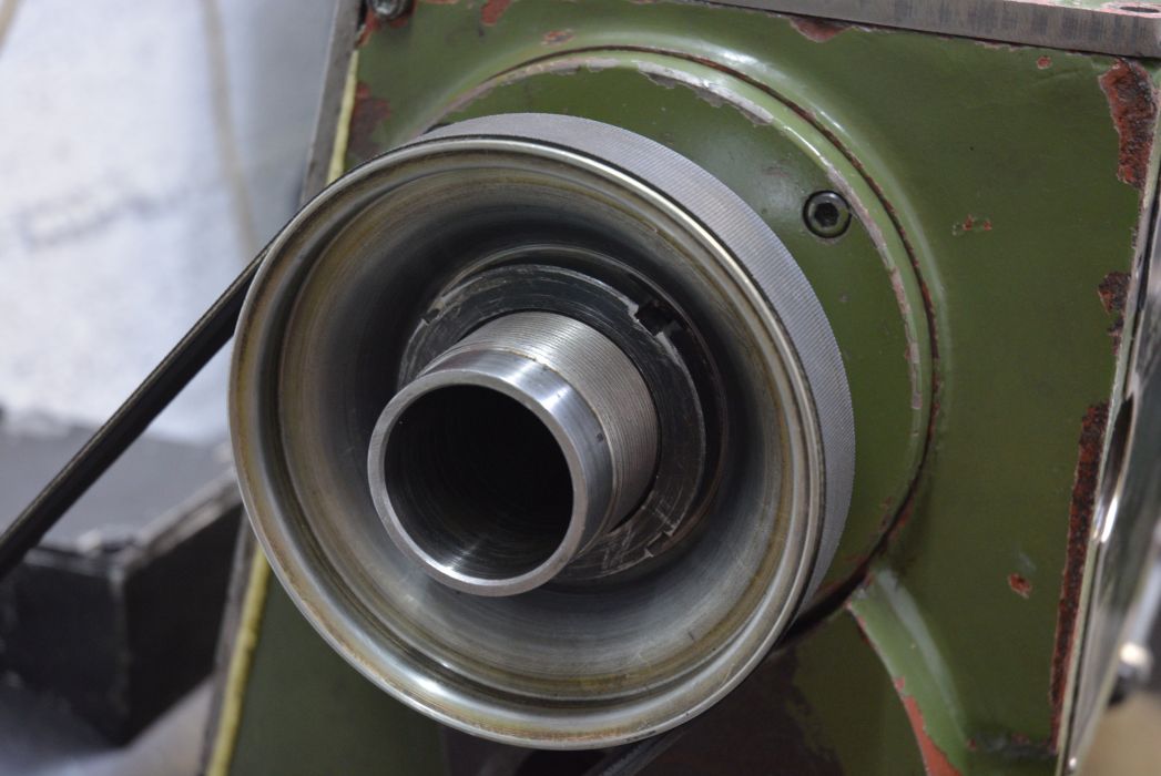
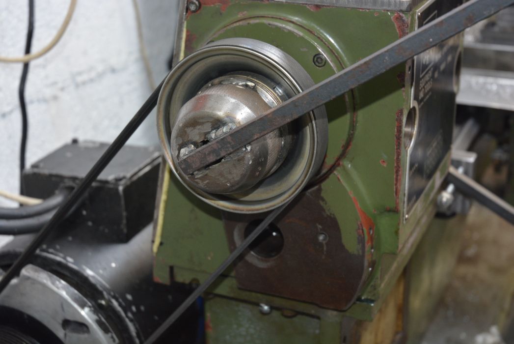
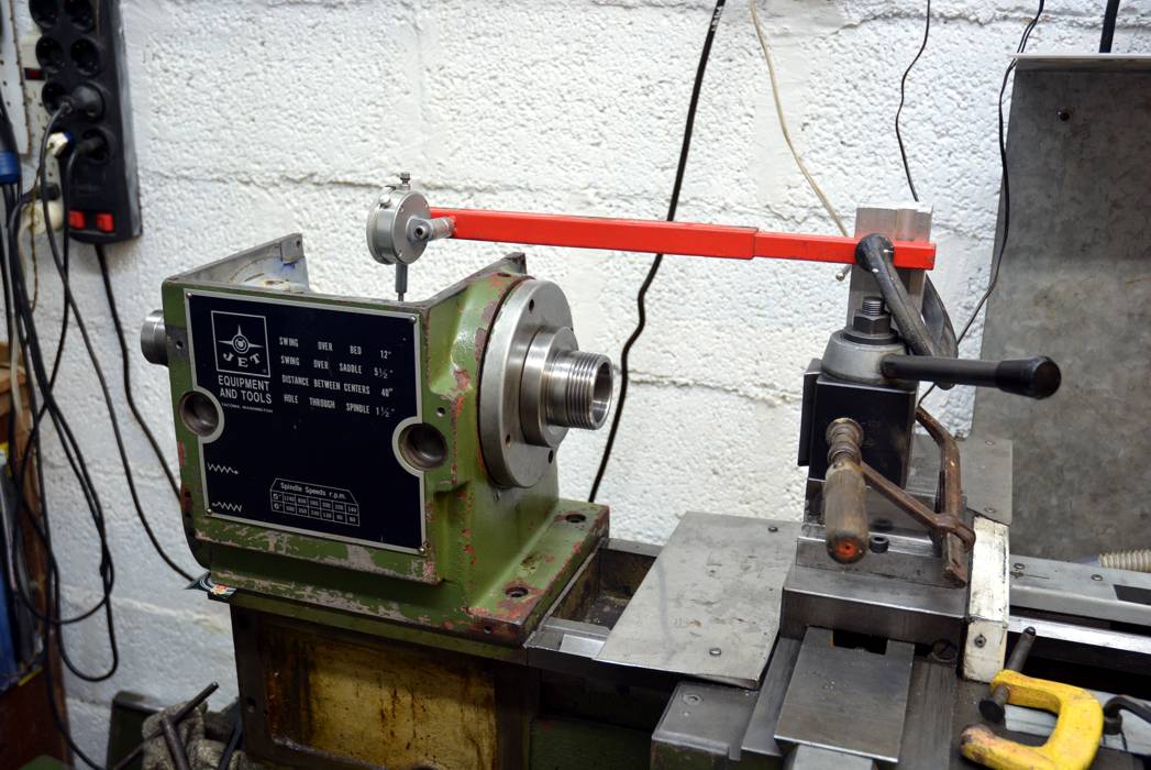
My lathe came with a locking hole in the nose part of the spindle as shown next.
Click images for fullsize version.
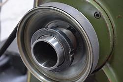
I built a simple tool to securely locate in that hole using a G-clamp to save work. It rests against the foot of the lathe head and provides a very solid lock on the spindle and chucks unscrew easily. I hold it by hand when screwing a chuck on. There is no need to tighten chucks very tightly, that just makes it harder to unscrew.
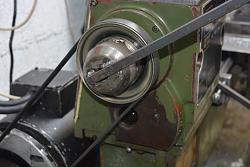
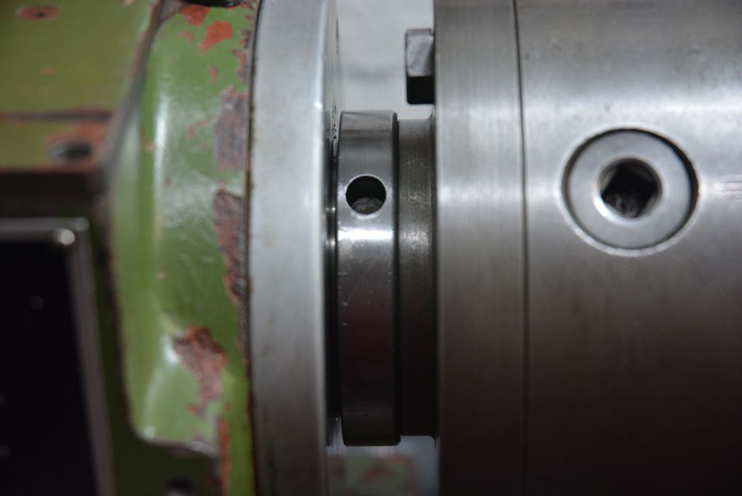
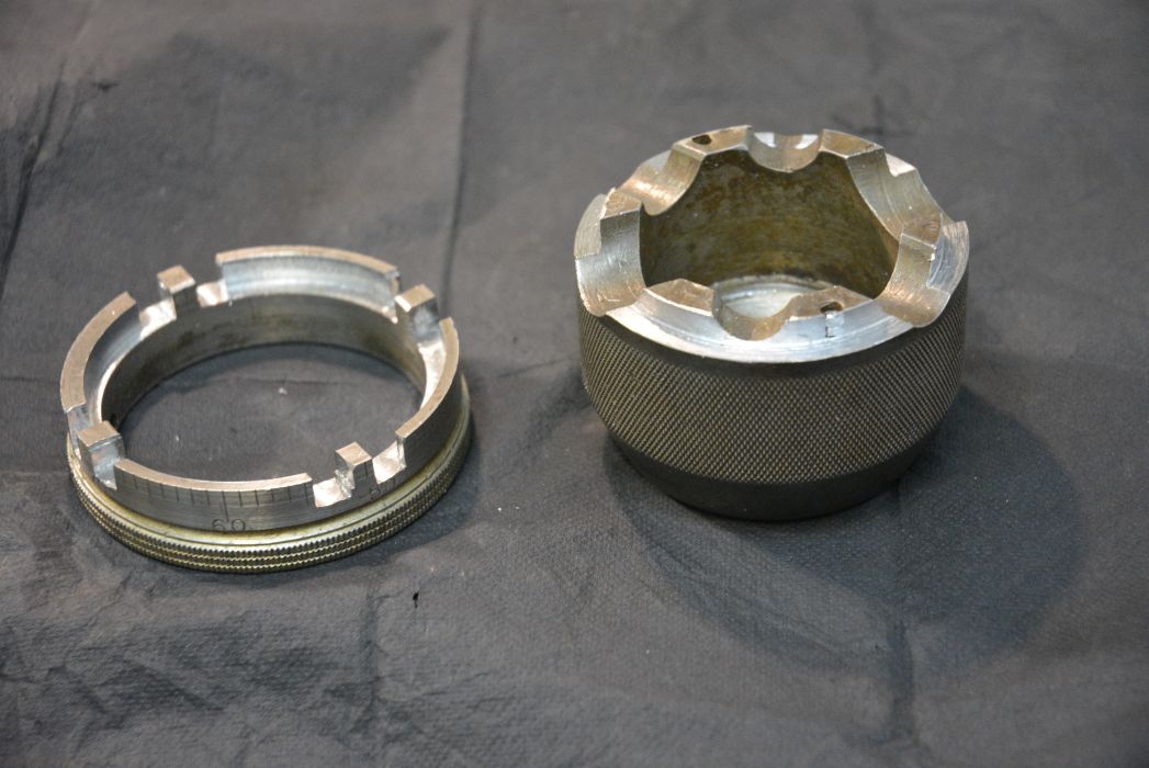
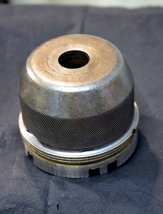
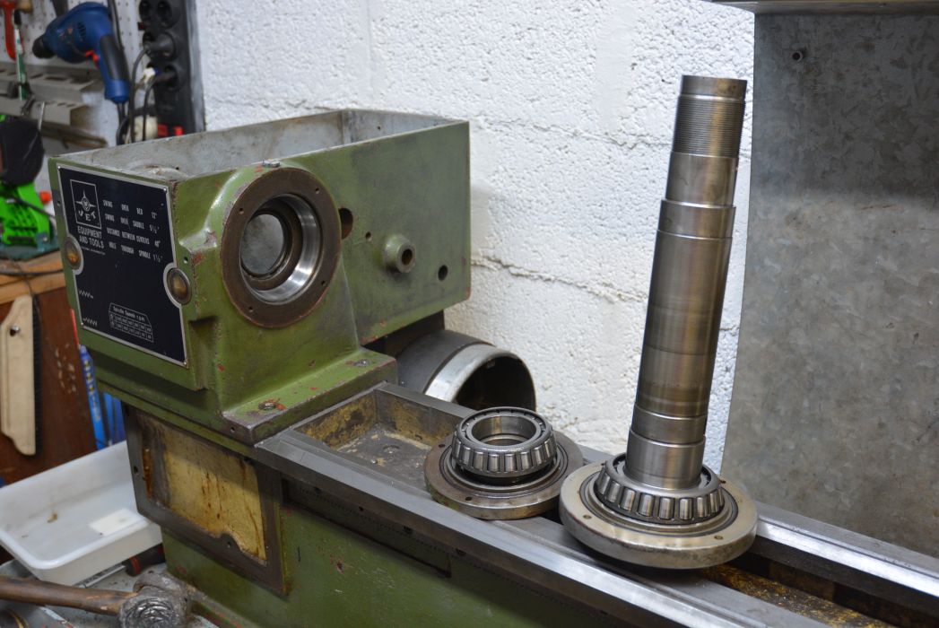
When doing the butchery on the head stock I needed to remove the rear taper roller bearing off the spindle. I also wanted to inspect the bearings and seals. There is a castle nut and an identical locking nut which provide preload to the bearings and hold the spindle assembly together, as shown below.
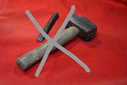
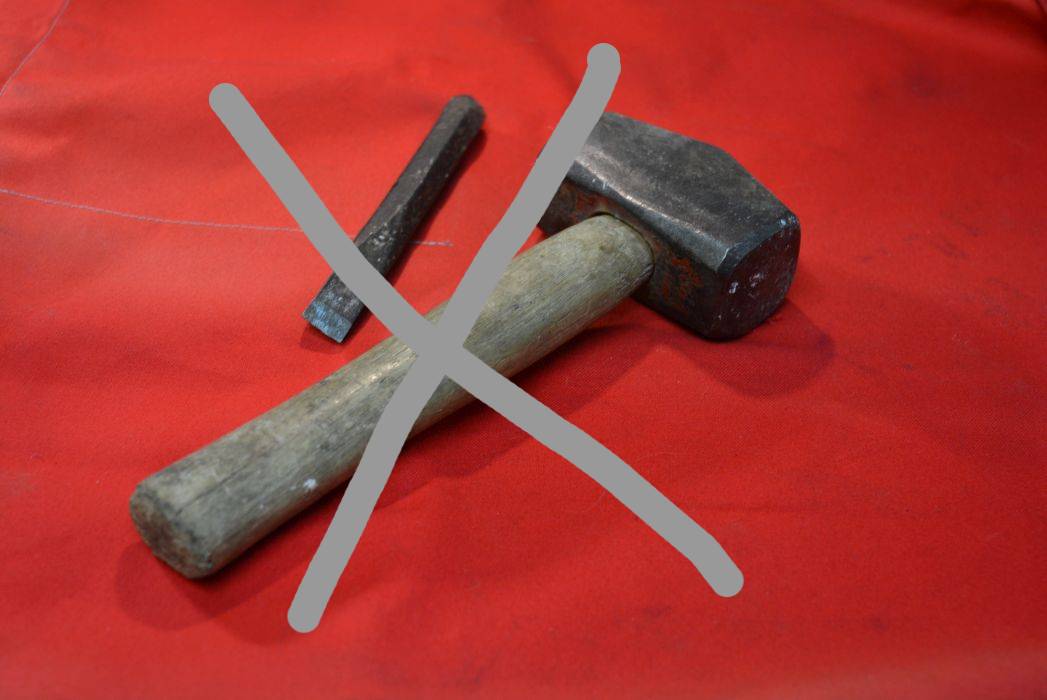
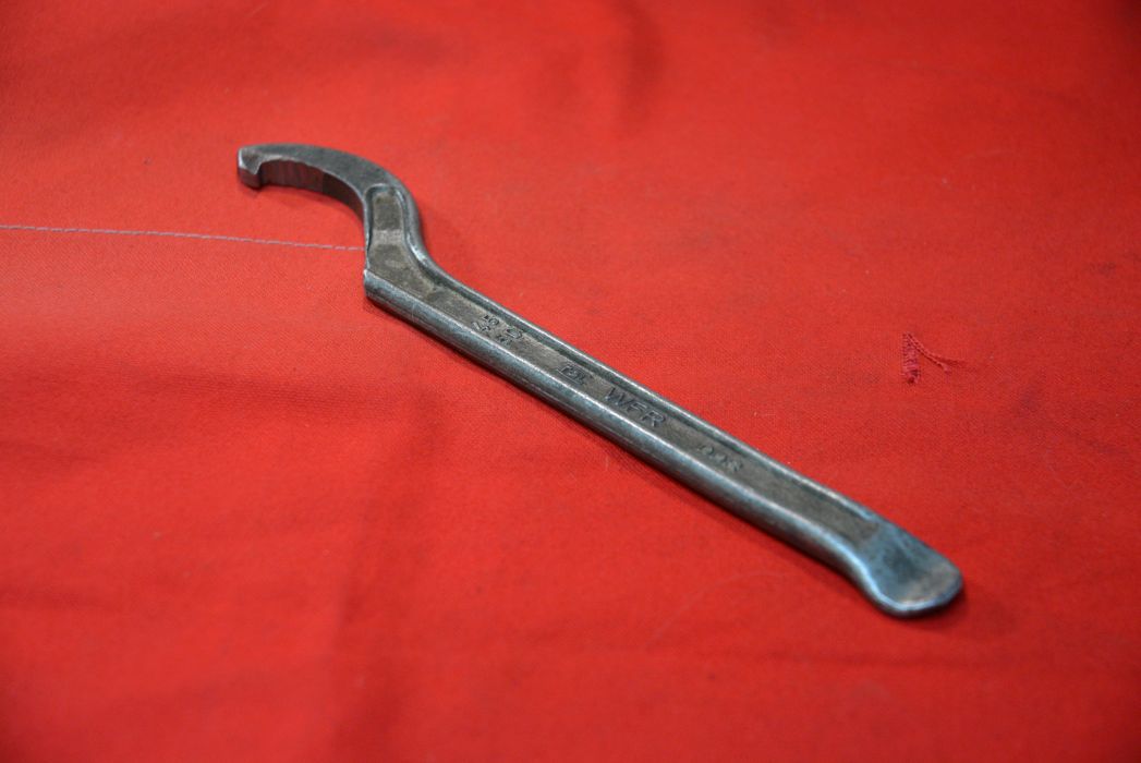
I have seen people use a hammer and cold chisel to tighten and loosen this type of nut but in my book that is a method best reserved for emergencies and in the field when a proper tool nor the facilities are not available. This is doubly true when the nuts are on a spindle with bearings like a lathe. A hook spanner is much better but unless it is a very good fit it can slip off the nut. I had such a spanner which I modified for a better fit but although I was able to unscrew the nuts it was difficult to keep it in place.
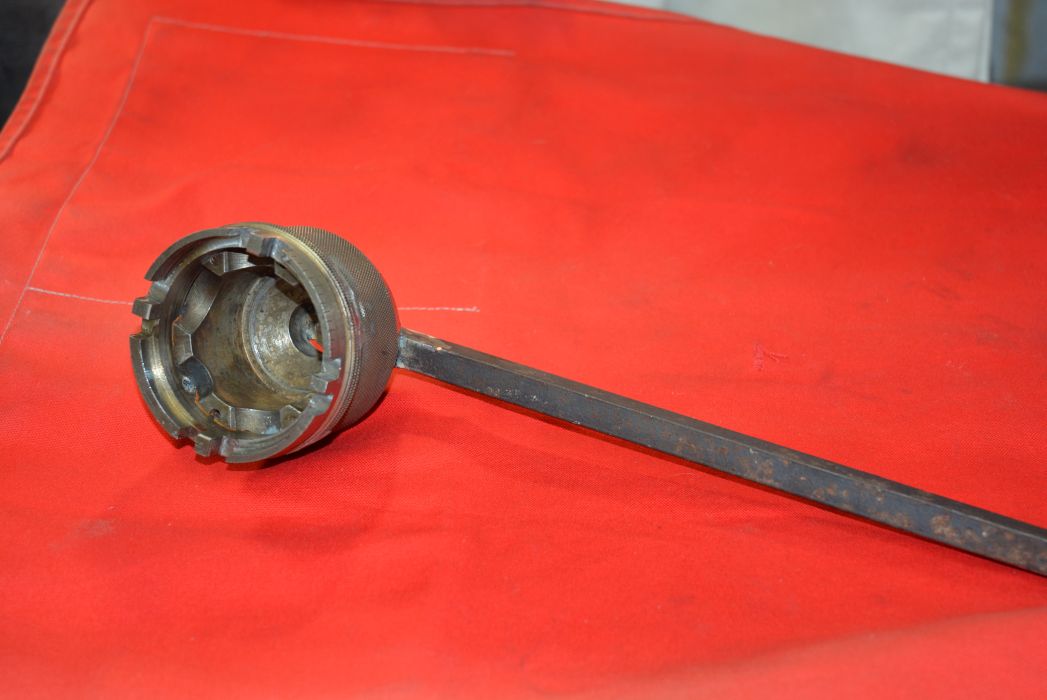
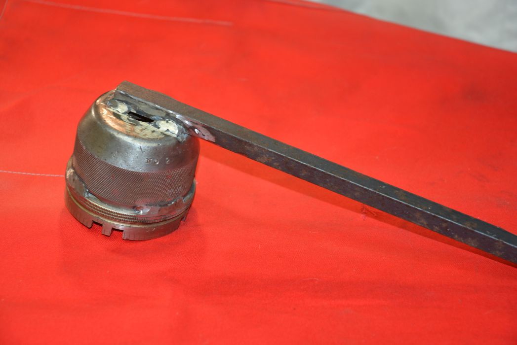
As explained in my previous post I changed the motor and drive system from internal to external belt and pulleys. The top pulley on the spindle was from a car water pump drive and was heavily dished. The dish disallowed the use of a hook spanner or other type of flat spanner.
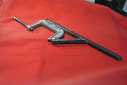
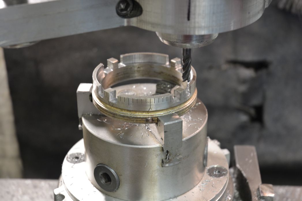
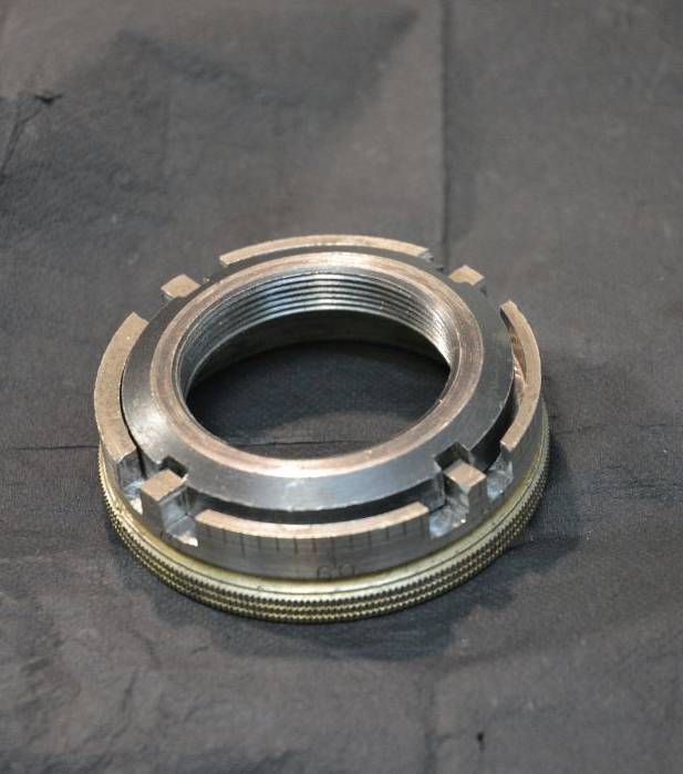
I made a very solid wrench to handle the dish and fit all four of the cut outs in the nuts. The donor steel material all came out of the scrap box. There was a graduated ring from a handwheel off an old lathe, a very solid cup shaped piece from an old lantern style tool holder and a length of wrought iron work for the handle.

I milled the ring to fit the nut and then turned a spigot on the piece from the tool holder to locate inside the ring.

Then the pieces were all welded together to finish the tool.
This wrench works extremely well, there is no tendency to slip off. The rigidity of it combined with the spindle locking tool permits a very fine adjustment of the bearing preload. Prior to the drive modification I used the hook spanner but the nut would always move in jerks due to its flexibility. Then adjusting the bearings was difficult problem.
Good tools make light work of some jobs.
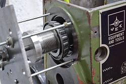
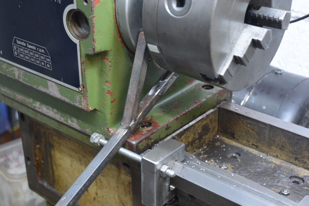
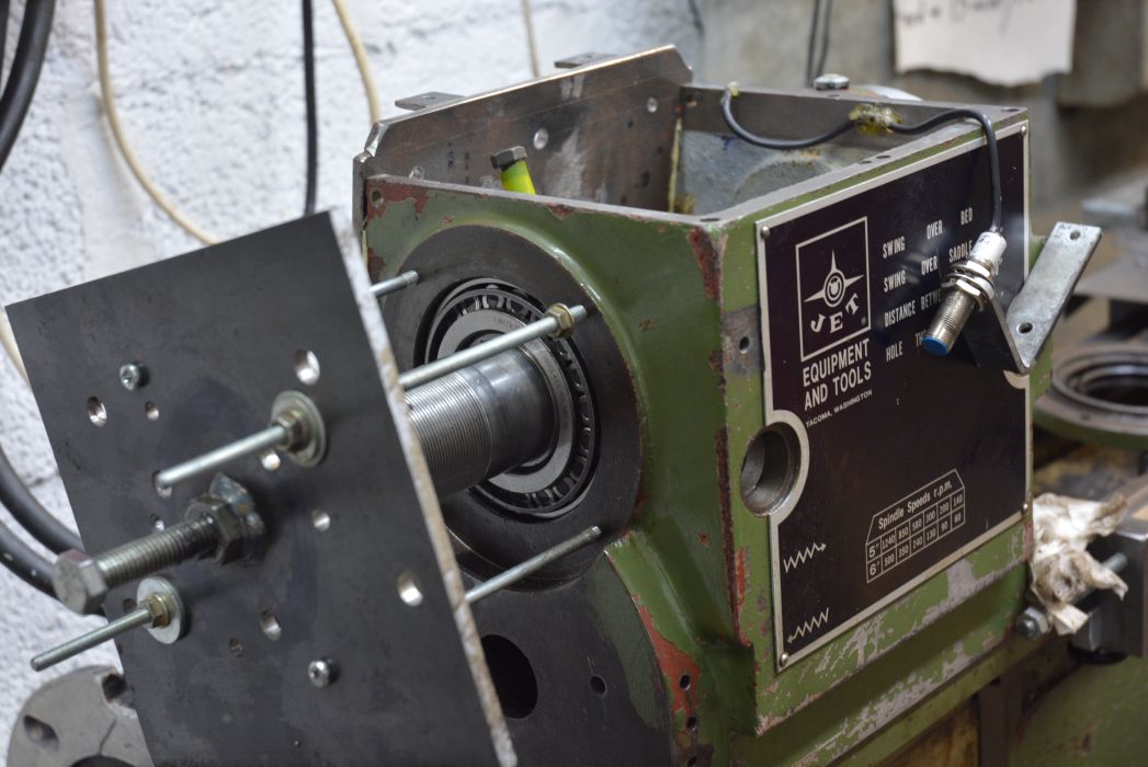
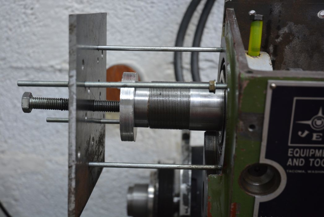
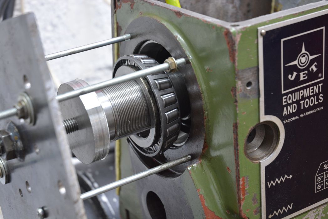
Once the spindle nuts could be removed the spindle needs to be pushed out of the rear bearing to extract it. The spindle and bearings are fitted with interference and so considerable force is necessary to separate them. As before there is no substitute for doing properly with a suitable tool. A heavy mallet is the weapon of choice for many people but is certainly the wrong choice if you have any intentions of reusing the bearings. Heavy impacts will damage the bearings and greatly shorten the time before failure. A smooth force such as you get with an hydraulic or screw puller is much better. The puller than I used is very simple to make. It was made as a puller for separating crankcase halves of some motor cycle engines and had multiple holes to fit various tasks. To use with the lathe I only had to drill 4 more holes and find a couple of long 6 mm bolts and some 6 mm allthread.
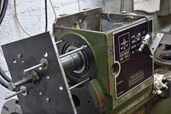
The bolts and all thread were screwed into the 4 holes that normally hold a seal plate, an aluminium plate protected the end of the spindle from the force of the puller screw.
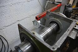
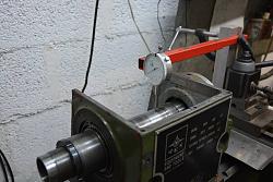
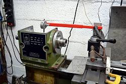
With the spindle extracted and devoid of the internal pulleys etc. I reassembled it to check for alignment. This is normally done by means of a hardened and ground test bar or by test machining and measuring. What better than to do it with the spindle? This requires that the spindle is not bent and is parallel over the measured range. Checks showed that both requirements were fullfilled. My last lathe tool in this post is both simple and crude but rigid enough and effective. I checked and corrected both vertical and horizontal alignment. The following pix show it better than words can.


 Reply With Quote

Bookmarks