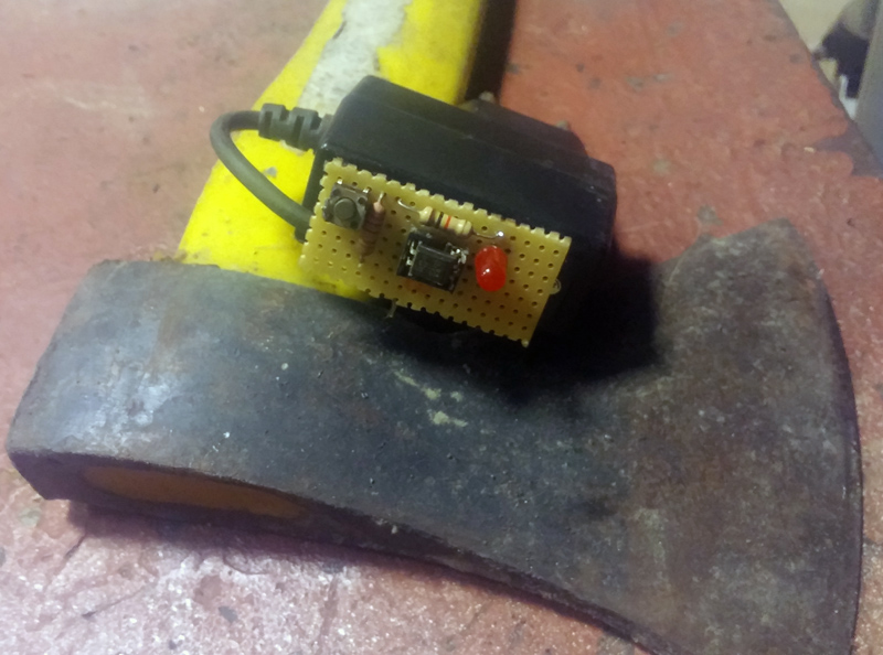
Very simple and useful optocoupler tester.
Printable View
Very simple and useful optocoupler tester.
<!-- BEGIN /var/www/html/homemadetools/protected/modules/zeus/views/tool/postUpdate.php -->
Thanks darkoford! We've added your Optocoupler Tester to our Electronics category,
as well as to your builder page: darkoford's Homemade Tools. Your receipt:
<div id="blocks"> <div class="block b1 pngfix"> <div class="bimg"> <div> <a href="https://www.homemadetools.net/homemade-optocoupler-tester"> <img src="/uploads/226077/homemade-optocoupler-tester.jpeg"/> </a> </div> </div> <div class="head pngfix"></div> <div class="left pngfix"></div> <div class="right pngfix"></div> <div class="blockover b1 pngfix"> <div class="title"> <a href="https://www.homemadetools.net/homemade-optocoupler-tester">Optocoupler Tester</a> <span> by <a href="https://www.homemadetools.net/builder/darkoford">darkoford</a></span> </div> <div class="tags">tags: <a href='https://www.homemadetools.net/tag/tester'>tester</a> </div> </div> </div> </div>
<!-- END /var/www/html/homemadetools/protected/modules/zeus/views/tool/postUpdate.php -->
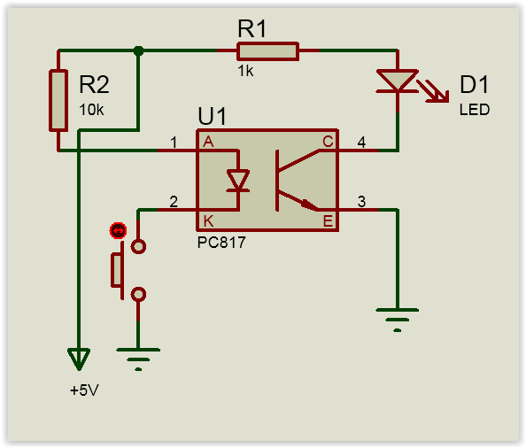
And the momentary push-button goes from Pin 2 to Gnd, right?
Yes Push-Button pin2 (GND) or + 5V.Quote:
Originally Posted by DIYSwede
Added Push Button:
Ok, thanks - but shouldn't the pushbutton only pull current thru the internal LED,
whilst the + feed to R1 is continously on?
How would you otherwise find if the tested coupler's phototransistor is bad, continously on?
Just my 2 cents.
Cheers
Coupler's phototransistor is bad if push button ON -> LED OFF, good if push button ON -> LED ON.
Umm - but that would also be true when the phototransistor is fried ON at all times, wouldn't it?
-Guess you'll have to provide a continous positive feed to R1, (when the LED will be OFF if the coupler's OK)
and the pushbutton only to pull some current thru the optocoupler's LED (turning the D1 ON).
Having the PB to supply everything will not test for a faulty, continously ON phototransistor.
Cheers
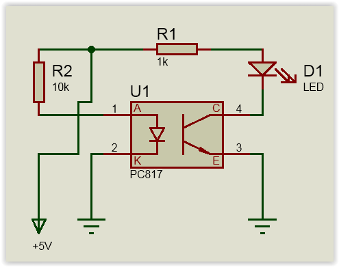
If there is no voltage at the anode and the cathode, the transistor does not connect the LED to ground and the LED does not work.
The voltage at the anode and cathode opens the transistor and connects to earth, allowing voltage and current to flow to the LED.
A transistor is a switch that is open without activating the base.
AFAIK a transistor is a current amplifier, but could also be used as a switch and in this setupQuote:
Originally Posted by darkoford
(including photo-trannies) they have 2 preferred failure modes:
continously open (where in your test circuit the LED won't turn on when button is pushed), and
continously closed, which state your circuit cannot test for, as you let the button power both the
optocoupler's LED as well as its transistor, simultaneously.
Put another way: Your circuit would (incorrectly) pass a bad optocoupler that that's in this second failure mode.
If you, OTOH, power the phototrannie continously, and merely use the momentary PB to turn the internal LED on/ off,
you'll see both eventual failure modes, (as well as its OFF operation)
I personally use test circuits to check for any possible failure mode, hence my previous suggestions.
But then, though real simple to do if needed, they're merely suggestions.
Cheers
It is my fault that I did not record of the defective optocouples.
Cheers
Would you be so kind to provide schematics which is suitable to test both of the failure states you mentioned of an optocoupler?
Thank you.
No big deal, hegefer:
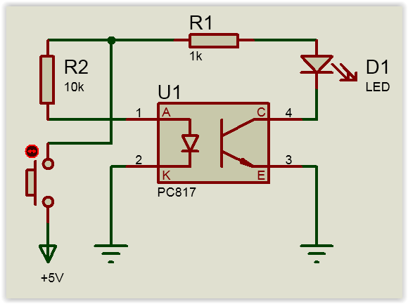
-Just hook the (normally open) push-button between the opto-couplers Pin 2 to ground (instead of as per the schematic).
Then the +voltage will feed the opto-transistor at all times, or rather as long as the +supply is on,
but the button will draw current through the coupler's LED only when pushed.
Thus you check that:
1) The transistor won't lead when the internal LED is off (No push: External LED OFF),
2) That it'll lead when, and only when PB is pushed (Push and hold: LED lights up), and
3) That the transistor also shuts off when PB is released (Release PB: LED goes off,
thus eliminating that no stray, internal current keeps it ON,
an indeed very rare, but still possible fault mode)
2 cents
Dear DIYSwede,
Thank you for your quick and detailed answer.
hegefer
Circuit with ground switch:
Thank you! I am just about to make one. Very useful tester.Quote:
Originally Posted by darkoford
I don't know if there is another way to check. This is easy to do.Quote:
Originally Posted by hegefer
Why one would need another method? It works perfectly!Quote:
Originally Posted by darkoford
Thx
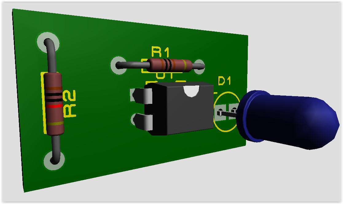
It would be easier if it could be tested directly on PCB. :)