Free 186 More Best Homemade Tools eBook:  
Get 2,000+ tool plans, full site access, and more.

User Tag List

Results 1 to 10 of 10

Thread: Outboard motor for lathe threading? Really? Ideas welcome!

  1. #1
    Supporting Member DIYSwede's Avatar
    Join Date
    May 2019
    Location
    Stockholm, Sweden...
    Posts
    634
    Thanks
    415
    Thanked 799 Times in 319 Posts

    DIYSwede's Tools

    Outboard motor for lathe threading? Really? Ideas welcome!

    Warning: You're approaching wall-of-text area! No vids or ads!

    Disclaimer: To all of you truly inventive minds, I unfortunately have to say that:
    this thread is NOT about hooking up a naval outboard motor to a lathe -
    but merely an additional PMDC worm drive to a lathe's spindle.
    -Sorry for crushing everybody's false hopes - but then, it's someone's sad mission to do that too...

    -Lack of torque in the lo rev range of lathes is a common complaint,
    and having a 7 x 14" chinese assembled kit lathe I'm lazy enough
    NOT to build an add-on back gear assembly or some jack-shaft kludgery in the tight motor compartment.
    Also, not particularly needing to crack the Hi-Lo POM plastic intermediate gear in the headstock either...

    I'm not at all putting these methods down - to each his own,
    I'm just all for the simple, cheap and fast git-it-done, and hence I figured:

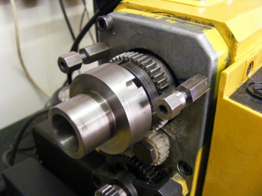
    While soon fixing a threaded spindle spider to the headstock (for stock stick-out support),
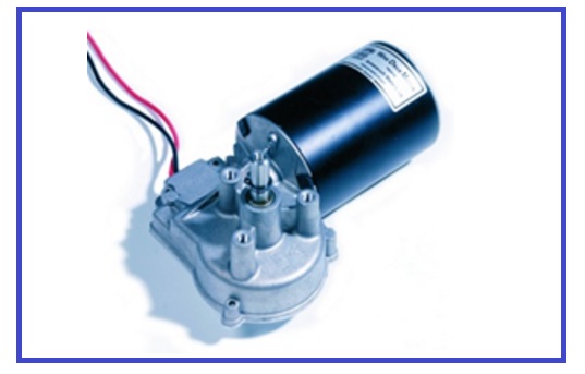
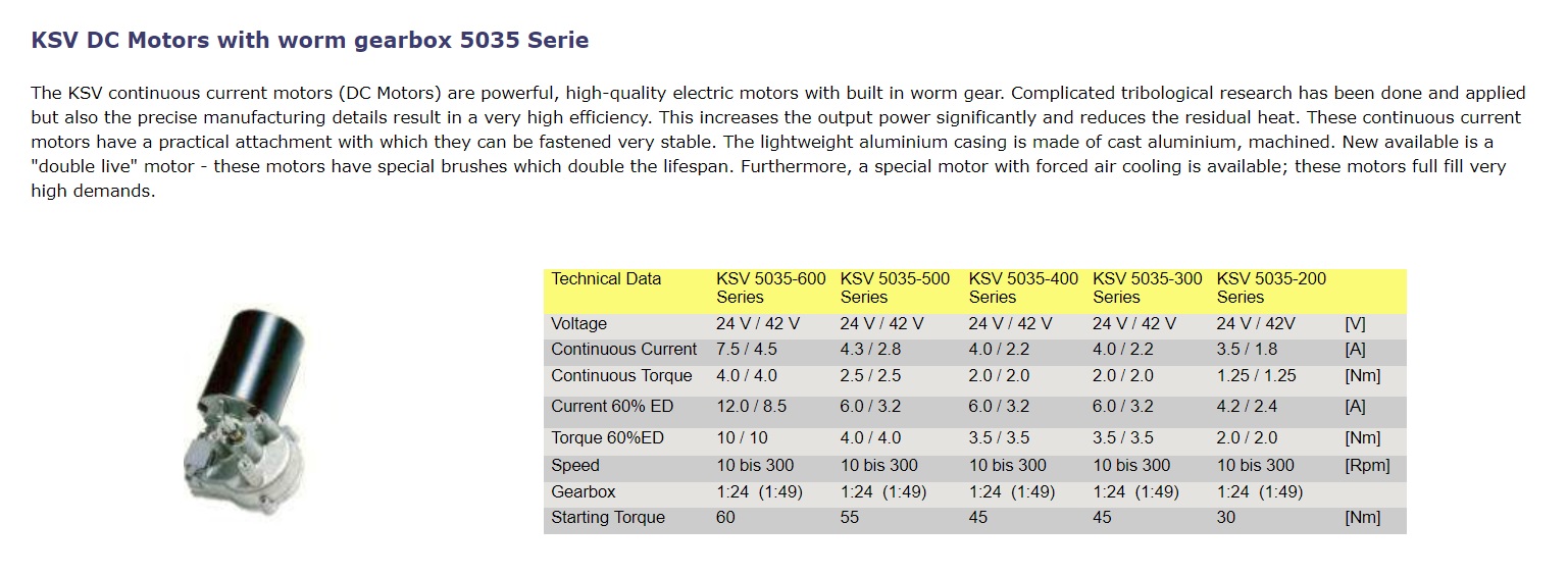
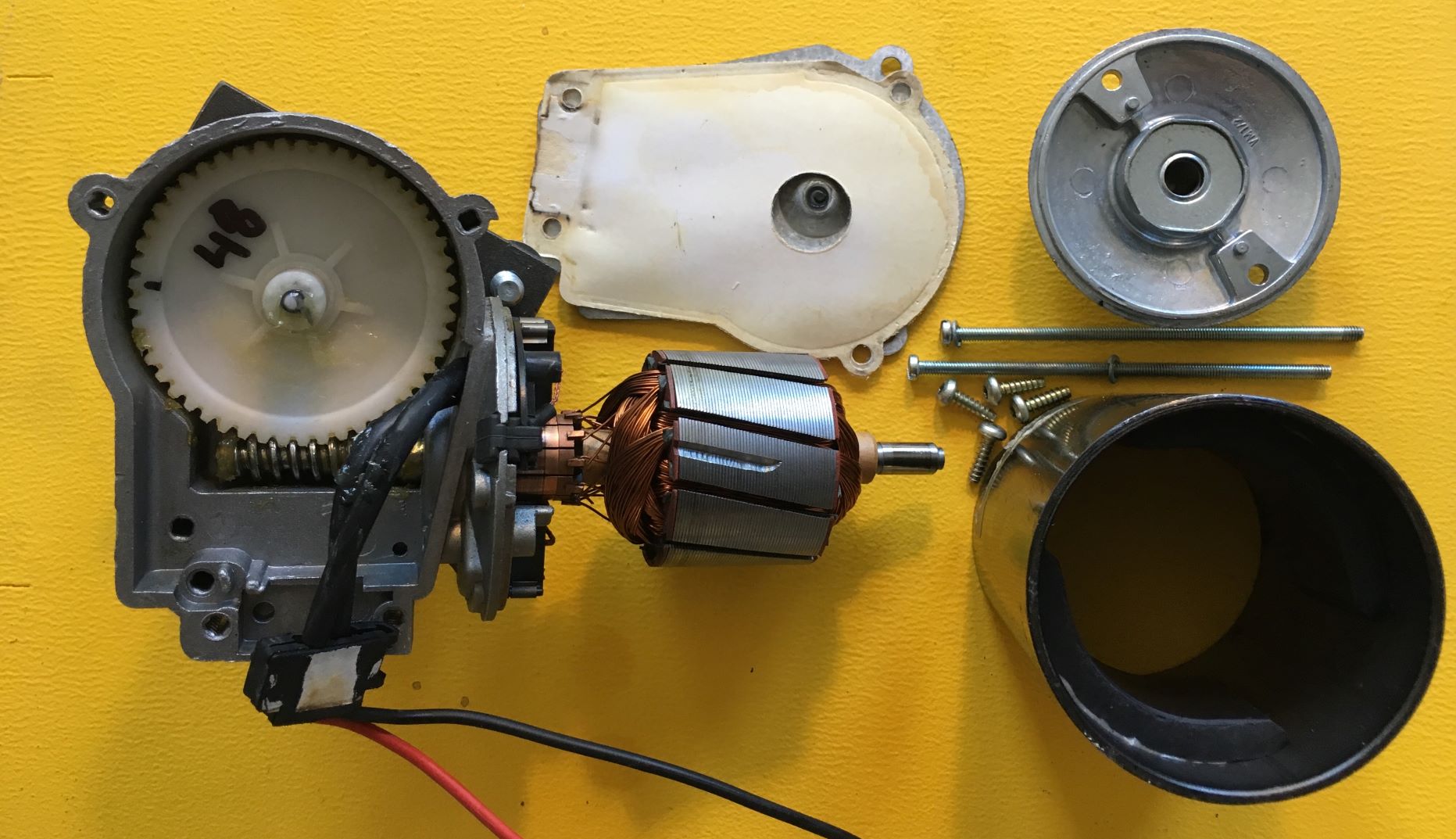
    I thought: -Why not "just add" one of those < 500 W, <75 Nm torque, <200 rpm worm gear PMDC drives lying around?

    Mounting that worm drive rigidly and non-intrusively to the left end of the headstock,
    working thru some dog clutch directly at the spider,
    I could get all the no-hostage torque for threading I'd ever need,
    instead of farting around with my manual handle

    (as I've already found that my winding introduces some to and fro warp to the bed for each turn).

    A side benefit would be that the "pure torque" will then only be applied axially to the spindle,
    and the resulting counterforces would be taken up by the headstock housing directly and entirely,
    NOT by some gear, chain or belt that could bend and offset the spindle axis relative to the bed.

    A 1 kW, 50 VDC max PWM cheap motor control will provide all the juice necessary
    (fed by an E-bike LiPo power pack & charger I got (for FREE!) from a work buddy that had his E-bike stolen).

    I haven't actually seen any project like this tried anywhere on the Interweb,
    so now I share this idea, hoping the collective consciousness of HMT will pitch in!

    Ideas, suggestions for, and problems in this approach most welcome!

    Cheers and TIA, Johan

    186 More Best Homemade Tools eBook
    Last edited by DIYSwede; Jul 25, 2019 at 02:11 AM. Reason: Correcting misleading title

  2. #2
    Supporting Member DIYSwede's Avatar
    Join Date
    May 2019
    Location
    Stockholm, Sweden...
    Posts
    634
    Thanks
    415
    Thanked 799 Times in 319 Posts

    DIYSwede's Tools
    -No vids or ads, but perhaps a few pics and some add'l text will hound all you "reluctant contributors" out?

    Design considerations:
    1) Application of "Pure torque" at the spindle thru a (ex-plumbing brass adapter) spider,
    something like this one, but with a hex end outwards:
    Outboard motor for lathe threading? Really? Ideas welcome!-spindle-spider.jpg
    2) Simple spacer (like the above hex spacers) attachment of KSV 5035, 600 series 48 VDC worm motor
    Outboard motor for lathe threading? Really? Ideas welcome!-ksv-5035.jpg (black motor can dia 90 mm by 100 mm length)
    attached via a plate and torque arm to the headstock end, with a simple hex socket attached to the output axle.
    Outboard motor for lathe threading? Really? Ideas welcome!-ankarsrum-ksv-5035-datasheet.jpg
    3) Electrics: No-nonsense 46 V LiPo (ex-e-bike) battery pack thru a Chinese 1 kW 50 VDC PWM regulator.
    4) Its output relay controlled by an adjustable end stop microswitch attached to the bed,
    providing cutting/ threading close to a shoulder. Reversible drive, with an add'l full speed return pushbutton.

    Assumed achievements:
    1) No side force to the spindle/ headstock (like thru a gear or pulley) as the motor straddles the headstock.
    2) Longevity for the headstock's (disconnected) inner Acetal gear, as the lo rev & high torque only works to the spindle.
    3) Leadscrew and saddle merely "trodding along" at any chosen pitch or module.
    4) Easy non-destructive mounting/ dismantling and hook-up.

    Ideas, suggestions for, and problems in this approach most welcome!

    Cheers
    Johan (soon off for a week at the Adriatic Sea)

    2000 Tool Plans

  3. The Following 2 Users Say Thank You to DIYSwede For This Useful Post:

    olderdan (Jul 23, 2019), Toolmaker51 (Jul 25, 2019)

  4. #3

    Join Date
    Jul 2012
    Location
    Cheshire, UK
    Posts
    14
    Thanks
    1
    Thanked 29 Times in 6 Posts

    drmico60's Tools
    Hej Johan,

    Your ideas are very interesting and I shall be following this development as it progresses.

    My first comment is that you seem to indicate that the motor assembly would be mounted on studs occupying the threaded holes used by the gearbox cover screws. In fact your second picture is I think taken from my website (mikesworkshop.weebly.com).

    Bearing in mind that the motor will have to project further back to proposed hexagonal drive coupling then I doubt whether the studs would be sufficiently strong and rigid to cope with the high torque that would be generated by the motor. I think you would have to bolt the motor onto a substantial bracket that was itself firmly attached to the headstock casting. This should not be too difficult to arrange.

    Enjoy your holiday in the Adriatic and I look forward to catching up with the project when you return.

    I used to work for Swedish Match and lived in Jonkoping for some years.

    Best regards

    Mike

  5. The Following 2 Users Say Thank You to drmico60 For This Useful Post:

    DIYSwede (Jul 25, 2019), olderdan (Jul 23, 2019)

  6. #4
    Supporting Member olderdan's Avatar
    Join Date
    Jun 2016
    Posts
    781
    Thanks
    1,456
    Thanked 1,531 Times in 463 Posts

    olderdan's Tools
    Hi Johan
    Interesting idea which could work and the sort of project I like.
    I am wondering about the worm wheel in the wiper drive as all the ones I have encountered are made of nylon or similar and not expected to cope with the sort of torque you will place on it. Also despite your concerns I would still consider a toothed belt drive, (ideal for slow speeds) and and would give the option for gearing down to reduce the motor loading also easily slipped on when needed and the mandrel pulley could then stay in place without losing the though bore of the lathe mandrel. That motor assy would also make a great independent drive for leadscrews.
    Look forward to your completion.
    Regards
    Olderdan
    Last edited by olderdan; Jul 23, 2019 at 11:18 AM. Reason: further thoughts

  7. The Following User Says Thank You to olderdan For This Useful Post:

    DIYSwede (Jul 25, 2019)

  8. #5
    Supporting Member DIYSwede's Avatar
    Join Date
    May 2019
    Location
    Stockholm, Sweden...
    Posts
    634
    Thanks
    415
    Thanked 799 Times in 319 Posts

    DIYSwede's Tools
    Thanks, Mike and Olderdan for pitching in - and you're absolutely right, Mike - I "borrowed" (w/o asking - pls forgive me)
    the pic from you (and also the very good idea for a lathe ammeter, which I made simpler and cheaper in this post:
    http://www.homemadetools.net/forum/m...addition-73074

    Your page has truly been an inspiration to me thru the last two years -
    and I'm glad you survived the Swedish years in "Småland's Jerusalem" as the town is sometimes called for its many active churches...

    Intermediate plate attachment: In my middle pic of the worm drive, you clearly see the three M6 threaded studs 120 deg apart around the output axle.
    I'm thinking the drive bolted to an 12 mm Al plate with the M6 SHCS recessed in it, and from the other side:
    the 12 mm (gear cover screw) hex studs coming into these plate holes, thus fixing it axially (and laterally).
    Then some longer arm to this Al plate will in its other end be fixed to "a convenient, rigid place for torque relief", so that the studs won't bend or twist.
    This is my "working hypothesis" as of now - recovering in the hotel room from a day out in +32 deg C and the scorching sun in Split, Croatia.

    @Olderdan: You're right regarding the 49:1 plastic wheel. It's the weakest point, especially as the drive also have to work in reverse,
    thus forcing the wheel up against the wimpy tin lid, instead of down against the output end ball bearing.
    Outboard motor for lathe threading? Really? Ideas welcome!-split-5035.jpg
    This will eventually be taken care of thru some serious axial bearing.
    Now - I know I'm privileged enuff to be having at least half a dozen of these KSV 5035 mothers,
    (salvaged from heavy duty office table pillars, a 150 kg load at 2 ips lift verified for a 13 mm 3-start screw in a Delrin block)
    so I've already tried them out in different applications, and have yet to break one:
    Worst case scenario: braked until locked output with 39ish VDC from 3 series coupled SLA batteries.
    No shearing, fraying or other damage noted of the 10 mm thick Delrin gear/key/ axle combo noticed,
    just the ammeter maxing out at >20 A. So I doubt my threading/ worm- & hobcutting in my 7 x 14 will tax the drive harder than that...

    Thanks for sharing your ideas, and I guess this'll be a learning process - in which I'll buy a few setbacks and damage,
    perhaps even finding I was barking up the wrong tree - there might be good reasons for NOT doing what I'm trying?
    I haven't seen anyone trying this - and I don't particularly need being original - I just had the stuff around and thought: -What if...

    Regards, Johan
    Last edited by DIYSwede; Jul 23, 2019 at 03:08 PM. Reason: added pic

  9. #6

    Join Date
    Jul 2012
    Location
    Cheshire, UK
    Posts
    14
    Thanks
    1
    Thanked 29 Times in 6 Posts

    drmico60's Tools
    Hej Johan,
    No problem with you using my website picture.
    Not sure how you intend to fix the hexagonal end to the spindle. If it is screwed on the then there would be potential problems running the motor in reverse. Reversing the motor is often used when threading metric thred on an imperial machine and vice versa. Possibly some sort of locking pin to prevent the hex end unscrewing would solve this.
    Mike

  10. The Following User Says Thank You to drmico60 For This Useful Post:

    DIYSwede (Jul 25, 2019)

  11. #7
    Supporting Member DIYSwede's Avatar
    Join Date
    May 2019
    Location
    Stockholm, Sweden...
    Posts
    634
    Thanks
    415
    Thanked 799 Times in 319 Posts

    DIYSwede's Tools
    "Hej igen", Mike! (We really shouldn't get provincial now, should we? )

    Thanks for your suggestions, which are absolutely relevant in this case,
    as a pure counter-nut probably won't be sufficient.

    It's a pure Amadeal/ Real Bull/ Big Dog CJ18A Metric lathe -
    but I've 3D printed some 63 T gears for cutting "Inferial" threads and hobs,
    (I borrowed Marv Klotz' term, and I'll prove or contest his saying:
    "Why would anyone lucky enough to have a metric lathe want to convert it to cut inferial threads?")
    and I cut in forward & reverse, as well as with the tool upside down at the rear position, behind the job.
    "Hard fun" is my pastime or life-long curse.

    Second reason and use (yet a secret) for this "Slo-rev UltraTork" gadget,
    is also to devise some sort of hob/ mill tooth relieving thingy,
    much less cumbersome to make and use than an Eureka Tool
    (which is rather just intended for mills or gear cutters - not for hobs...).

    Time will tell how well that idea will be realized, look an eventually turn around.
    After all - my saying is "-Quick, dirty, cheap and operational!"
    But 1st things first!

    ATB
    Johan
    Last edited by DIYSwede; Jul 24, 2019 at 06:15 AM. Reason: Terrible line breaks

  12. #8
    Supporting Member Crusty's Avatar
    Join Date
    May 2019
    Location
    Dry Gulch, Tx
    Posts
    749
    Thanks
    220
    Thanked 845 Times in 324 Posts

    Crusty's Tools
    From the title I mentally pictured an Evinrude or Honda connected to a lathe. What a letdown when I discovered the error of my interpretation. Oh well, cooling would have been a nearly insurmountable problem anyway.

    Don't discount toothed belt drives though. One of the reasons that they're seen in so many places is that they handily solve a variety of engineering problems.
    If you can't make it precise make it adjustable.

  13. The Following User Says Thank You to Crusty For This Useful Post:

    DIYSwede (Jul 25, 2019)

  14. #9
    Supporting Member DIYSwede's Avatar
    Join Date
    May 2019
    Location
    Stockholm, Sweden...
    Posts
    634
    Thanks
    415
    Thanked 799 Times in 319 Posts

    DIYSwede's Tools
    Quote Originally Posted by Crusty View Post
    From the title I mentally pictured an Evinrude or Honda connected to a lathe. What a letdown when I discovered the error of my interpretation. Oh well, cooling would have been a nearly insurmountable problem anyway.

    Don't discount toothed belt drives though. One of the reasons that they're seen in so many places is that they handily solve a variety of engineering problems.
    Sorry, Crusty - I was narrowminded enuff not to see the obvious!
    Thanks for reminding me, and I've already put the thread title within quotation marks,
    as well as added a disclaimer paragraph for clarity.

    Thanks for your suggestion - IMHO, toothed belts (discount or not 
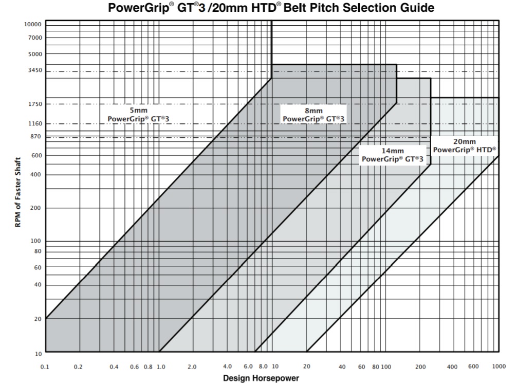
) are great for high power at pretty high revs,
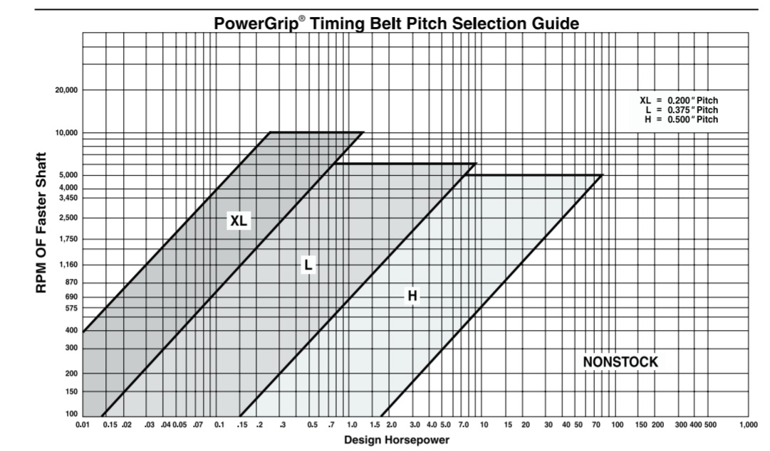
    but as the revs go down problems with transfered force in conventional mini lathe belts arises:

    Outboard motor for lathe threading? Really? Ideas welcome!-powergrip-timing-belt-power.jpg

    Then, this method (though probably sturdy enough) would have to use a 14 or 20 mm HTD belt to take the pull.

    Outboard motor for lathe threading? Really? Ideas welcome!-gates-gt3.jpg

    This goes against my design dogmas of being simple to make and attach, but worse:
    It would be absolutely "Uncheap" at least for me.

    My path will still be "kludging and winging" together what free stuff I've already got - and see what'll happen.

    -Don't hold your breaths, tho - still on vacation for yet another week -
    but today: some R & R from the 3-point landing I took whilst bicycling yesterday-
    (being an addiction personality to the bone) - just "taking a Time Trial bike (i.e. bicycle, Tony!)
    for a spin" on my vacation, I'll abuse that!

    On the up side - now I have a legit reason for staying outta the sea.

    Guess I need an upgrade for my Tetanus resistance too.
    ATB
    Johan
    Last edited by DIYSwede; Jul 25, 2019 at 02:55 AM.

  15. #10
    Supporting Member Crusty's Avatar
    Join Date
    May 2019
    Location
    Dry Gulch, Tx
    Posts
    749
    Thanks
    220
    Thanked 845 Times in 324 Posts

    Crusty's Tools
    Nothing wrong with your wording Swede - in fact it's correct usage.

    I don't think any non-native English speaker is expected to know all the popular vernacular - for that matter Brits and Yanks commonly use terms which are unfamiliar to each other and it's supposedly the same language. I just thought that the image of an outboard boat motor connected to a lathe was funny and not that out of line with things found on this site.


    186 More Best Homemade Tools eBook
    If you can't make it precise make it adjustable.

  16. The Following 2 Users Say Thank You to Crusty For This Useful Post:

    DIYSwede (Jul 25, 2019), Toolmaker51 (Jul 25, 2019)

Thread Information

Users Browsing this Thread

There are currently 1 users browsing this thread. (0 members and 1 guests)

Bookmarks

Posting Permissions

  • You may not post new threads
  • You may not post replies
  • You may not post attachments
  • You may not edit your posts
  •