25 Attachment(s)
Radius turning attachment
Hi All
I made this radius attachment to assist in the manufacture of dies for the ever ongoing bead roller project I started. I had a shopping list that I wanted the tool to meet.
1; a radius attachment that would be able to produce both internal and external radius
2; must fit a standard tool-post holder so the top slide could stay in position.
3; Tool setting the required radius.
4; Adjustable stops to control the angle the tool could be rotated.
I had previously made a radius attachment from a cheap Chinese boring head led on its side which was compact but difficult to set and I felt was limited in it uses. So a new one was needed. I did use some of the parts from this tool and modified to suit the new, hopefully improved radius attachment.
I had an idea in my head (very dangerous I hear you all say :confused: ). So with the blue prints in my head off to may scrap box to see if I could find some material to suit the design. Luckily I did have all the materials to hand and set off making the tool which was completed in three days.
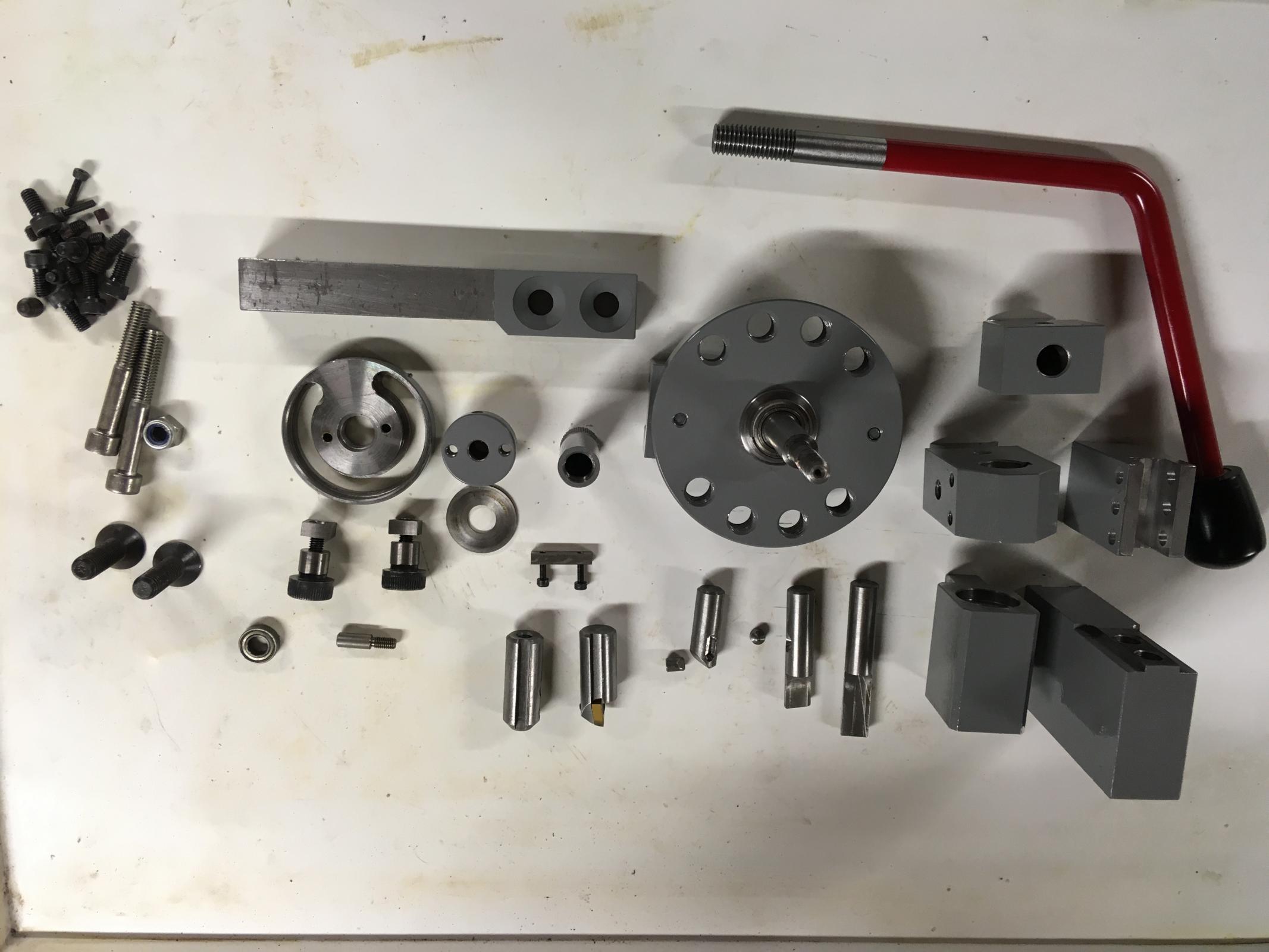
The photos below show the finished components and the assembly.
Attachment 31877
All components finished and painted ready for assembly.
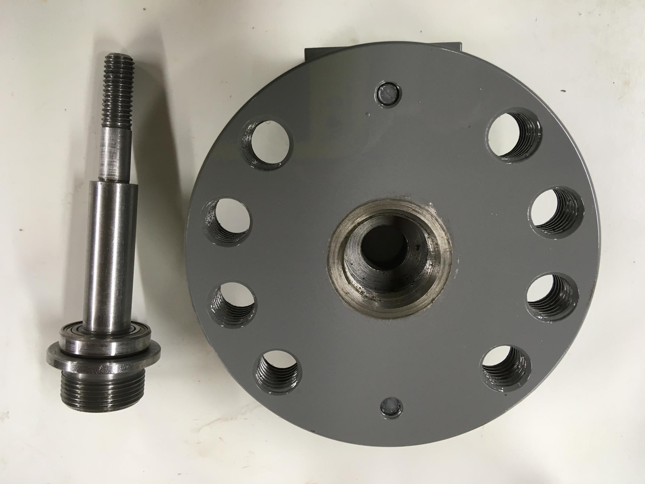
Attachment 31856
Main shaft and base plate
Attachment 31857
Main shaft fitted to two bearings in modified body from old tool
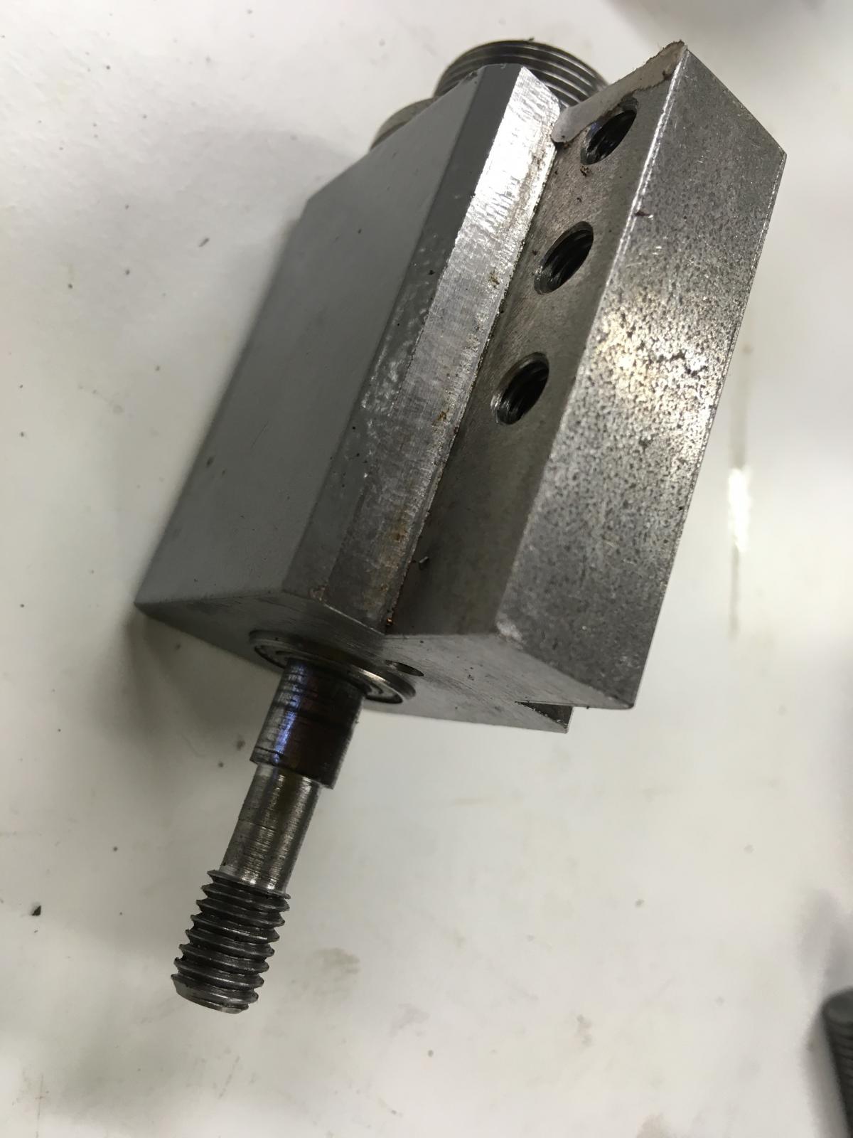
Attachment 31858
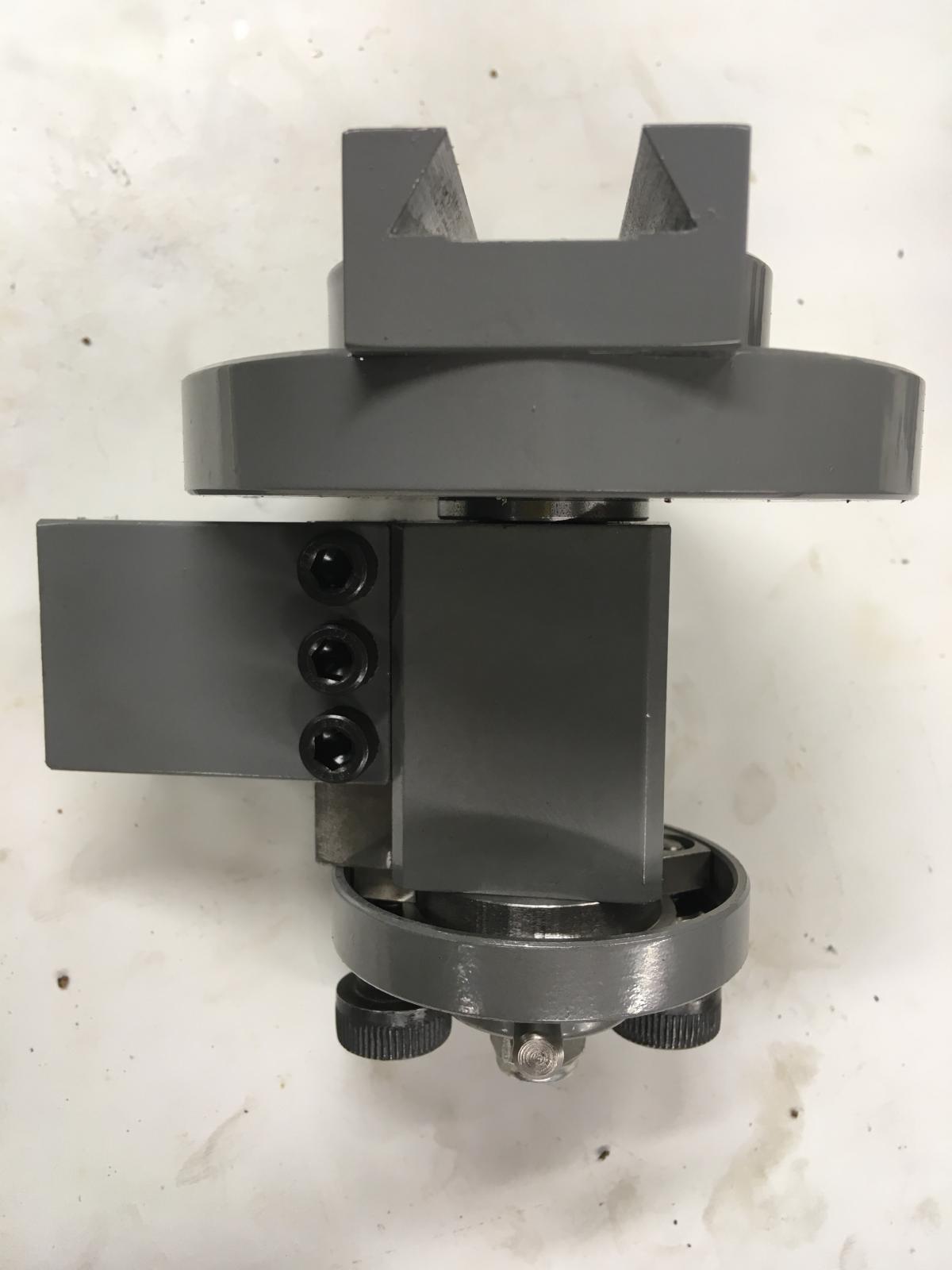
Main body and shaft held in place with adjustable rotation stops assembly. The stops are shoulder bolts and move in a slot and clamped hand tight to desired position. There is a stop bar attached to the main shaft which can move between the stop positions.
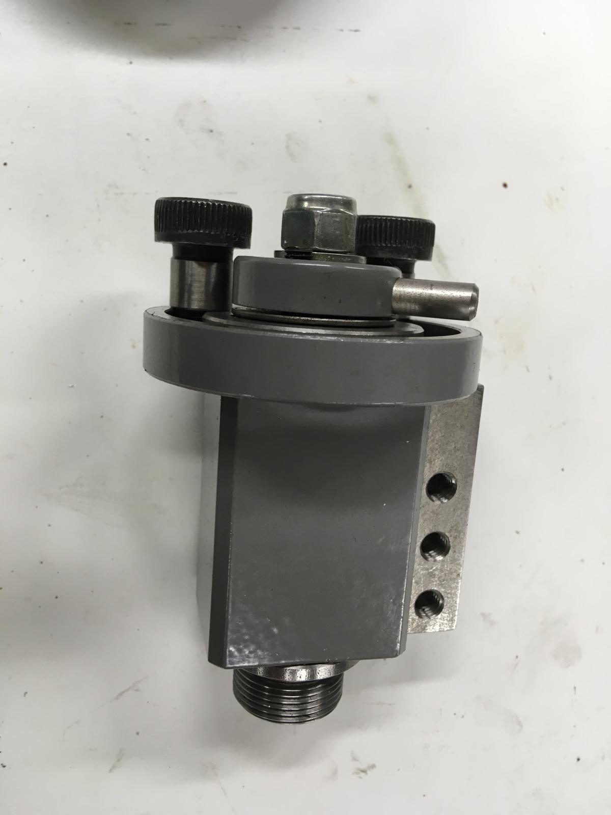
Attachment 31859
main body and base plate
Attachment 31878
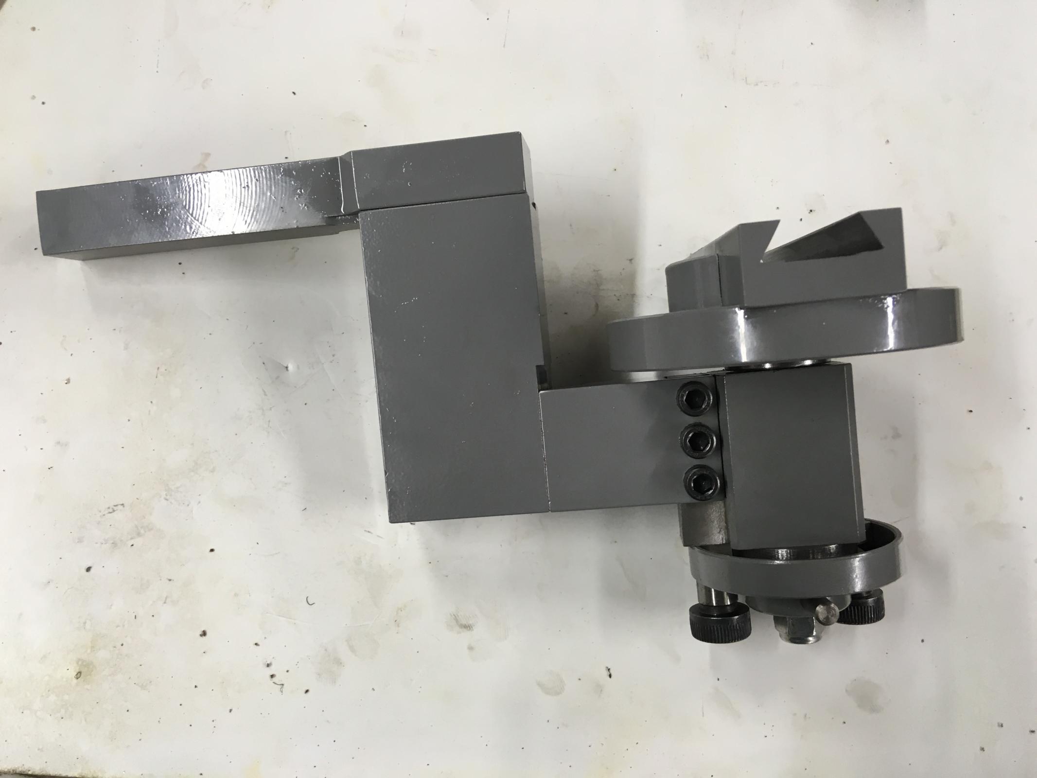
Tool post shank bolted in place
Attachment 31861 Attachment 31880
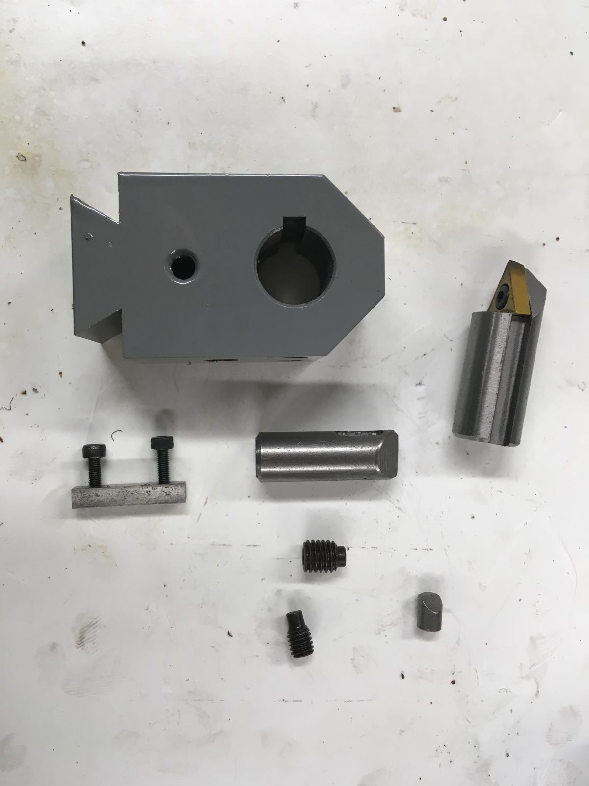
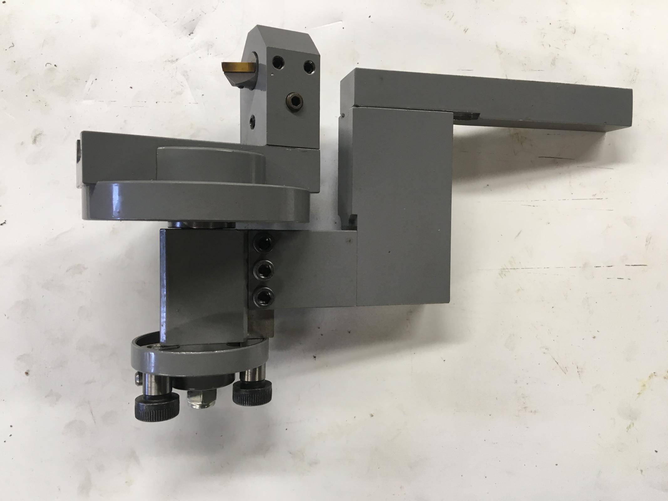
Radius attachment tool holder components. Tool holder in place
Attachment 31863 Attachment 31873
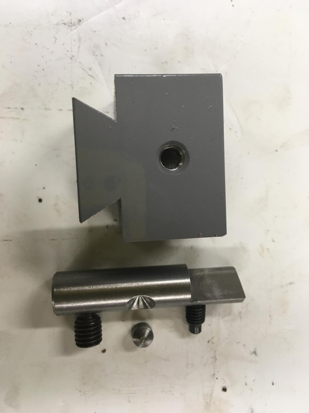
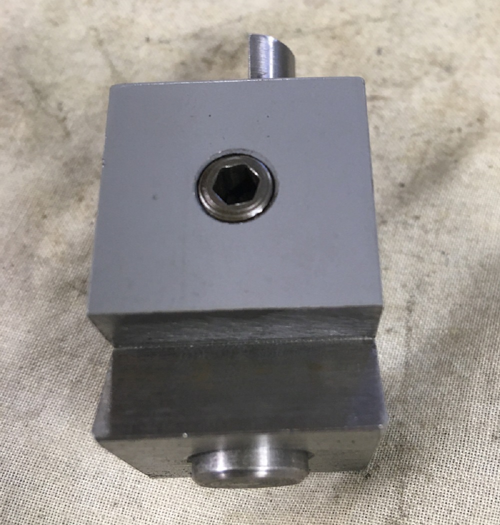
Internal radius setting jig components.
The setting gauge shaft also works as a locking pin to hold the assembly in position when setting. A grub-screw when tightened pushes the small taper pin in to the counter sink which moves the shaft down to lock in the base of the dovetail. This also enabled me to maintain the correct orientation of the shaft, so the flat face can be clamped square to the cutting tool. A slip-gauge can then be placed between both setting gauges to set correct radius from centre pivot point. Once set both the slip gauge and centre gauge are removed, leaving the clamped block in place the cutting tool is then simply moved to touch the setting gauge shaft and locked in position. Once set the setting gauge block is also removed.
Attachment 31874 Attachment 31875 Attachment 31876
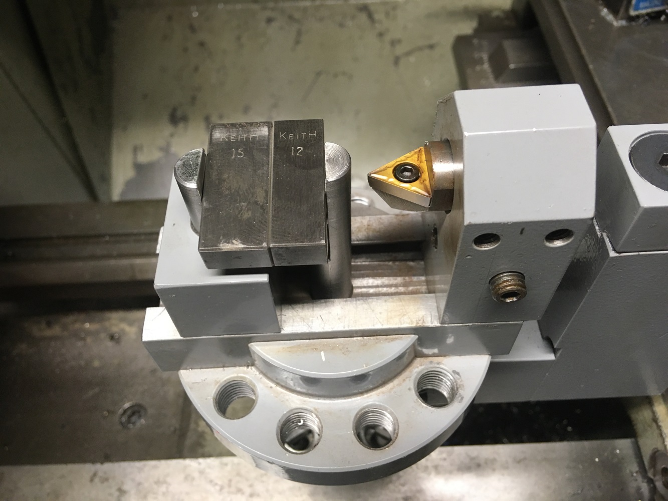
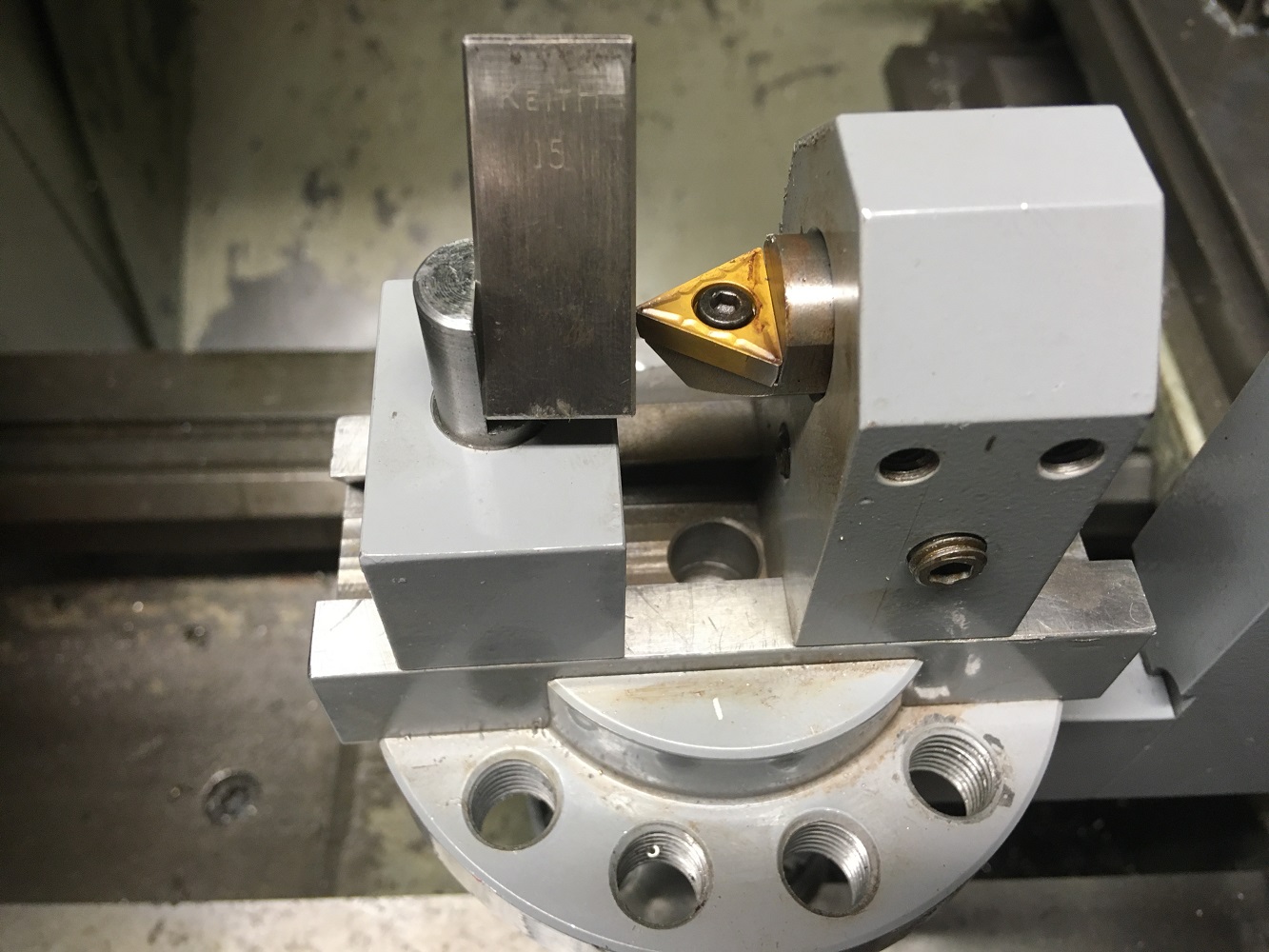
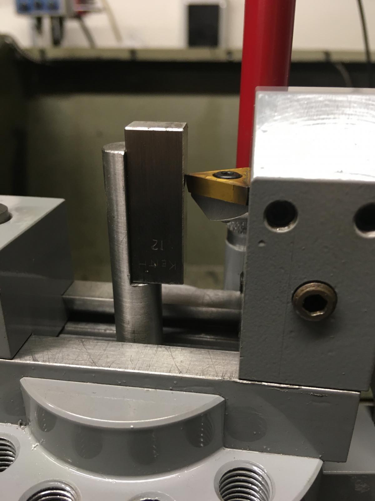
Setting an internal radius using both setting gauges and slip-gauges to cut 12mm radius.
Attachment 31867
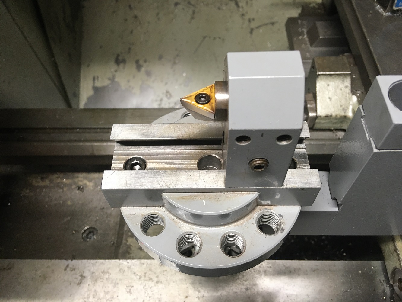
Setting an external radius using only the centre setting gauge and slip-gauge.
Attachment 31864 Attachment 31865
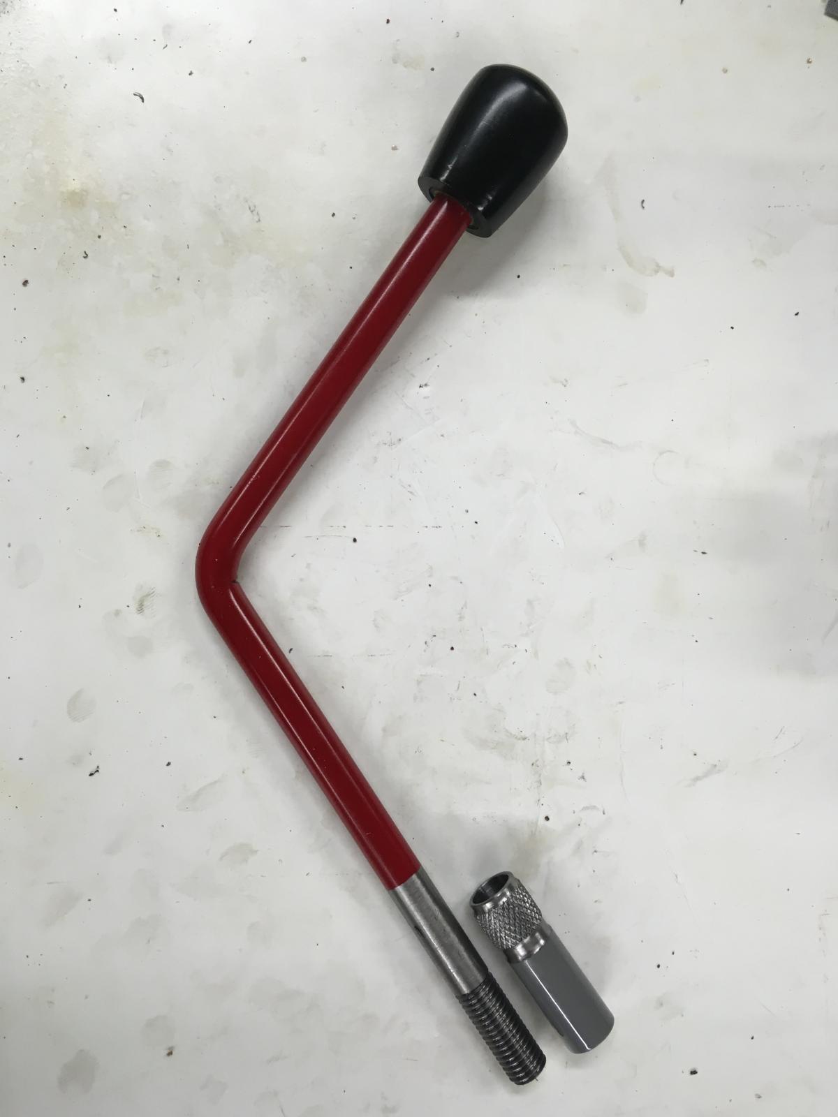
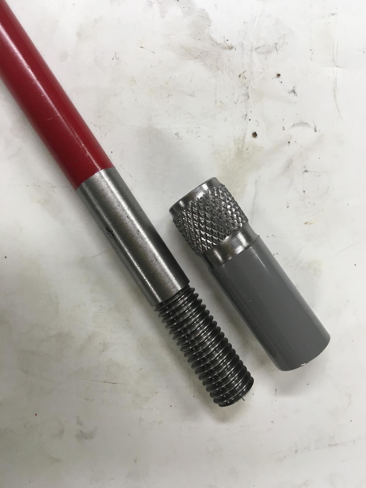
Operating handle and locking collar to ensure the handle can be locked in the correct orientation
Attachment 31879
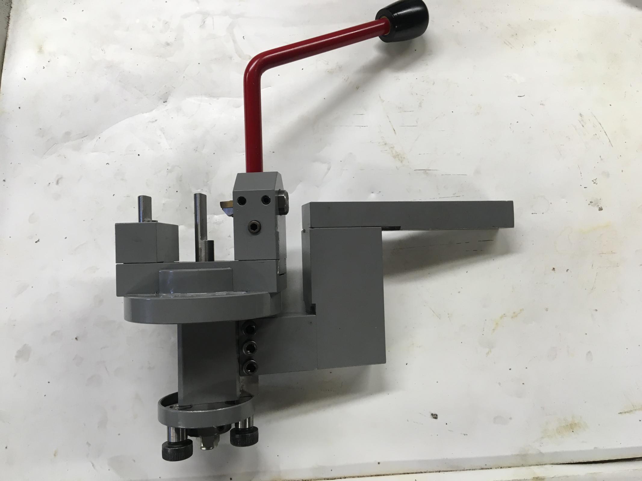
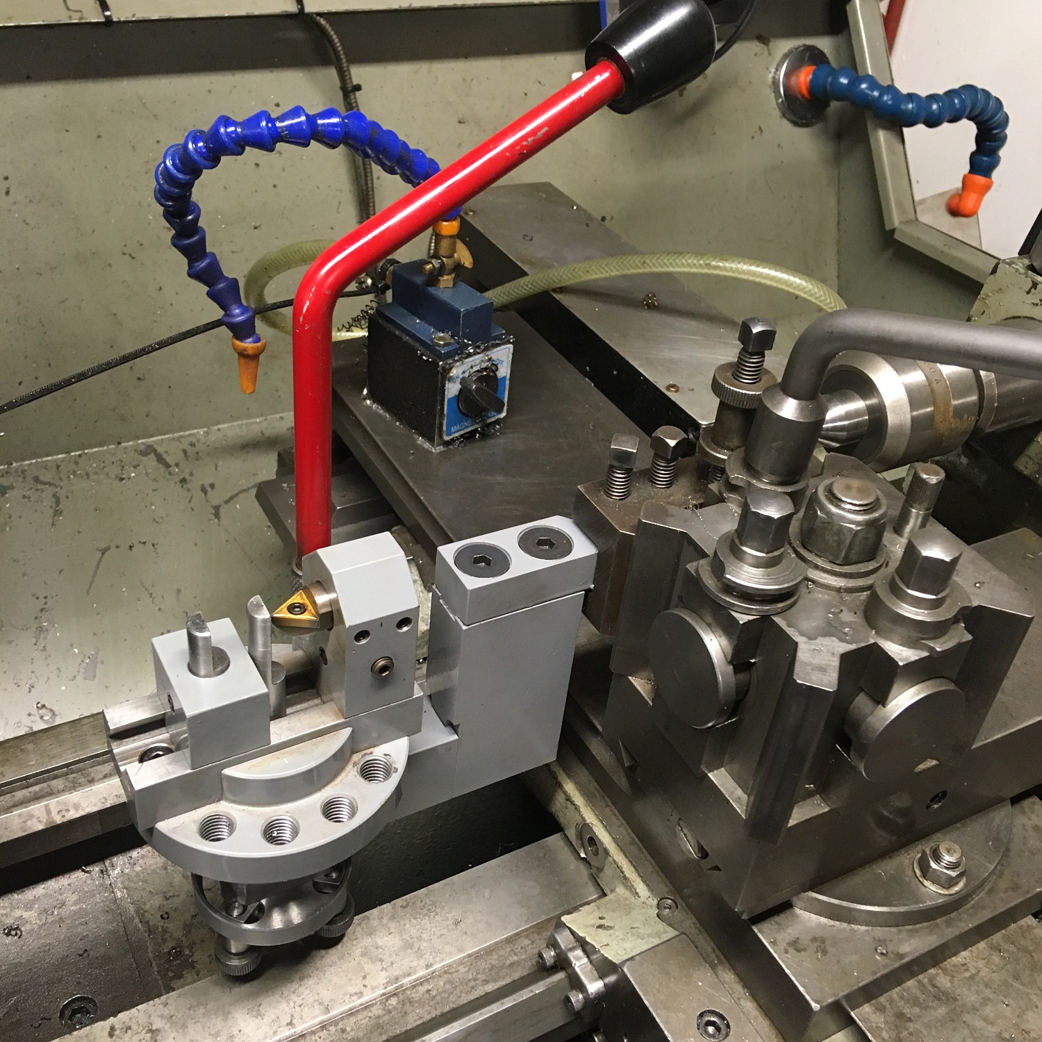
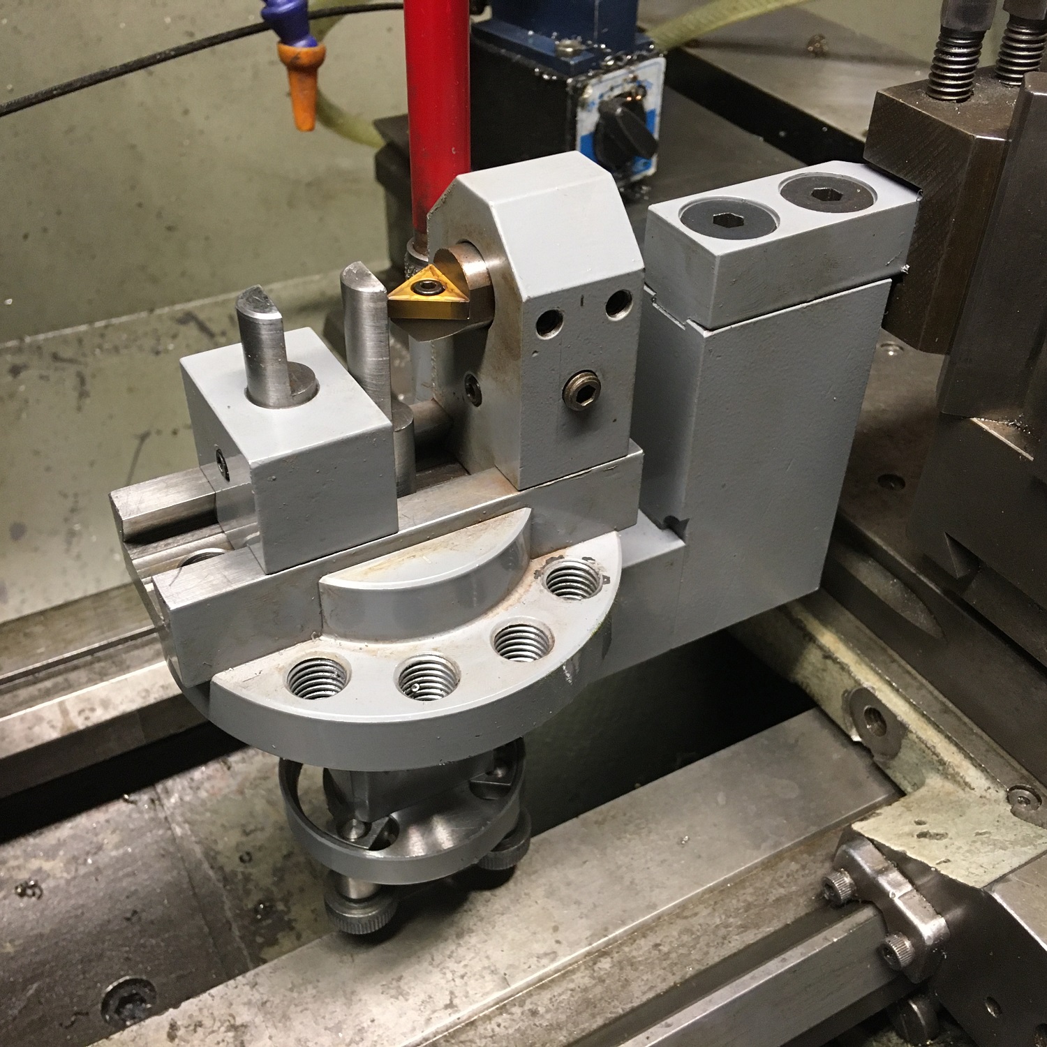
Completed tool with both internal and external setting tools in place. once radius is set they are removed
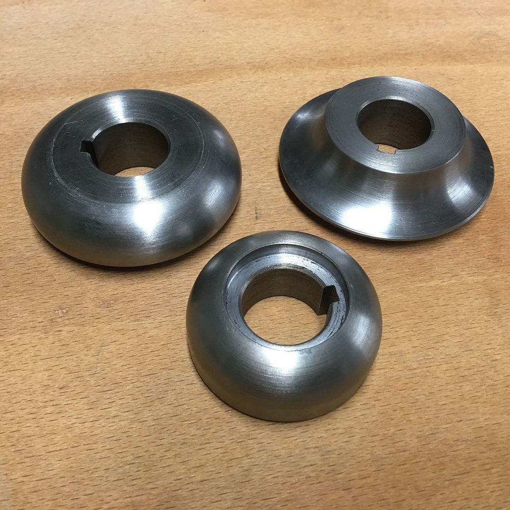
Attachment 31868 Attachment 31869 Attachment 31870
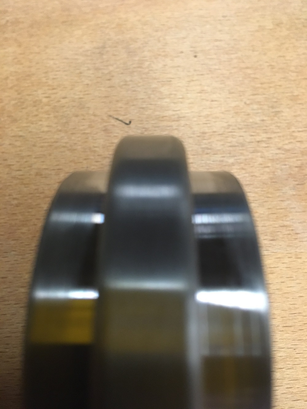
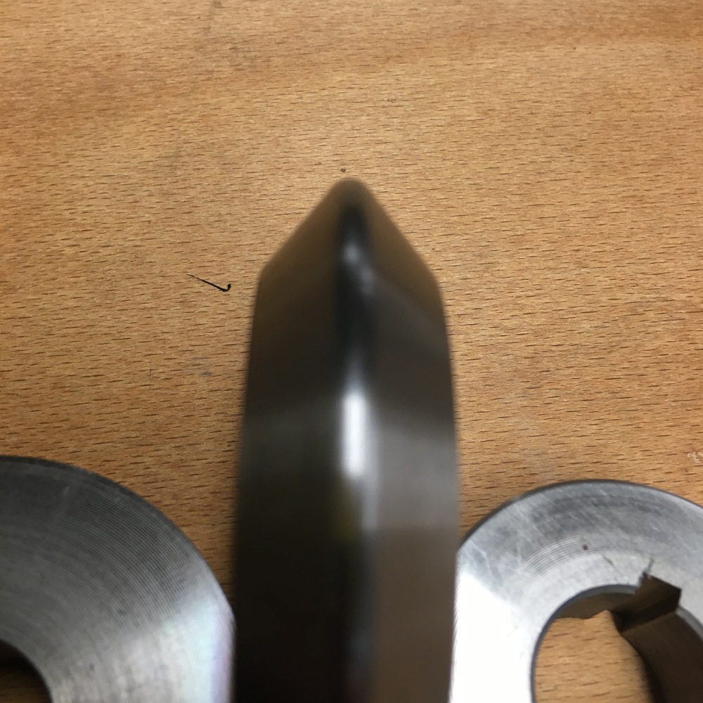
Examples of radius's machined will tool
Attachment 31871 Attachment 31872
Tool held in tool-post with both internal and external setting gauges in place.
Thank you for viewing
The Home Engineer