-
Raising hinges
I know that there are very genius people here, my gate needs rising hinges instead of two gates the idea is to make only one gate but behind the gate there is a ramp. In the net there are some and once i saw one that was made with the ball joins from tractors but there were amy plans or measures to make one. Has anyone here has made one?
Thanks in advance
-
Any more details? A drawing or picture of where this gate goes?
-
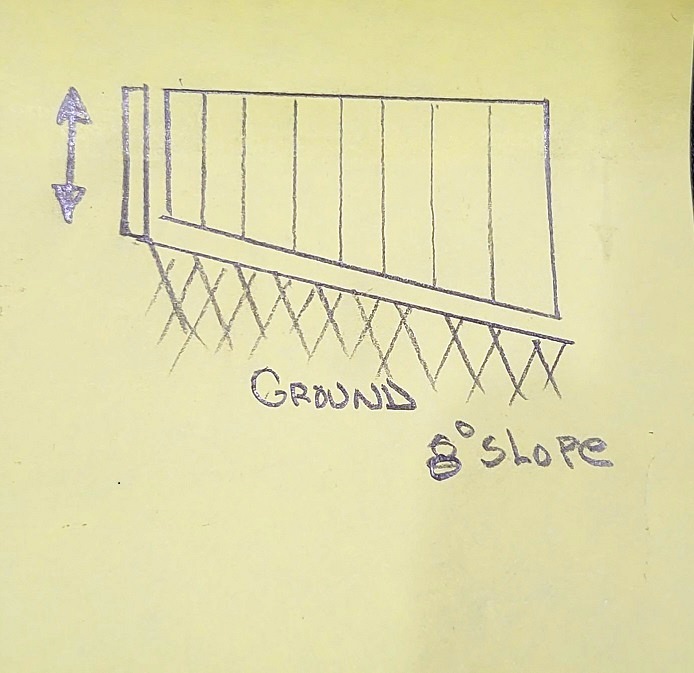
Thank you Buffalo John for your interest to help, n another words behind the gate it is not level it has an inclination of eight degrees. If you want to open the gate it will not open all the way these hinges are offset to give the inclination the gate needs from the inclination of the floor. i hope that I am making myself understandable.
-
Let me see if I am able to make an explanation understood. it has been a long time since I had to make a gate go up hill when opened and I may make things more confusing than they need be. .
Start with looking straight down from the top of the hinged and opposite posts draw a line from the center of 1 post to the other. Assume this to be the centerline of the thickness of the gate. in its closed position. now draw a line from the center point of the hinged post perpendicular to the closed gate center line. These will be our beginning reference points next make a circle centered on the top of the hinged post a couple inches larger than the diameter of the post it makes no difference if the post is round or square at this point but a square post would have an inscribed diameter or a circumscribed diameter inscribed would be the radius from the center to the center of one of the flat sides as a circumscribed diameter would be the radius from the center to one of the corners. just to explain where we stand.
Once you have determined the diameter of your circle this will be the reference for the distance to the center of axis for the top hinge later we will make our debarkation point of the axis for the top hinge lower down on the post positioned as high or a low as you want to have the top of your hinge located down from the top of the gate.
Now the fun part comes. I would normally design my hinges for a gate such as this to be behind the post by locating the centers at a 45°ange between the open and closed position. so we will try this method for now you can alter it to suit your desires. So what we are going to do is make an imaginary point on the circle we had drawn around the top of the post. and draw a line from the center of the posts through that point allowing it to extend outwards a few inches.
We are done with the top view for now we will name this our top plane, but will return later. Now draw a vertical line extending down from the center axis of the top plane to where the bottom plane will be to represent the height of the post we are going to create a view of the opened gate I am going to name this the right plane is could just as well be the left plane depending on whether you are opening the gate away from you hinged on the right or the left. Now that we have established the planes exitance. we want to draw an imaginary line from the circumference of the top circle down to the bottom as well remember this is the axis point of the distance the top of the top hinge will be placed form the post. Next draw a line the distance from the base of the posts to where you want the top of the top hinge to be located .Next start as the base of the post and draw a line to the left at the suspected angle of the inclination for simplicity we are going to use your stated 8° for anyone else needing to make a similar gate their angles may be different. Now that we have established the base line of the slope up from the post with the gate in the opened position we need to draw a line down from the hinge axis top to the inclined line this line must be perpendicular to the line that is drawn at 8° Next we will need to draw the hinge axis line down from the top hinge axis point to the base at 4° from the post this line should be equidistant between the centerline of the post and the previous line, Next we are going to draw a line at the height of the bottom of the lowest gate hinge from the center of the post horizontally to the line that is drawn at 4° and make note of the length this will be the radius from the center of the post to the center axis of the bottom hinge. We are now almost done about all we have to do at this point is if you are planning on using the common gate strap hinges all you have to do is screw them in at the heights you want them at 4° angle from the post at halfway between full open and full closed the centers of their axis matching the 4°line On the gate when it is closed the strap hinges will need to be bent the top one will be short and the bottom one a little longer, When the gate opens it will not remain straight up vertical but will lean some the reason for placing the hinges in the positions I have laid out is to compensate for the angle of the incline in the open position while allowing the gat to be straight up and look like a normal gate.
since the hinges are not mounted at 90° to the closed position but at about halfway between you may find some adjustment to the length of the bottom one stickinig out from the gate and the post may be necessary to achieve the result you need for instance you may have to set the center of axis of the hinges at 5°instead of 4 or if you place them further around to the back of the post you may be able to go slightly less with the angle but much longer on the lengths that the center axis of the hinges are from the gate.
I hope this helps and if not too confusing will steer you towards making your gate function as required.
-
2 Attachment(s)
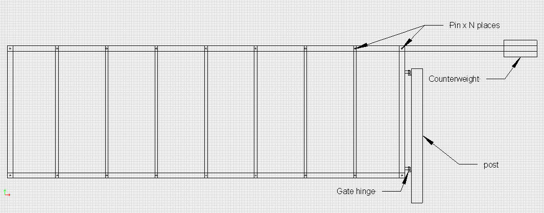
Not knowing what you are keeping in or out...
Here is a fairly simple gate design:
Attachment 42695
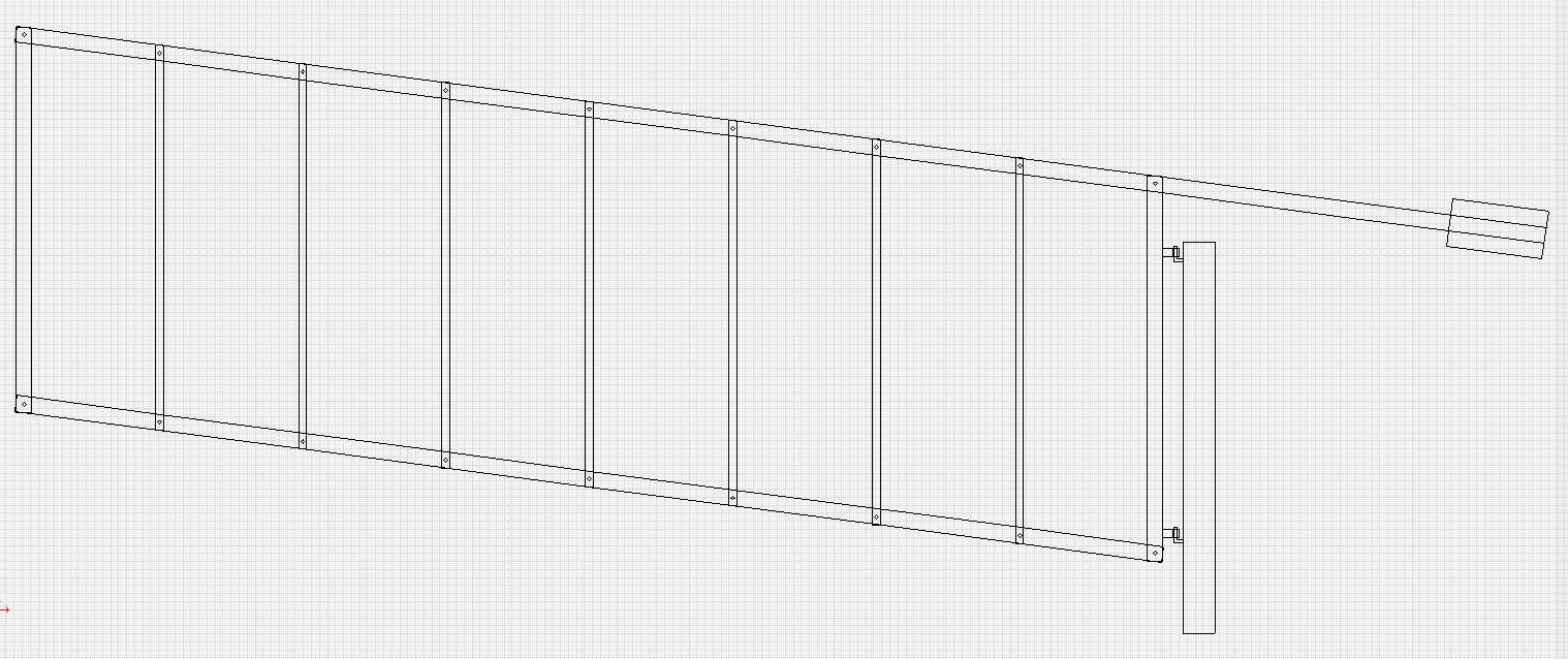
Then when you push down on the counterweight, it raises like this:
Attachment 42696
That angle is 7.5 degrees. There are pins to let the gate swing about the post. You can make the pins be parallel to the opening or at an angle if you want the gate to move more out of the way.
I did it as a 12' gate 4' high - just to get the perspective correct for the drawing.
The rest of the solution is left to the student...
-
1 Attachment(s)
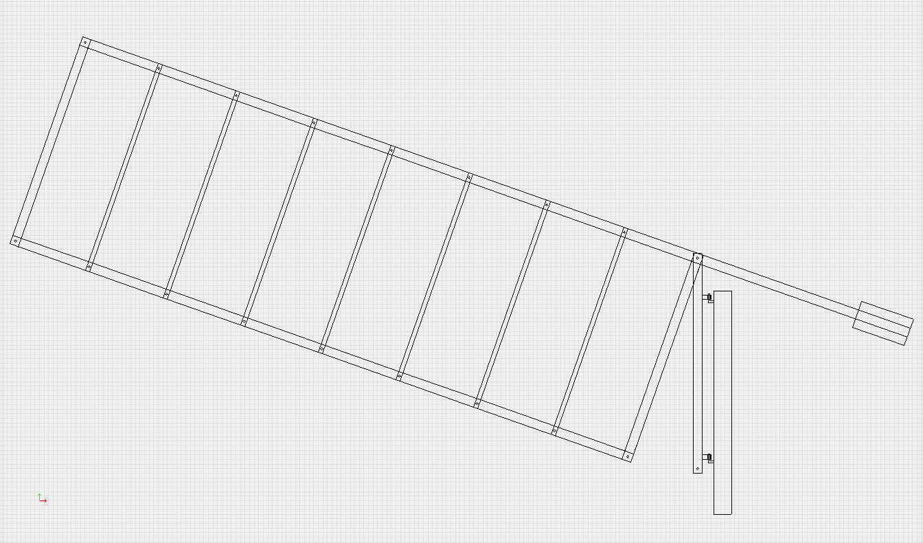
Oh, and making it raise up as you turn the gate is a BIG stress at the hinge pins - a BOAT LOAD of friction.
Again, not know what is kept in or out, the gate will weigh in at 50# to 200# plus the counterweight.
If you want the gate to be rigid so you can use wire mesh, you could do this:
Attachment 42697
-
When looking at a problem like this it is an idea to start with basic dimensions as in width of gate and lift of gate needed, what the gate is made of and its mass. How is it hung or more importantly what is it hung from as the best solution may be very simple or may require some thought.
-
I've done this before by just offsetting the vertical axis of the pins. Both to make it rise as it opens to clear a slope, and one way I used to make a gate self closing without need for an additional mechanism. If you have a 5* rise, kick the pins 5*, but you'll need a way to hold it open when desired.
-
3 Attachment(s)
I believe he wants to keep the top level as it rotates. In this scenario the long edge of the gate will hit the ground upon rotation. Perhaps a cam-like (or ramp like) action would lift the gate keeping everything level.
Attachment 42744
Baddog, do you mean angle the hinges 8 degrees from the vertical axis?
____________________________
Edit: I found a couple of pics. The caming action I mentioned and offset pin idea posted by Baddog.
Attachment 42746Attachment 42745
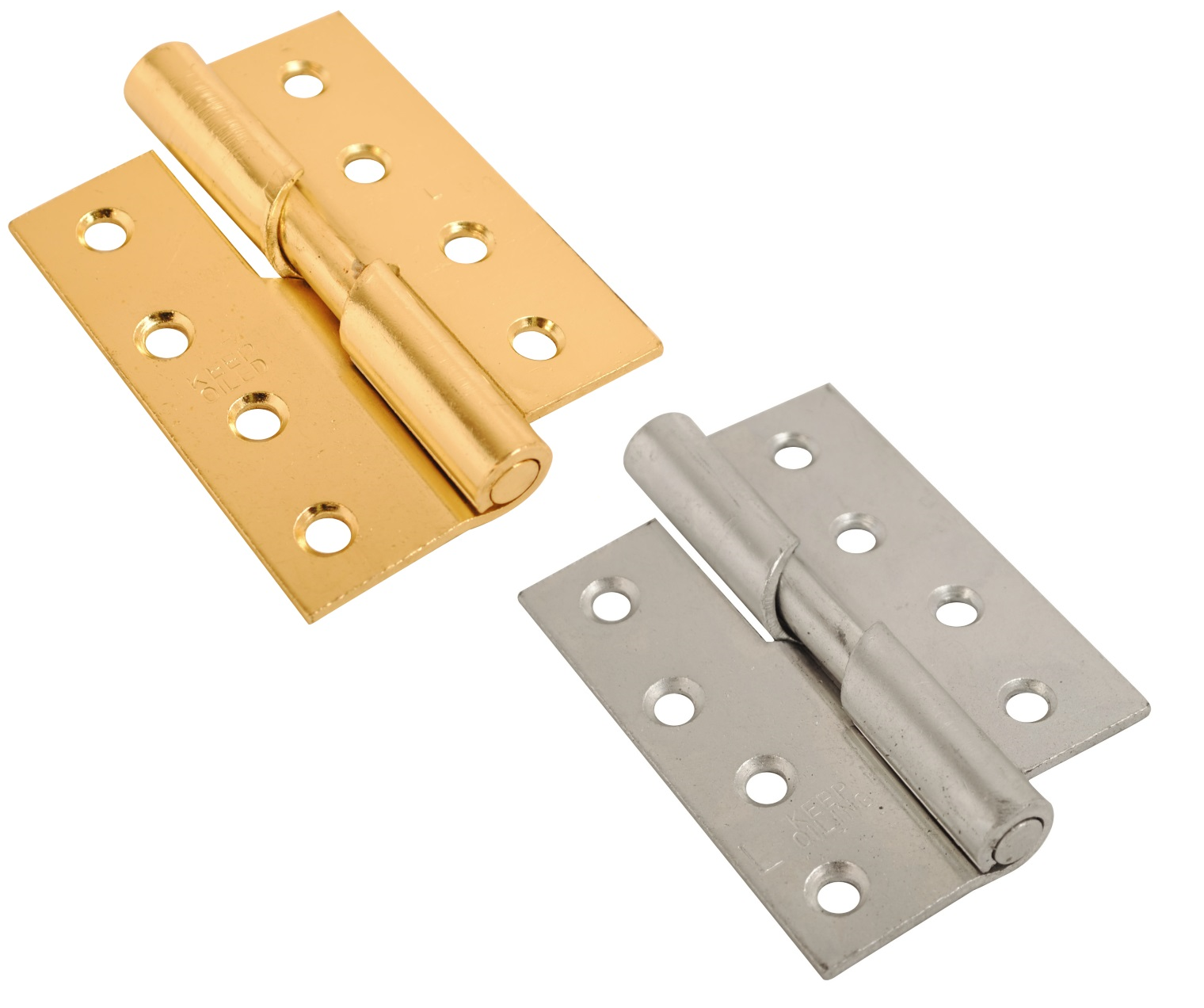
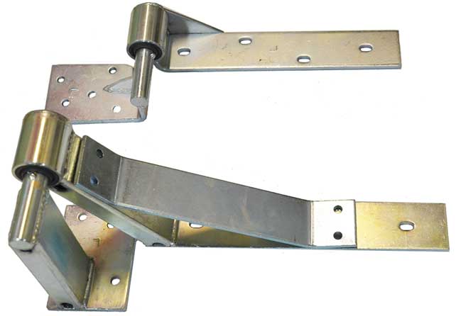
-
Those hinges show 2 ways I've achieved that. The first style is only for small amounts of rise, and uses the ramp to encourage closing. But mainly it just allows the door to be closer to the ground when closed, and only works well when clean. More for a door than gate, certainly not a big gate. The one I did that on was a man gate, was much heavier than that, and only the bottom had the ramp.
The second is what I was talking about. But you have to offset the axis, not just the pins. Both pens remain on the single axis of rotation. The gate is a relatively rigid rectangle, so if you have the hinge axis kicked N degrees as shown, then when the gate is in line with the axis kick out, the bottom of the gate will have N angle to the ground.
But you may need to put a control system of some sort on the gate. I did one like that at my old house for a pretty heavy steel man gate, and it shut like the gates of hell if released from about 45*, but could be easily parked with minimal restraint at ~90*
-
Baddog, could you make a sketch a picture is worth a thousand words. The gate is made of square pipe with the wall of 3millimiters and wit sheet metal it is heavy and 2.50 meters wide by 2.00 meters.
There s a gap below the gate oy 40 mm, what I did was to put a straight bar along the lenght of the gate with a level on top of the it then pivot the the bar the same radius or arc the gate will make then measure how much lift it was needed to clear the ground it is 20 millimeter.
-
Salt fever provided the image 2 posts before your last post.
Ideally you want the hinge pins on the same axis. So, imagine the pins are a single rod 2 meters long. Normally, that would be vertical making the gate swing horizontally. But you apparently need a 20mm rise when the gate is 90* to closed on one side (down on the other). If I didn't make a mistake, you only need to kick the bottom of the rod out 0.5*, which would be around 17 mm toward the up hill side. Note that's the "rod", which effectively assumes the top and bottom hinge are at the top and bottom of the 2 meter height, so likely needs tweaking depending on actual hinge location.
-
Thank you everybody for your help. My idea is to put a ball join at the end of the bottom hinge when the gate opens it pivots.