
 LinkBack URL
 About LinkBacks


[tech talk below]
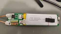
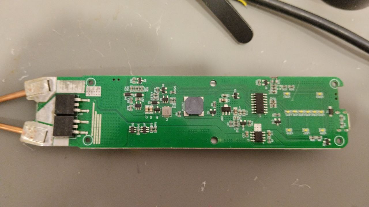
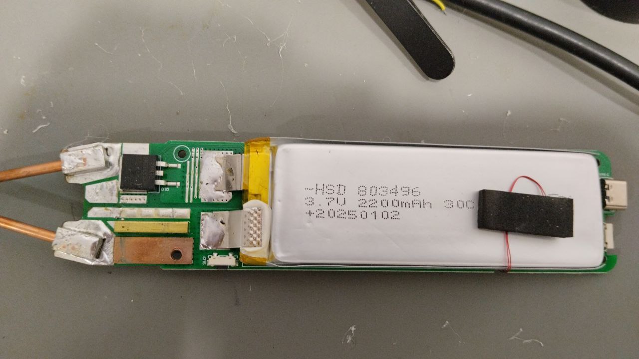
Thinking about this some more, I went and looked at the PCB. I suspect there isn't any standard DW01 on this. This has 3 big FETs to switch the battery to the welding probe. A protection chip would need some sort of FET in series with the battery. To completely disconnect the battery, that would be 3 more big FETs with associated losses across them, probably unacceptable in cost, board space, and functionality of the welder.
Now, a good engineer would have either had the DW01 disconnect the power to the processor and associated circuitry or at the very least have the processor kill power to the switching regulator and other stuff on the board. Then go into deep sleep until 5V from the USB wakes it back up. It would still have the problem of the battery eventually dropping below the BOD point keeping the processor from waking on USB plug-in. That, too, can be dealt with but I think this might be a bit deep in battery control for whoever designed this. Still, overall it's not bad... just have to keep it charged.
They did, amazingly, put the 5.1k resistors on the USB-C socket. It's rare to see that.
Pictures of the welder below.

 Reply With Quote

Bookmarks