Free 186 More Best Homemade Tools eBook:  
Get 2,000+ tool plans, full site access, and more.

User Tag List

Page 1 of 2 1 2 LastLast
Results 1 to 10 of 15

Thread: Remote control milling machine and lathe help

  1. #1

    Join Date
    Sep 2016
    Posts
    7
    Thanks
    0
    Thanked 3 Times in 2 Posts

    Remote control milling machine and lathe help

    This is my first post and it is a good one. I am a Marine EOD tech and we use a very expensive and poorly built remote controlled 3-in-1 lathe mill for the disassembly and exploitation of ordnance. We can't get parts anymore so we have decided to build our own machine and scale it down some. We have a Grizzly bench-top mill and a Grizzly 9" lathe as our base.

    My goal is to attach motors to all axis with a 50' pendant so that we can mill, drill, and turn remotely but also still use the manual controls of the machine for making tools and parts. I know what a stepper motor and pulse generator are and that is where my experience ends. Any help or advice on how to built the electrical control system is greatly appreciated. Mounting the motors will be the easiest part.

    186 More Best Homemade Tools eBook

  2. The Following 2 Users Say Thank You to eodcoduto For This Useful Post:

    Jon (Oct 6, 2017), Seedtick (Oct 6, 2017)

  3. #2
    Supporting Member Moby Duck's Avatar
    Join Date
    Jan 2016
    Posts
    388
    Thanks
    1,221
    Thanked 197 Times in 124 Posts

    Moby Duck's Tools
    With due respect here, if you are doing work like this, get the Marines to buy you whatever you need. They owe it to you, and should be providing you with the very best of whatever you need. If this ordnance is stable enough to be moved and mounted in a lathe or milling machine, why do you not just take it outside and destroy it? I am not sure what you mean by "exploitation" of ordnance, please enlighten me.

    2000 Tool Plans

  4. #3

    Join Date
    Sep 2016
    Posts
    7
    Thanks
    0
    Thanked 3 Times in 2 Posts
    Quote Originally Posted by Moby Duck View Post
    With due respect here, if you are doing work like this, get the Marines to buy you whatever you need. They owe it to you, and should be providing you with the very best of whatever you need. If this ordnance is stable enough to be moved and mounted in a lathe or milling machine, why do you not just take it outside and destroy it? I am not sure what you mean by "exploitation" of ordnance, please enlighten me.
    Yes we should have the best gear but we don't, most of the time our gear is great but this one fell through the cracks. The DOD is really pushing to have the warfighter start developing and fixing our own gear and not have to lean on industry as much which is awesome, we just purchased a Luzbot Taz 6 and are making training aids with it now!

    For the ordnance part, we are taking measurements and seeing how things work. Our current machine has Yako drivers, motors, and a rotary pulse generator for the z, x, y, and a axis. I would like to adapt this style of system to our Grizzly machines if possible.

  5. #4
    Supporting Member tonyfoale's Avatar
    Join Date
    Nov 2016
    Location
    Spain
    Posts
    1,566
    Thanks
    689
    Thanked 2,646 Times in 709 Posts

    tonyfoale's Tools
    If you just want to use it in manual mode, as against programmed CNC style control, but at a safe distance then this is quite an easy thing to do.
    Physically on the remote you need to decide whether you want to use one pulse encoder per axis or switch a single encoder to which axis you want. Personally I much prefer the idea of one encoder for each axis, this is more intuitive because it mimics the manual controls on the machine.
    Then you need to process the signals from the encoders and convert them into suitable output for the steppers. All that you need is readily available in whatever budget range you have available. Most can be done with user friendly microprocessor boards like the Arduino and Pi. I have done very similar things to your requirements with an Arduino Mega, although without the danger aspect of your task.
    The Arduino Mega can be used directly with the encoders to decipher the signals but I prefer to use dedicated quadrature chips between the encoders and the Arduino. This is more reliable and simplifies the programme coding.
    There a number of off the shelf stepper driver boards which can be driven by the Arduino and drive the steppers, it is just a question of getting a driver board which has the capacity to match your steppers.
    Connecting all that up is pretty simple but then you have to write some code to tell the Arduino how to react, that is probably a stumbling block for many people but this is a pretty simple application and I am sure that you will have people around you who could handle both the connecting up and the programming.
    I'll try to remember to look up the spec of the quadrature decoder chips that I use. There are different types and some are much more suitable than others for this task.
    https://store.arduino.cc/arduino-mega-2560-rev3

  6. #5
    Supporting Member tonyfoale's Avatar
    Join Date
    Nov 2016
    Location
    Spain
    Posts
    1,566
    Thanks
    689
    Thanked 2,646 Times in 709 Posts

    tonyfoale's Tools
    I should have mentioned that you can also hook up numeric displays, LCD or LED, if you want to view the commanded axis positions.
    There is a ton of info on the net about driving steppers with Arduinos and coding examples.
    If you went down my suggested route of using decoder chips I could post the code for reading from those as well as a circuit diag.

  7. #6
    Jon
    Jon is online now Jon has agreed the Seller's Terms of Service
    Administrator
    Supporting Member
    Jon's Avatar
    Join Date
    Jan 2012
    Location
    Colorado, USA
    Posts
    25,559
    Thanks
    7,954
    Thanked 38,837 Times in 11,335 Posts
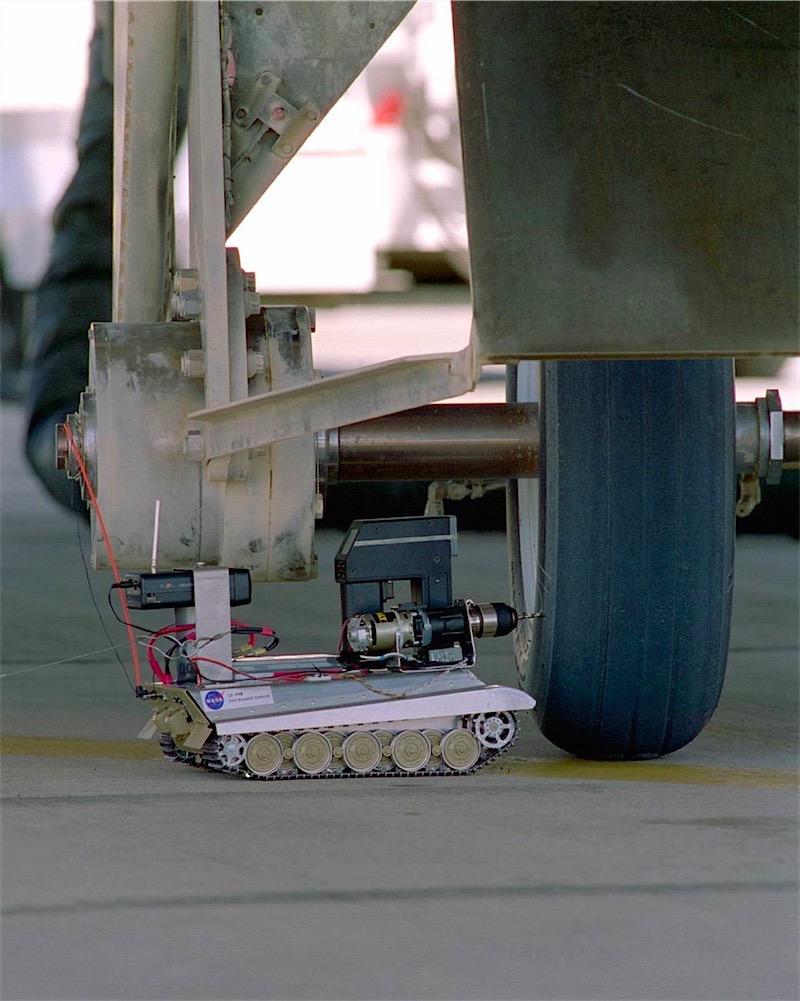
    I'm wondering if NASA's Tire Assault Vehicle might be able to give you some ideas here. They simply mounted the guts of a DeWalt hand drill to a WWII tank model, to safely puncture test-worn tires from a distance. Very similar concept, but of course their application is much lighter:


  8. #7

    Join Date
    Feb 2016
    Posts
    4
    Thanks
    0
    Thanked 1 Time in 1 Post
    My post is about how to do it properly.

    Use ac brushless servos, of 750W, directly coupled to each wheel or screw. 10.000 counts/turn, more or less.

    Option 1.
    Use a CSMIO-IP-S controller, and mach3 cnc sw in manual mode.
    Use an import MPG to control the axis wheels.
    Wire the servo-enable signals to switches.
    This allows full manual use.
    Especially when the servo motors are mounted behind the lathe, it is identical to manual use.

    The csmio uses differential signals, and these can be used for long wiring.
    Other single-ended signals cannot.
    The mpg handwheel has a 3 meter cable. You do not want to extend it too much, due to induced emi electrical noise.
    Have the controller somewhat near the handwheel.

    The csmio has 1 ms response.
    Almost nothing else does.
    It runs at 4 Mhz.
    The csmio is perfectly stable and reliable- and has a 1 ms cutout on losing connection.
    Nothing else does- as far as I know.
    The csmio connects via ethernet.
    Ethernet is always galvanically isolated.
    You could use shielded cable - FTP - and I would urge you to do so.

    I would also very much urge you to make or have made a special screenset for the sw, preventing any commands and automation from being used.

    Option 2.
    Use PLCs, and signal logic, and line drivers, and hard-wired MPGs.
    Same servos.
    This is a better option.
    It will be more complex, harder to do, more custom, and much harder to maintain.
    More expensive, due to lots of work hours.

    3.
    Both options require extensive docs to be written due to the type of work done.
    Both options will be expensive.
    Do not attempt this without sufficient authority and budget. Really, Do Not.

    For example, servos (and steppers) do get induced noise from any signals, and can move unpredictably .. unless earthed.
    If earthed, this *never* happens.
    Earth from multiple points to the powerline gnd.

    I would estimate 2000 work hours, and 5-6k in hw costs.
    It is NOT hard to do.
    But it is very laborious, and extensive tests/proofs are required for any automated machinery that can kill people.
    Likewise, typically, two-stage or double interlocks are usually a legal requirement.

    Only a major grade officer could authorise bypassing such requirements ..
    and usually such as base commander would prefer to authorise supplemental budgets from something else rather than sign bypass orders.

    For example, I could make such a system 3-4-6 ways, in my sleep.
    Unless paid for docs and testing, and guaranteed liability waiver, I would not do such a job for say 30k in pay.
    I could make it *work* in 3-5 days.
    But I would only do the work if I had the 2000 hours to document/test/prove it properly.
    There are endless gotchas and corner cases.
    It is NOT hard to do- as such.
    But a cynical attitude like any automation sales, will-fail vs. may-fail expectations, inducing noise on signals/servos/controllers etc. in tests is probably a good idea.

    The automation *can* be done for 1000$ technically.
    Request orders in writing, request appeal to high command, request review by any competent automation specialist - could be a free consult and likely would be. Imho.

  9. #8

    Join Date
    Sep 2016
    Posts
    7
    Thanks
    0
    Thanked 3 Times in 2 Posts
    A lot to read and process, and if it can be done for under $2000 we are in business. I will start making a shopping list and let everyone know how it is going.

  10. #9
    Supporting Member
    Join Date
    Jan 2017
    Location
    Delta, BC, Canada
    Posts
    4
    Thanks
    3
    Thanked 1 Time in 1 Post
    Sorry, I am of no help. I am an old school machinist with no remote or cnc background.
    Dada

  11. #10

    Join Date
    Sep 2016
    Posts
    7
    Thanks
    0
    Thanked 3 Times in 2 Posts
    Quote Originally Posted by Dada View Post
    Sorry, I am of no help. I am an old school machinist with no remote or cnc background.
    Dada
    I'm an aspiring new school machinist with old school gear, a 1967 Clausing Colchester 13x36 Mk1.5 lathe and a 1976 Bridgeport variable speed mill. I have been on the lathe all weekend and learning is always occurring!

Thread Information

Users Browsing this Thread

There are currently 1 users browsing this thread. (0 members and 1 guests)

Bookmarks

Posting Permissions

  • You may not post new threads
  • You may not post replies
  • You may not post attachments
  • You may not edit your posts
  •