
Originally Posted by
Moby Duck

If you have had the lathe since 2004 and have never used the adaptor, and rarely turn anything between centres, and are unlikely to buy a set of collets for a lathe of this size, then I think that you are going to a lot of trouble for nothing.
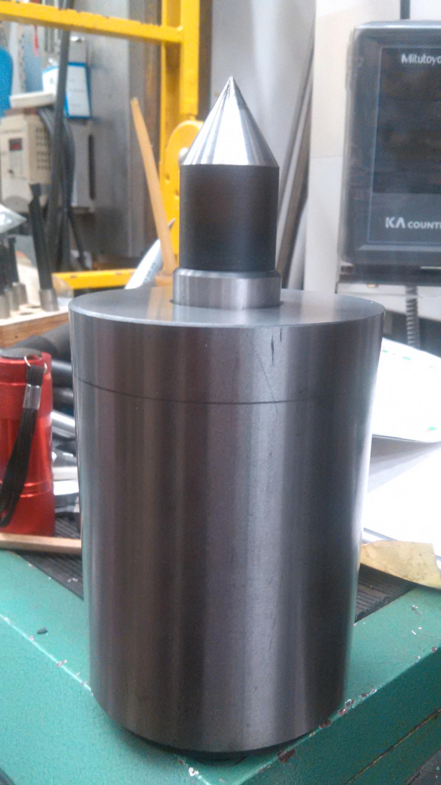
Just take an appropriate sized piece of round steel bar, hold it with a 3 jaw chuck and turn a centre point end on it using the compound. It doesn't need fancy grinding, or even hardening, and it will run exactly concentric with the spindle, and it will remain so until removed from the chuck. In another 12 years when you might need to use it again, simply remount in any chuck and skim and true the centre point.
p.s. I am not a toolmaker but the above has always worked well for me. Precision is nice but not always necessary, and I certainly wouldn't expect to get it from a big cheap lathe.

 LinkBack URL
 About LinkBacks


 Reply With Quote


 You can easily set the compound slide to the desired taper like this:
1- "Pin It")


Bookmarks