
 LinkBack URL
 About LinkBacks


Well as documented else where on this forum I tackled the sloppy Tailstock problem and started adding the Tailstock DRO (the barrel markings were very faint and Imperial only ) the DRO is both metric & Imperial at the press of a button.
The next stage was to modify the "control box" with speed controller and dodgy switching from forward to reverse (the switching mod is detail elsewhere on the forum). I should explain the original OEM speed controls had been replaced by the previous owner with another chinese self contained speed box which he had fitted side ways so that for me setting speed was too close to the chuck for comfort.
I re-arranged the layout in a totally enclosed box (shown in another thread) to keep swarf out of the electrics after hearing horror stories of long strands of excess metal infiltrating the electrics letting out the vital blue smoke that keeps electrons flowing :-)
Having tried my new layout it worked but the newly added Tacho was now awkward to read.
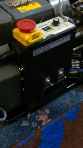
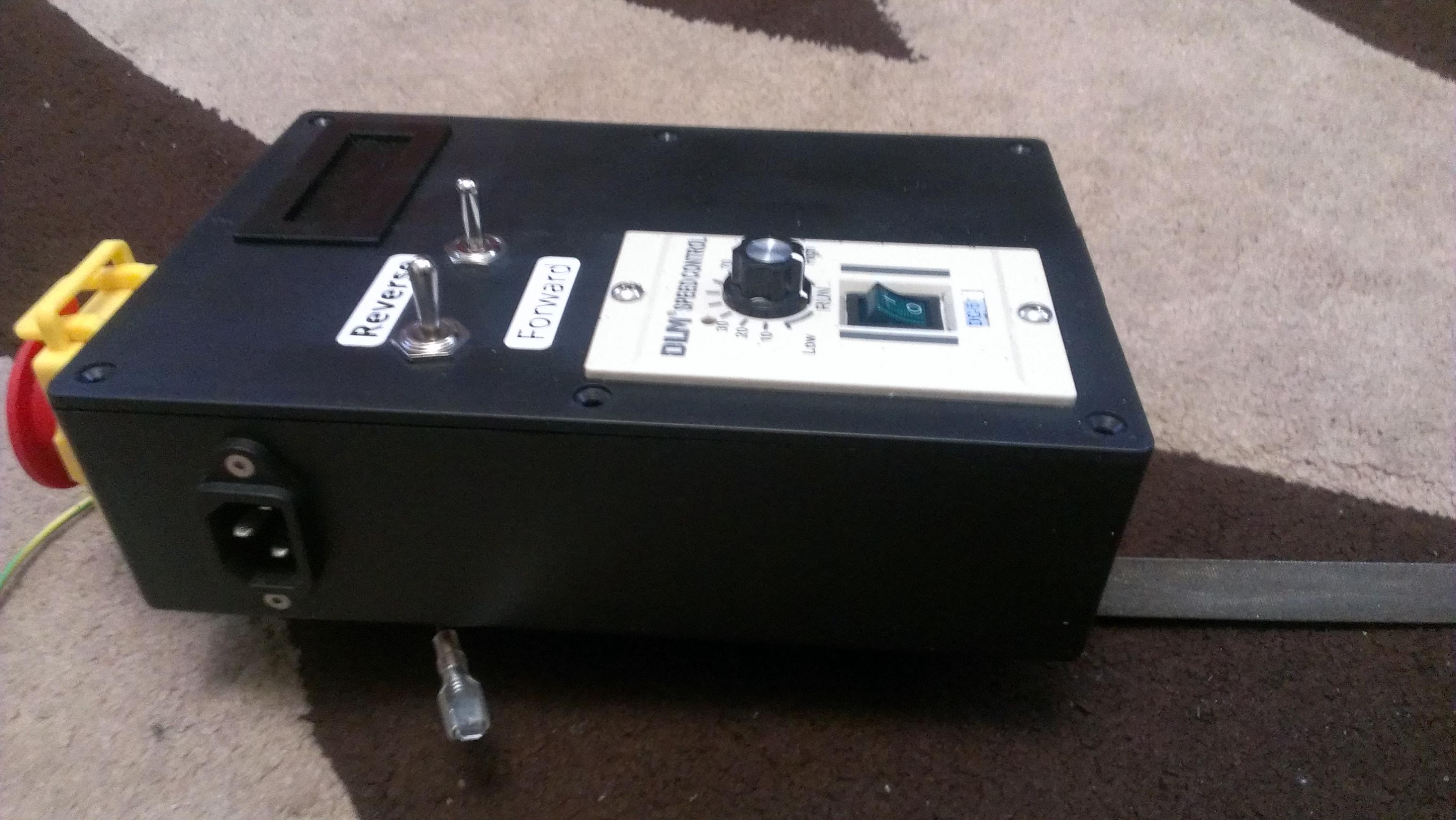
ORIGINAL DESIGN:-
,
Time to redesign! I bought a second set of parts :- control box , Thump switch (emergency lock out ) Toggle switches, Tacho panel, Fans , 240Vac to 12VDC wall wart and chinese speed controller.
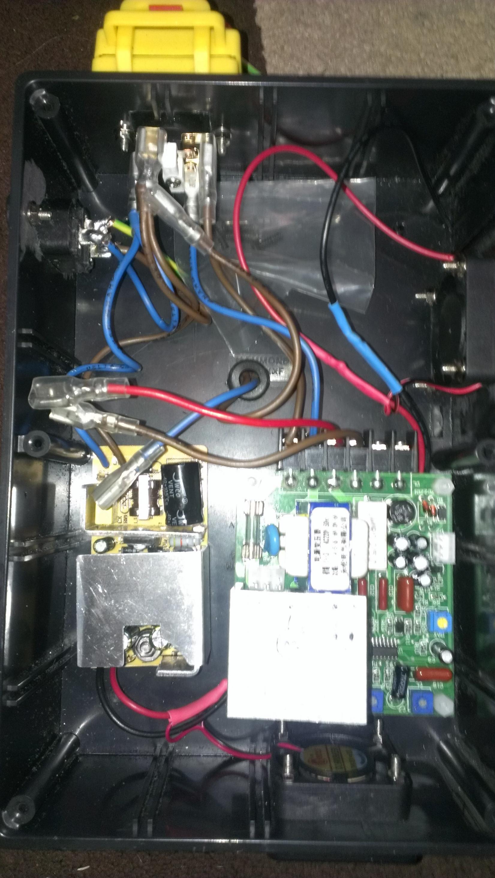
The first thing was to strip the P.C. board from the wall wart (power for the tacho & fans ) & did the same to the new chinese speed controller. the idea being that the control pot & on/off switch with their Bezel/face plate can be mounted remotely from the PCB allowing greater flexibility to the layout within the box.
,
The LH lower cct board is the "wall wart" innards and the RH cct board is the Chinese speed controller
The speed controler board has a huge heat sink on it and since it now sat in a far larger but fully sealed case, I added two 40mm fans one mounted directly under the heat sink (when the box is mounted vertically on the lathe ) in the base of the box sucking cool air in, the second fan is almost on the top of the right hand side blows the warm air out.
Having done all that I am now far happier with the layout. (PHOTO'S to Follow ):-
,
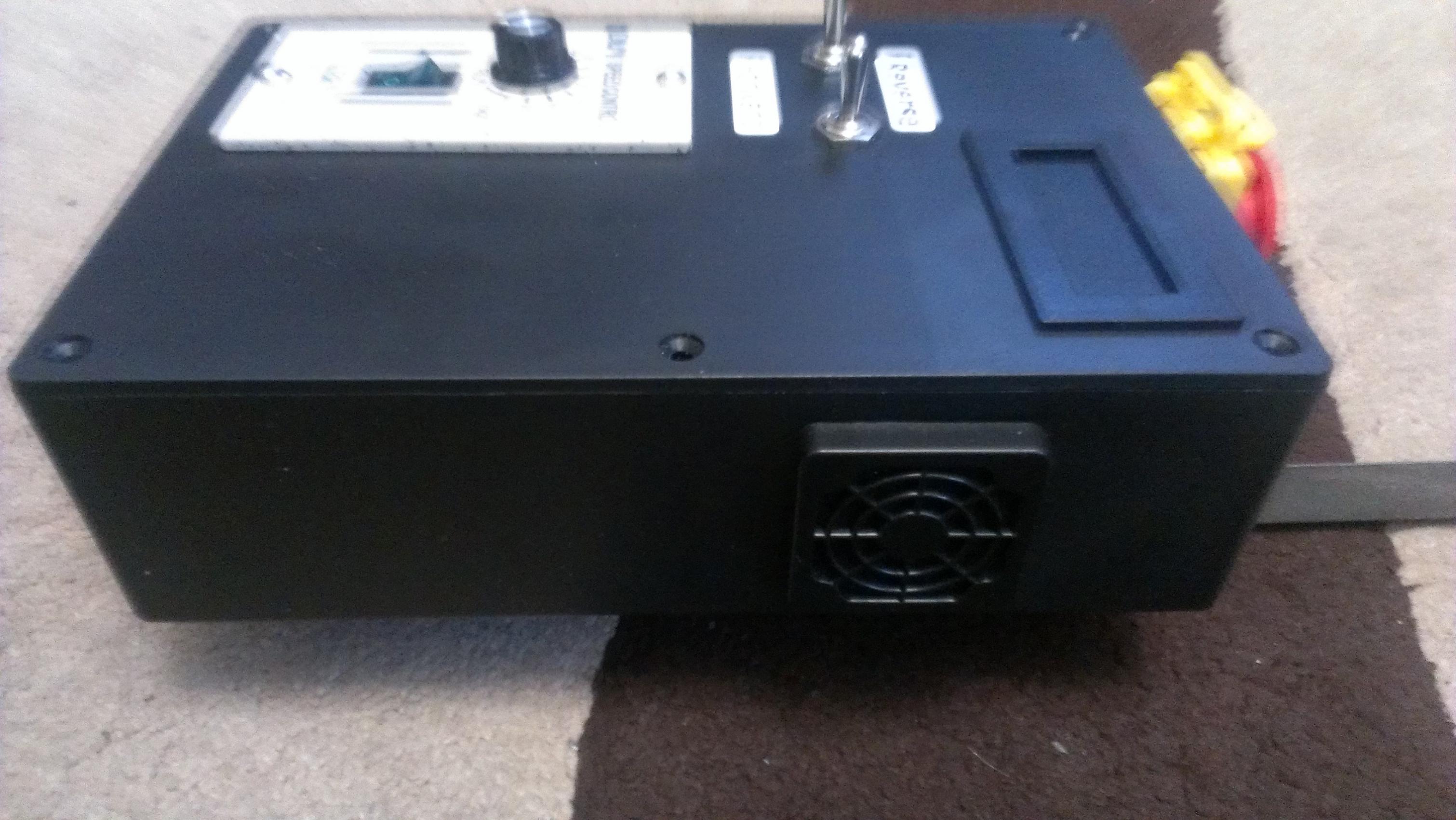
RH side exhaust fan
,
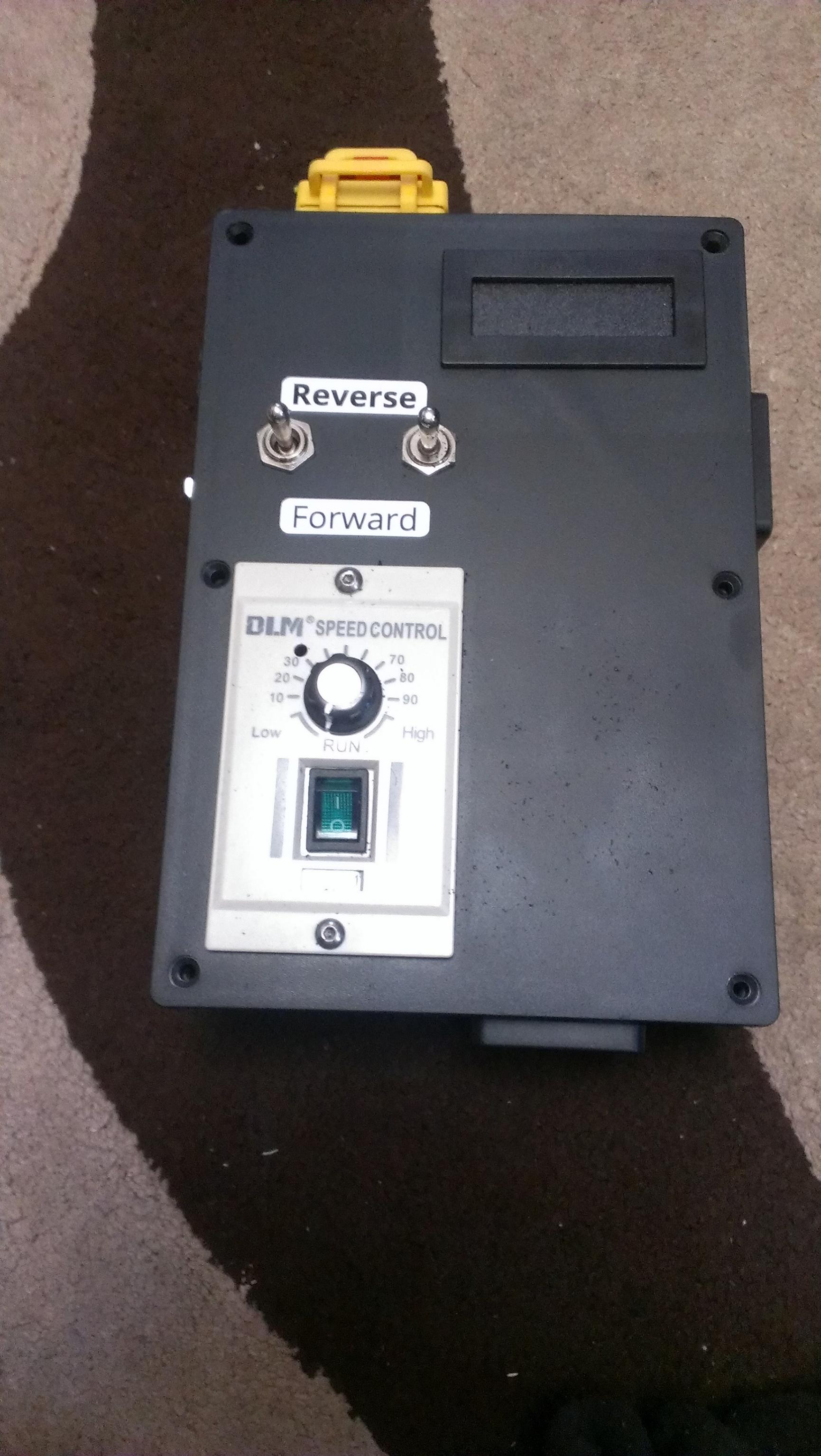
Front facia layout (also shows the lower inlet fan filter in place )
LH side mains input for "kettle lead "
the next major job was to replace the head stock bearings for tapered ones (the original are plain ball bearings ) whilst i was at it I decided on checking the plastic gears inside. NOT IMPRESSED so i ordered the cast steel versions at the same time as I ordered the bearings.
I had better point out at this point I never undertake anything I am not well read up on when it comes to spending money, so i read everything and watched endless videos on converting mini-lathes. and in particular bearing replacement & head stock "stuff".
So all the bits are in and i started work and being super cautious I went to a Pals workshop for the day to do this "just in case ".
Now the plastic spindle gears are all one part with a a 40mm long key & keyway. Now the metal gears come in THREE parts two gears and a spacer which when put together as a stack on a face plate are with 5 thou of the plastic one piece in overall length. So far so good.
However when you assemble said three pieces on the spindle the key is not long enough to drive the last gear ! it is TOO SHORT by 10mm at least.
After much use of quite a few Anglo Saxon invectives my pal and i decided to lengthen the original keyway by 12mm however neither of us had any 5mm key material available . So I cut the original key in half (reasoning that since the spacer between the two gears takes no force it needs no direct drive power only to stay in place and not chafe against the two gears by having it "idle".
The two keys are now kept apart by a 4mm silver steel rod so they stay put & drive the spindle thro the gears as intended.
An exciting day! What i cannot understand is that NONE of my reading has highlighted this MAJOR design flaw in the 3 piece gear conversion kit.
OR is it that with my luck my spindle was a friday afternoon spindle that did not have the proper length cut keyway in the first place ?
Thoughts......................................
QUESTION:- I have inherited a 3 PHASE 240v DC MOTOR need a control circuit for it ? loads of guff on 3 PHASE AC motors none on DC pointers PLEASE ........................TIA


 Reply With Quote

Bookmarks