Free 186 More Best Homemade Tools eBook:  
Get 2,000+ tool plans, full site access, and more.

User Tag List

Page 2 of 2 FirstFirst 1 2
Results 11 to 17 of 17

Thread: 3Hp hydraulic power unit

  1. #11
    Supporting Member MeJasonT's Avatar
    Join Date
    Jun 2016
    Location
    Lake District in UK
    Posts
    432
    Thanks
    455
    Thanked 279 Times in 162 Posts

    MeJasonT's Tools
    Still researching
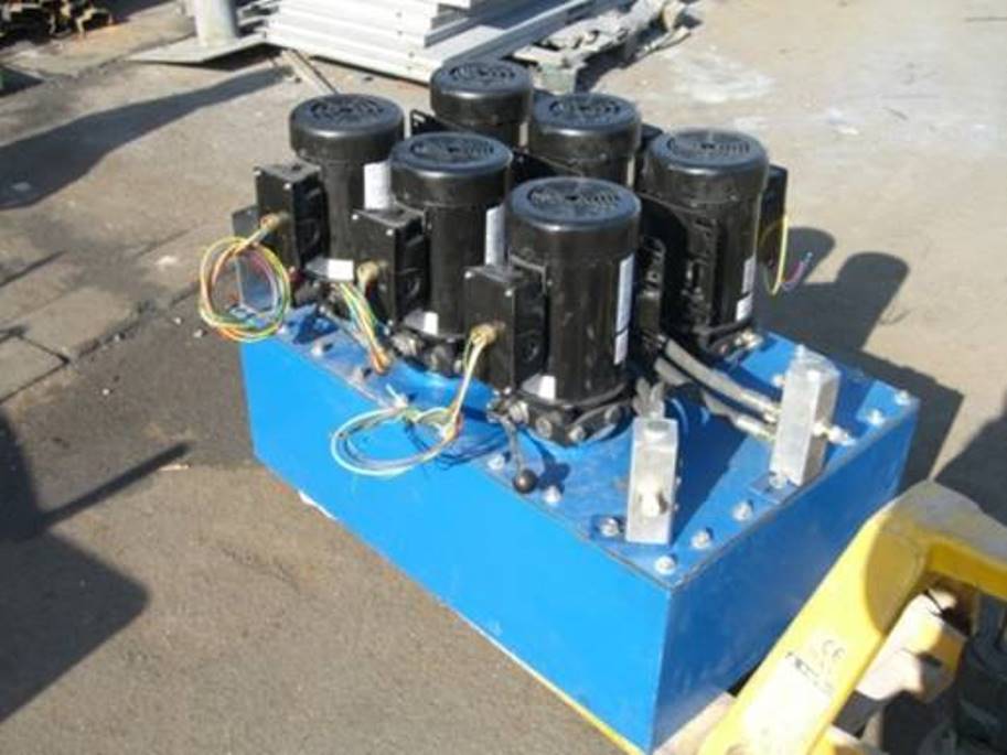
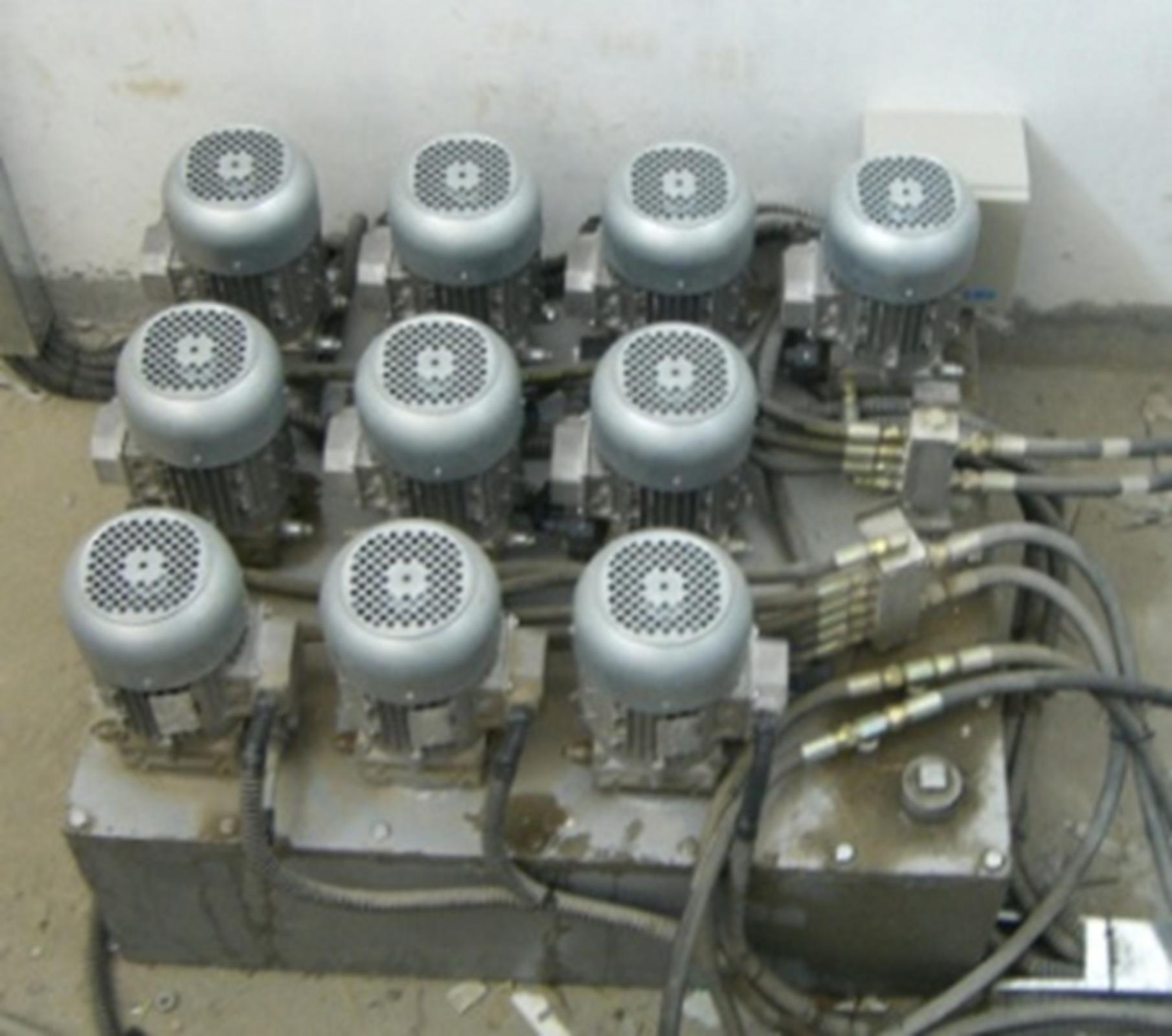
    pressure washer as hydraulic pump
    I'm currently pondering two conclusions
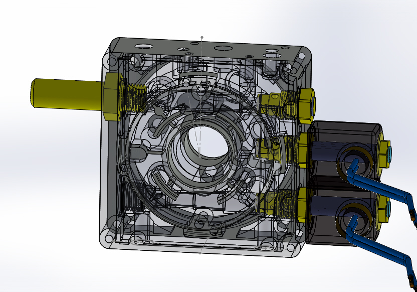
    The seals thing is a myth. The o rings and seals are more than likely all viton (rockwell 80 hardness)which will be identical to most hydraulics and cylinders i,ve ever come across - its not as if they are irreplaceable.
    However as you/Frank quite rightly pointed out is probably the wrong sort of pump, based on the information in the above link the pressure is dictated by the orifice and not the pumps ability to provide the volume and pressure. Oh well Water jet cutter it is then. just need a pressure amplifier and ceramic/ruby nozzles now.

    https://hackaday.com/2017/05/31/a-wa...essure-washer/

    186 More Best Homemade Tools eBook
    Citizen of the "New democratic" Republic of Britain, liberated from the EuroNation

  2. #12
    Supporting Member Frank S's Avatar
    Join Date
    Aug 2015
    Location
    Peacock TX
    Posts
    11,212
    Thanks
    1,983
    Thanked 8,787 Times in 4,206 Posts

    Frank S's Tools
    As I mentioned I doubted that seals would be part of the problem in using a PW pump as a hydraulic pump. because as you pointed out Viton seals are used in applications all across the spectrum. any rubber seals would be a durometer of 80 or better Ceramic seals have been used in some Sunstrand piston pumps for years Rexroth Vickers Parker Charlyn all have and do use ceramics in various models of their pumps and motors.
    the Cavitation issue is easily solved by having the reservoir above the pump with an oversized feed line. or a simple low pressure rotary vane, centrifugal or gear pump as a charge pump to feed the piston pump. even a salvaged power steering pump from automotive would work well for this.
    Building a water jet system using a PW pump could most certainly be done with pressure intensifiers I would think the productive output would be severely limited due to the large volume loss for increasing pressures from a modest 2-4000 PSi up to the 20,000 to 100,000 PSi normally found in water jet systems but again doable by paralleling 2 or more Pw pumps in a system using back pressure checks to prevent reverse flow between the pumps.
    here is a 6 pump power unit I made out of individual 3 Hp pumps
    3Hp hydraulic power unit-6-pump-power-unit-1.jpg
    I've used these pumps to make power units ranging from a singular stand alone unit all the way to having as many as 10 pump motor assemblies mounted on a single tank. The advantages of doing this was rather than having a single 30 HP motor pulling a 20 gallon pump when only 2 gallons were required or wanted for flow instead of having a variable displacement pump with an out flow of 2 GPM being powered by a 30 Hp motor when only 3 Hp was required for the amount of fluid being moved the savings in electricity usage was 10 fold As flow requirements increased or decreased the motors would automatically come on line or drop off line Also greatly reducing the inrush current load. another advantage was if a single pump or motor were to ever go bad the whole system was not shut down it could still be operated at a diminished capacity if need be. Where as if a single large pump motor went down everything was shut down until repairs could be made.

    2000 Tool Plans
    Never try to tell me it can't be done
    When I have to paint I use KBS products

  3. The Following 2 Users Say Thank You to Frank S For This Useful Post:

    MeJasonT (Aug 23, 2019), metric_taper (Aug 22, 2019)

  4. #13
    Supporting Member Frank S's Avatar
    Join Date
    Aug 2015
    Location
    Peacock TX
    Posts
    11,212
    Thanks
    1,983
    Thanked 8,787 Times in 4,206 Posts

    Frank S's Tools
    And here is 1 of my 10 pump power units
    This one was used to power 2 40 ton freight elevators from 1 to all 10 pumps could be used to raise either platform
    3Hp hydraulic power unit-10-pump-power-unit.jpg
    Never try to tell me it can't be done
    When I have to paint I use KBS products

  5. The Following User Says Thank You to Frank S For This Useful Post:

    MeJasonT (Aug 23, 2019)

  6. #14
    Supporting Member metric_taper's Avatar
    Join Date
    Mar 2017
    Location
    Marion, Iowa
    Posts
    585
    Thanks
    228
    Thanked 257 Times in 153 Posts

    metric_taper's Tools
    Quote Originally Posted by Frank S View Post
    And here is 1 of my 10 pump power units
    This one was used to power 2 40 ton freight elevators from 1 to all 10 pumps could be used to raise either platform
    Click image for larger version. 

Name:	10 pump power unit.jpg 
Views:	126 
Size:	167.4 KB 
ID:	30820
    I see some sort of manifold that must collect the outputs from each pump. I assume this has a check valve for each pump, so you can't back drive a pump that is off.
    What sequence method controls the various pumps? That has to be where the major cleverness is, assuming you designed that as well.
    I can't think of this being pressure, that just seems to have too many switches to adjust for cutin and cutout. A demand sensor of some type?
    I hope this is not some intellectual property that prevents you from sharing the operation.

  7. The Following User Says Thank You to metric_taper For This Useful Post:

    MeJasonT (Aug 26, 2019)

  8. #15
    Supporting Member Frank S's Avatar
    Join Date
    Aug 2015
    Location
    Peacock TX
    Posts
    11,212
    Thanks
    1,983
    Thanked 8,787 Times in 4,206 Posts

    Frank S's Tools
    Quote Originally Posted by metric_taper View Post
    I see some sort of manifold that must collect the outputs from each pump. I assume this has a check valve for each pump, so you can't back drive a pump that is off.
    What sequence method controls the various pumps? That has to be where the major cleverness is, assuming you designed that as well.
    I can't think of this being pressure, that just seems to have too many switches to adjust for cutin and cutout. A demand sensor of some type?
    I hope this is not some intellectual property that prevents you from sharing the operation.
    Well part of it might be considered intellectual property I can't show any actual pictures of the controller that I designed simply because I don't have access to them in a failed hard drive LOL I will tell you a little about it though but first
    your inquiry of the check valves and the distribution manifolds
    in each pump assembly I designed additional ports and cavity passages into an existing factory mono block motor/ pump adapter block then traveled to the manufacture in Italy a company by the name of Hydronit through a collaboration between their engineers and me we came up with a block that not only suited my needs but extended the usefulness of their products to be used in a wider field of applications. Their blocks already had cavities for check valves relief valves and 2 way solenoid operated poppet valves what my proposal was to make the cavities in the blocks to accept 4 way poppet valves by doing this it opened up a range which would accept flow restrictor valves duel power outputs differential pressure outputs and many other things such as building a multiple pump arrangement.
    here is a jpeg of the block It would be most difficult for anyone to duplicate this block from this drawing alone since there are many passages and ports in the block
    And yes their block is patented not sure about the changes that I made to them but I should hope they did
    3Hp hydraulic power unit-hydronit-valve-body1.jpg
    Now for the controller basically since my freight elevators were mainly used for 2 to 4 stops the controller to accelerate and slow the platform amounted to a few limit switches and a friction wheel sequential rotary switch. a series of relays and solenoid valves already in the pumps
    the operator or person at the door would push the call button a pump would start the platform began to move then that pump would go to full volume the 2nd pump would start with the fluid being briefly diverted a valve would close this would show a brief acceleration the 2nd solenoid would allow that one to go to full volume and the process would be repeated until as many pumps that were dedicated to the unit would all be on line as the platform reached the level going up the pumps would sequentially fall off until full stop. for going down it was a little different as the same valves in the pumps were used but the flow returned through the flow restrictor valves the pumps were not running. there were velocity check valves which would lock down the whole thing in the event of a broken hose. these were located in those manifolds you mentioned this was done to allow the platform to still be raised or lowered even if you removed a hose leading from 1 or more of the pumps, with a main velocity check made into the cylinders in the event of the hose to the cylinder was to burst or was cut intentionally. This did happen once by a guy who thought he could destroy the left by hacking a hose off with an ax. all he managed to do was get oil all over himself and a nice prison stay. `
    Never try to tell me it can't be done
    When I have to paint I use KBS products

  9. The Following User Says Thank You to Frank S For This Useful Post:

    MeJasonT (Aug 26, 2019)

  10. #16
    Supporting Member Radioman's Avatar
    Join Date
    Jun 2018
    Location
    Massachusetts
    Posts
    209
    Thanks
    11
    Thanked 87 Times in 53 Posts

    Radioman's Tools
    Frank, if I may ask—-What is your level of education?

    You sound like a very smart person. Engineer?

  11. #17
    Supporting Member Frank S's Avatar
    Join Date
    Aug 2015
    Location
    Peacock TX
    Posts
    11,212
    Thanks
    1,983
    Thanked 8,787 Times in 4,206 Posts

    Frank S's Tools
    Quote Originally Posted by Radioman View Post
    Frank, if I may ask—-What is your level of education?

    You sound like a very smart person. Engineer?
    We'll just leave it at retired industrial design engineer, and about 75% autodidact who lost more than a significant amount due to oxygen depravation to the brain from an illness back in 2011


    186 More Best Homemade Tools eBook
    Never try to tell me it can't be done
    When I have to paint I use KBS products

  12. The Following User Says Thank You to Frank S For This Useful Post:

    MeJasonT (Aug 26, 2019)

Thread Information

Users Browsing this Thread

There are currently 1 users browsing this thread. (0 members and 1 guests)

Bookmarks

Posting Permissions

  • You may not post new threads
  • You may not post replies
  • You may not post attachments
  • You may not edit your posts
  •